manuals.online logo
Brands
  1. Home
  2. •
  3. Brands
  4. •
  5. tell
  6. •
  7. Door Lock
  8. •
  9. tell CL600 User manual

tell CL600 User manual

1-800-433-4047 | CL102258-04092020Tell Manufacturing | A Division of Spectrum Brands Inc. 1
INSTRUCTIONS AND TEMPLATE FOR
CL600 PK PANIC KIT
MECHANICAL LOCK
READ AND FOLLOW
INSTRUCTIONS CAREFULLY.
Incorrect installation or adjustment
could cause damage or injury.
1. Fit Rubber gasket onto the back of Lock Trim .
2. Screw 3 Lock Trim Posts into back of Lock Trim and tighten.
3. Screw 2 Exit Device Posts to the Cover Plate plate and tighten.
4. Fit Cover Plate over the 3 Lock Trim Posts .
5. Attach the Lock Trim to the door using the 2 Bolts and Washer Plate on top and 1 Bolt and Metal
Flange through the 2-1/8” door prep.
(If no door prep, follow template instruction to drill proper holes)
6. Using the correct Spindle, marked L for left hand or R for right hand, fit the spindle set through
the door and insert it to the spindle hole on the Lock Trim.
7. Hold panic device to the door, aligning holes and spindle. Secure to Lock Trim Thru-bolts.
8. Attach the panic device – sold separately.
Lock Trim
Rubber
Gasket
Cover
Plate
Exit Device
(not supplied)
Spindle
(marked
L or R)
Lock
Trim
Posts
Thru-Bolts
(not supplied
w/lock trim)
Thru-Bolts
Exit Device
Bolts
(supplied)
Exit Device
Posts
Lock Trim
Bolts
Metal
Flange
Washer Plate
CL600 Mechanical Lock Trim
Using the template on page 2, install the CL600 Lock Trim with the Exit Device. Tape
template to the door, mark the holes and drill where needed.
1-800-433-4047 | CL102258-04092020Tell Manufacturing | A Division of Spectrum Brands Inc. 2
TEMPLATE FOR RIM EXIT DEVICE
CL600 PK PANIC KIT
CL600 Mechanical Lock Trim
1. Align template center-line (CL) with the CL of the Exit Device (as illustrated). Tape
template to the door, mark the holes and drill where needed.
Drill 3/8” (10mm)
holes for
thru bolts
attached to lock trim
Drill 3/8” (10mm)
holes for
panic thru bolts
attached to Plate
1-5/8”
(42mm)
1-3/8”
(35mm)
1”
3/8”
C
L
7/8”
(22mm)
5-3/8”
(137mm)
3-3/8”
(86mm)
3-3/8”
(86mm)
If there is no 2-1/8” Door Prep,
drill the following 1” dia. and
3/8” dia. holes.
Use metal flange to cover
2-1/8” door prep, to
attach bottom of lock trim.
Print PDF at 100%
Actual Size
Template
Actual Size
1” Square
2-1/8”
Door Prep
C
L
C
L
C
L
C
L

Other tell Door Lock manuals

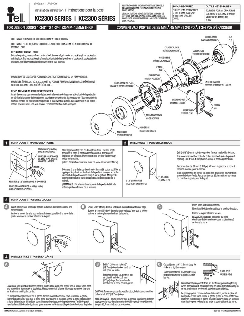
tell KC2300 Series User manual

tell

tell KC2300 Series User manual

tell CL600 Administrator guide

tell

tell CL600 Administrator guide

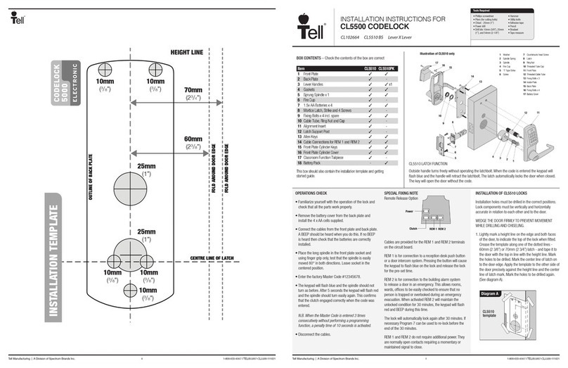
tell CODELOCK CL5500 Series User manual

tell

tell CODELOCK CL5500 Series User manual

tell KC2300 Series User manual

tell

tell KC2300 Series User manual

Popular Door Lock manuals by other brands
LOCKLY GUARD VISION DUO user manual

LOCKLY GUARD

LOCKLY GUARD VISION DUO user manual

Kaba Solitaire 710-II Series installation instructions
Kaba

Kaba Solitaire 710-II Series installation instructions

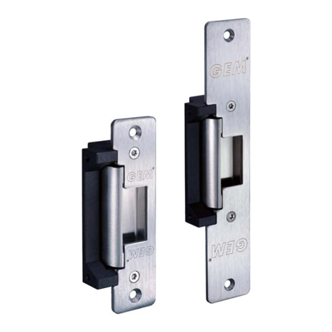
GEM GL-850 Specification sheet

GEM

GEM GL-850 Specification sheet

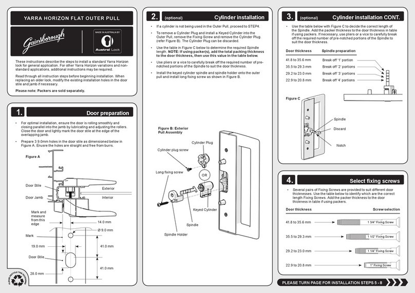
Austral Lock Gainsborough YARRA HORIZON FLAT OUTER PULL installation instructions
Austral Lock

Austral Lock Gainsborough YARRA HORIZON FLAT OUTER PULL installation instructions

hager 3500 Series installation instructions

hager

hager 3500 Series installation instructions

Milocks QKK-02 quick start guide

Milocks

Milocks QKK-02 quick start guide

RemoteLock OpenEdge BG Hardware installation

RemoteLock

RemoteLock OpenEdge BG Hardware installation

Allegion FALCON 24-C installation instructions

Allegion

Allegion FALCON 24-C installation instructions

Siegenia-AUBI KFV EE99 Series Assembly instructions

Siegenia-AUBI

Siegenia-AUBI KFV EE99 Series Assembly instructions

Dorma HZ 43-F Series Mounting instructions

Dorma

Dorma HZ 43-F Series Mounting instructions

Vicenza Designs DHPA8005 Instructions for installation
Vicenza Designs

Vicenza Designs DHPA8005 Instructions for installation

ResortLOCK RL2000 Quick operation guide

ResortLOCK

ResortLOCK RL2000 Quick operation guide

Kaba Peaks Preferred Technical manual

Kaba

Kaba Peaks Preferred Technical manual
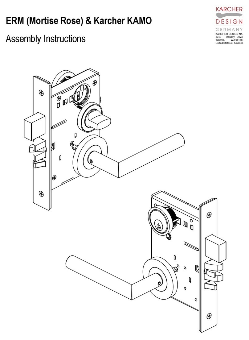
Karcher Design ERM Series Assembly instructions

Karcher Design

Karcher Design ERM Series Assembly instructions

I.H.T 707 Quick setup guide

I.H.T

I.H.T 707 Quick setup guide

Gianni Industries GK320 Series Installation instruction
Gianni Industries

Gianni Industries GK320 Series Installation instruction

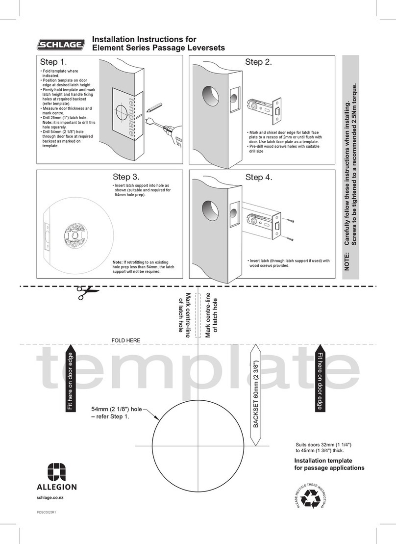
Allegion SCHLAGE Element Series installation instructions
Allegion

Allegion SCHLAGE Element Series installation instructions

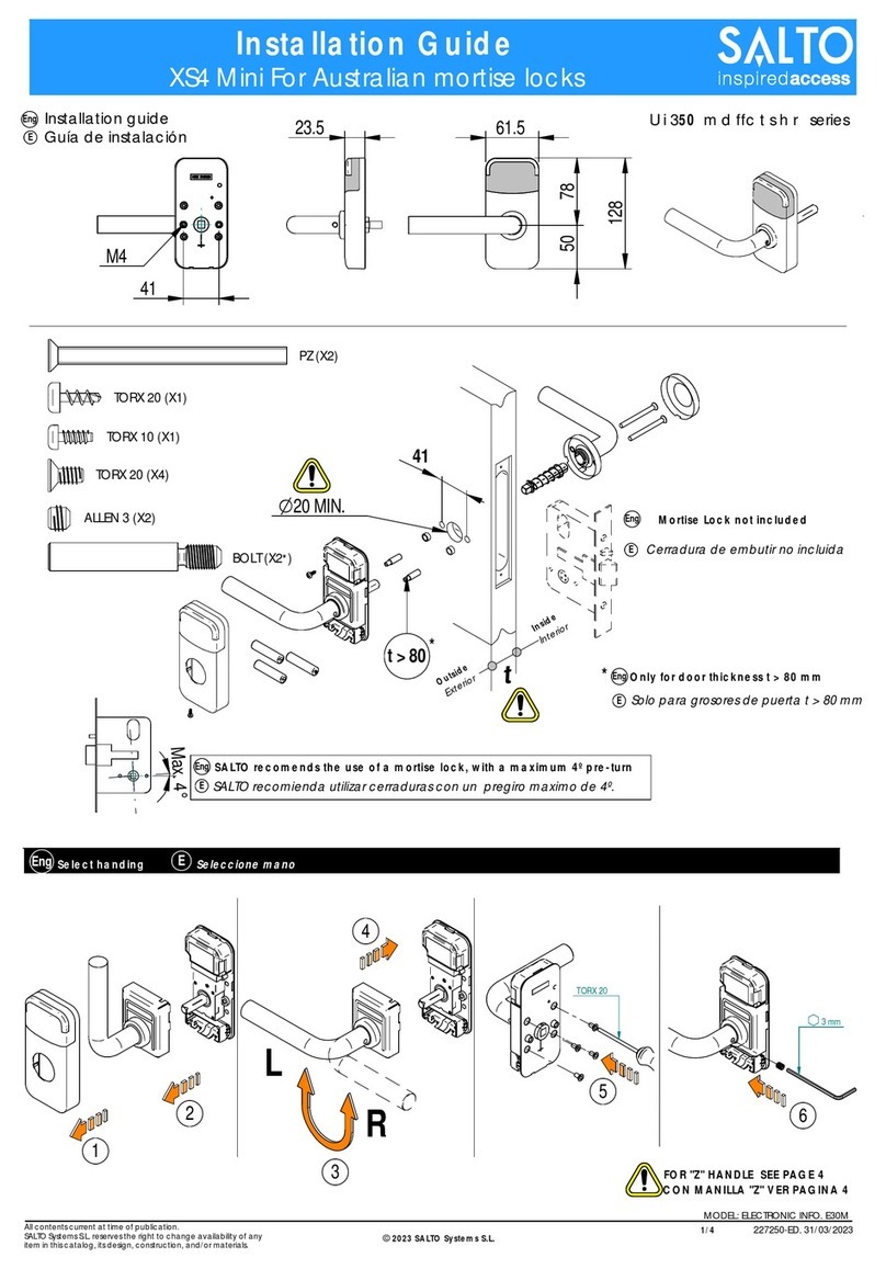
Salto XS4 Mini installation guide

Salto

Salto XS4 Mini installation guide

manuals.online logo
manuals.online logoBrands
  • About & Mission
  • Contact us
  • Privacy Policy
  • Terms and Conditions

Copyright 2025 Manuals.Online. All Rights Reserved.