Southwestern Industries TRAK TMC5 Guide
TRAK®TMC
ProtoTRAK®RMX CNC
Safety, Installation, Maintenance, Service and Parts List
Covers Current Models:
•TRAK TMC5
•TRAK TMC7
•TRAK TMC10
•TRAK TMC12
•TRAK TMC14
Covers Previously Branded Models:
•TRAK VMC5
•TRAK VMC7
•TRAK VMC10
Document: P/N 31551
Version: 082521
2615 Homestead Place
Rancho Dominguez, CA 90220-5610 USA
T | 310.608.4422 | F | 310.764.2668
Service Department: 800.367.3165

Copyright ©2021, Southwestern Industries, Inc. All rights are reserved. No part of this publication may
be reproduced, stored in a retrieval system, or transmitted, in any form or by any means, mechanical,
photocopying, recording or otherwise, without the prior written permission of Southwestern Industries,
Inc.
While every effort has been made to include all the information required for the purposes of this guide,
Southwestern Industries, Inc. assumes no responsibility for inaccuracies or omission and accepts no
liability for damages resulting from the use of the information contained in this guide.
All brand names and products are trademarks or registered trademarks of their respective holders.
TRAK Machine Tools
Southwestern Industries, Inc.
2615 Homestead Place
Rancho Dominguez, CA 90220-5610
Phone 310.608.4422 ▪ Fax 310.764.2668
Service Department
Phone 800.367.3165 ▪Fax 310.886.8029
Web: www.trakmt.com

i
TRAK Machine Tools
Southwestern Industries, Inc.
TRAK TMC with ProtoTRAK RMX CNC Safety, Installation, Maintenance, Service & Parts List
Table of Contents
1.0 Safety ....................................................................................................... 1
1.1 Safety Publications ...............................................................................................................1
1.2 Danger, Warning, Caution, Note Labels & Notices as Used in This Manual ...............................1
1.3 Tool Room Op and Production Op .........................................................................................7
1.4 Safety Precautions................................................................................................................8
2.0 Installation of TRAK TMC Series Machining Centers............................. 10
2.1 Installation Requirements ...................................................................................................10
2.2 Overall Dimensions.............................................................................................................11
2.3 Cleaning the TMC ...............................................................................................................16
2.4 Lifting and/or Placing the TMC ............................................................................................17
2.4.1 Lifting the TMC Using a Crane .........................................................................................18
2.5 Uncrating the TMC .............................................................................................................19
2.5.1 Releasing the Head Support Bracket ................................................................................22
2.6 Leveling Procedure .............................................................................................................22
2.6.1 Leveling Pad Specifications..............................................................................................22
2.6.2 Leveling Procedure .........................................................................................................24
2.6.3 Adjusting Level for Tram .................................................................................................25
2.7 Shortages: Inventory Checklist............................................................................................26
2.8 Electrical Connection ..........................................................................................................27
2.8.1 Main Power to the Machine Connections ..........................................................................28
2.8.2 Transformer Option ........................................................................................................28
2.9 Air Connection ...................................................................................................................29
2.9.1 Air Regulators and Solenoids ...........................................................................................29
2.10 Placing the Coolant System .................................................................................................31
2.11 Installation Checklist...........................................................................................................32
2.12 Lubrication.........................................................................................................................37
2.12.1 Way Lubrication ..........................................................................................................37
2.12.2 Other TMC Lubrication Points.......................................................................................38
2.13 Machine Specifications........................................................................................................39
2.13.1 Maximum Spindle Torque & HP....................................................................................44
2.14 ProtoTRAK RMX Euclid Block Procedure ...............................................................................46
3.0 Troubleshooting by Symptom................................................................ 48
3.1 Problems Relating to Machining Results ...............................................................................48
3.1.1 Poor Finish .....................................................................................................................48

ii
TRAK Machine Tools
Southwestern Industries, Inc.
TRAK TMC with ProtoTRAK RMX CNC Safety, Installation, Maintenance, Service & Parts List
3.1.2 Circles Out of Round .......................................................................................................49
3.1.3 Parts Have Incorrect Dimensions .....................................................................................49
3.2 Motion Related Problems ....................................................................................................50
3.2.1 Run Away Axis................................................................................................................50
3.2.2 Axis Will Not Jog with Electronic Handwheel .....................................................................50
3.2.3 Searching Axis ................................................................................................................51
3.2.4 Homing Error –Axis, Tool Changer ..................................................................................51
3.3 Computer Related Issues ....................................................................................................52
3.3.1 USB Not Working on Pendant Enclosure ...........................................................................52
3.3.2 Programming Panel Does Not Power On...........................................................................53
3.3.3 Blank Display..................................................................................................................54
3.3.4 White Display .................................................................................................................55
3.3.5 System Will Not Boot ......................................................................................................55
3.3.6 E-Stop Error ...................................................................................................................56
3.3.7 Overlay Keys Not Responding..........................................................................................57
4.0 Automatic Tool Changer Operation and Service Codes......................... 59
4.1 Tool Changer Operation......................................................................................................59
4.2 Spindle Orientation.............................................................................................................59
4.3 Tool Change Height............................................................................................................59
4.4 Tool Changer Sensors.........................................................................................................60
4.4.1 ATC Home Position Sensor ..............................................................................................60
4.4.2 ATC Counter Sensor........................................................................................................61
4.4.3 ATC Tool Detect Sensor ..................................................................................................61
4.4.4 ATC “In” ........................................................................................................................63
4.4.5 ATC “Out” ......................................................................................................................63
4.4.6 Tool “Unclamp” ..............................................................................................................63
4.4.7 Tool “Clamp” ..................................................................................................................63
4.5 ATC Flow Control Valves .....................................................................................................63
4.6 Error Messages Relating to the ATC.....................................................................................64
4.7 Diagnostics Table ...............................................................................................................65
4.8 Service Codes ....................................................................................................................66
4.8.1 Section A - Software Code Details....................................................................................68
4.8.2 Section B - Machine Set-Up Code Details..........................................................................69
4.8.3 Section C - Diagnostic Code Details..................................................................................71
4.8.4 Section D - Operator Defaults/Options Codes Details ........................................................72

iii
TRAK Machine Tools
Southwestern Industries, Inc.
TRAK TMC with ProtoTRAK RMX CNC Safety, Installation, Maintenance, Service & Parts List
4.9 Critical Service Codes that Must Be Performed .....................................................................73
5.0 Procedure for Replacements & Maintenance ........................................ 74
5.1 Replacements ....................................................................................................................74
5.1.1 Servo Drive Replacement ................................................................................................74
5.1.2 Programming Panel, Run Panel and Computer Module Replacement ..................................74
5.1.3 Updating the Pendant and CM Software ...........................................................................78
5.1.4 Adding Solid State Drive (SSD) Memory Option ................................................................78
5.1.5 Cable Routing on Machine ...............................................................................................81
5.1.6 Electronic Handwheel Option ...........................................................................................82
5.1.7 Electronic Handwheel and Sensor Replacement ................................................................84
5.1.8 Auger Motor, Coolant and Coolant Wash Down Pump Replacements..................................86
5.1.9 Servomotor Replacement ................................................................................................88
5.2 Maintenance ......................................................................................................................93
5.2.1 How to Clean the Touchscreen ........................................................................................93
5.2.2 Periodic Maintenance ......................................................................................................93
5.3 Laser Calibration ................................................................................................................93
5.3.1 Accuracy ........................................................................................................................93
5.3.2 Code 123: Calibration .....................................................................................................94
5.3.3 Calibration Table ............................................................................................................95
6.0 4th Axis Option ....................................................................................... 96
6.1 4th Axis Specifications .........................................................................................................96
6.2 Mounting the 4th Axis..........................................................................................................97
6.3 Installation Checklist of the 4th Axis .....................................................................................99
6.4 Service Codes: 4th Axis ..................................................................................................... 100
6.4.1 Code 318: Turn on 4th Axis Option ................................................................................. 100
6.4.2 Code 128: Input Backlash Constant ............................................................................... 100
6.4.3 Code 502: Set Base Tool Offset ..................................................................................... 101
6.4.4 Code 505: A Axis Motor Index .......................................................................................101
6.4.5 Code 506: Set 4th Axis Offsets ....................................................................................... 101
6.5 Troubleshooting by Symptom............................................................................................ 102
6.6 Servomotor Replacement Procedures ................................................................................ 103
6.6.1 Servomotor Replacement Service Codes......................................................................... 104
6.6.2 Chuck and Adapter Plate Removal and Replacement ....................................................... 104
7.0 Coolant Through Spindle (CTS) Option ............................................... 105
7.1 CTS Sensors and Filter Location ........................................................................................ 106

iv
TRAK Machine Tools
Southwestern Industries, Inc.
TRAK TMC with ProtoTRAK RMX CNC Safety, Installation, Maintenance, Service & Parts List
7.2 CTS Filter Clog Sensor Operation....................................................................................... 106
7.3 CTS Filter Element Replacement........................................................................................ 107
7.4 CTS Filter Clog Sensor Replacement ..................................................................................107
7.5 CTS Coolant Pressure Sensor ............................................................................................ 108
7.6 CTS Coolant Pressure Sensor Replacement and Calibration .................................................108
7.7 CTS Remove and Replace Pump........................................................................................109
8.0 12K Spindle Option .............................................................................. 110
8.1 12K Spindle Operation ...................................................................................................... 110
8.2 Added Spindle Oil Circulation With 12K Option ...................................................................111
8.3 12K Spindle Maximum Spindle Torque & HP.......................................................................113
8.4 12K Maintenance and Adding Oil ....................................................................................... 114
8.4.1 Oil Type and System Maintenance Intervals ...................................................................114
8.5 Spindle Warm Up Procedure ............................................................................................. 115
8.6 12K Warning Message ...................................................................................................... 115
8.7 Installation Checklist of 12K with CTS ................................................................................ 116
9.0 Introduction to Self-Service ................................................................ 121
9.1 When You Have a Service Problem .................................................................................... 121
9.1.1 Communication with the SWI Customer Service Group.................................................... 121
9.2 Replacements .................................................................................................................. 121
9.2.1 Exchange Program........................................................................................................121
9.2.2 Return Material Authorization (RMA) Number ................................................................. 122
10.0 Appendix –Drawings........................................................................ 123
10.1 Drawing 31530 –4th Axis Assembly ................................................................................... 123
10.2 Drawing 31538 –4th Axis Option ....................................................................................... 126
TRAK Warranty Policy................................................................................... 131

1
TRAK Machine Tools
Southwestern Industries, Inc.
TRAK TMC Mills with ProtoTRAK RMX CNC Safety, Installation, Maintenance, Service & Parts List
1.0 Safety
The safe operation of the TRAK TMC depends on its proper use and the precautions taken by each
operator.
•Read and study this manual and the ProtoTRAK TMC/VMC2 Programming, Operating, and
Care Manual. Be certain every operator understands the operation and safety requirements of
this machine before its use.
•Never run the machine with enclosure doors open when in production ops.
•Always wear safety glasses and safety shoes.
•Always stop the spindle and check to ensure the CNC control is in the stop mode before
changing or adjusting the tool or workpiece.
•Never wear gloves, rings, watches, long sleeves, neckties, jewelry, or other loose items when
operating or around the machine.
•Use adequate point of operation safeguarding. It is the responsibility of the employer to
provide and ensure point of operation safeguarding per OSHA 1910.212 - Milling Machine.
1.1 Safety Publications
Refer to and study the following publications for assistance in enhancing the safe use of this machine.
Safety Requirements for Machining Centers and Automatic, Numerically Controlled Milling,
Drilling and Boring Machines (ANSI B11.23-2002) (R2007). Available from The American National
Standards Institute, 1819 L Street N.W., Washington D.C. 20036
Concepts and Techniques of Machine Safeguarding (OSHA Publication Number 3067). Available
from The Publication Office - O.S.H.A., U.S. Department of Labor, 200 Constitution Avenue, NW,
Washington, DC 0210.
1.2 Danger, Warning, Caution, Note Labels & Notices as Used in This
Manual
DANGER - Immediate hazards that will result in severe personal injury or death. Danger labels on the
machine are red in color.
WARNING - Hazards or unsafe practices which
could
result in severe personal injury and/or damage to
the equipment. Warning labels on the machine are orange in color.
CAUTION - Hazards or unsafe practices, which
could
result in minor personal injury or
equipment/product damage. Caution labels on the machine are yellow in color.
NOTE - Call attention to specific issues requiring special attention or understanding.

2
TRAK Machine Tools
Southwestern Industries, Inc.
TRAK TMC Mills with ProtoTRAK RMX CNC Safety, Installation, Maintenance, Service & Parts List
Safety & Information Labels Used on The TRAK Milling Machines
It is forbidden by OSHA regulations and by law to deface, destroy or remove
any of these labels

3
TRAK Machine Tools
Southwestern Industries, Inc.
TRAK TMC Mills with ProtoTRAK RMX CNC Safety, Installation, Maintenance, Service & Parts List
Safety & Information Labels Used on The TRAK Milling Machines

4
TRAK Machine Tools
Southwestern Industries, Inc.
TRAK TMC Mills with ProtoTRAK RMX CNC Safety, Installation, Maintenance, Service & Parts List
Safety & Information Labels Used on The TRAK Milling Machines

5
TRAK Machine Tools
Southwestern Industries, Inc.
TRAK TMC Mills with ProtoTRAK RMX CNC Safety, Installation, Maintenance, Service & Parts List
Safety & Information Labels Used on The TRAK Milling Machines

6
TRAK Machine Tools
Southwestern Industries, Inc.
TRAK TMC Mills with ProtoTRAK RMX CNC Safety, Installation, Maintenance, Service & Parts List
Safety & Information Labels Used on The TRAK Milling Machines
It is forbidden by OSHA regulations and by law to deface, destroy or remove any of these labels
7
TRAK Machine Tools
Southwestern Industries, Inc.
TRAK TMC Mills with ProtoTRAK RMX CNC Safety, Installation, Maintenance, Service & Parts List
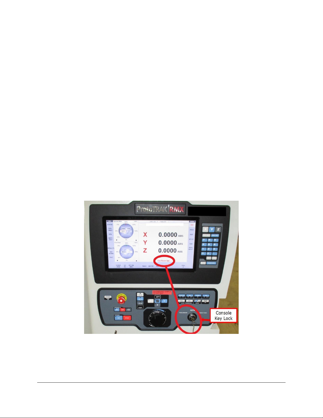
1.3 Tool Room Op and Production Op
TRAK’s TMC’s are designed to be switchable between tool room operation and production operation.
Each operation changes several parameters and methods of use to optimize the machine for each
operation.
Specifically:
Production Operation
•1,000 ipm rapid
•8,000 maximum rpm
•Interlocked door
•ATC (Automatic Tool Changer) operation
•Auto spindle start after tool change
•Full 3 - Axis operation
Tool Room Operation
•400 ipm rapid
•5,000 maximum rpm
•Programs run with door open or closed
•No ATC operation
•Manual Spindle by operator
•Allows manual, 2 –axis and 3 –axis operation
Figure 1.3 shows the TMC Console Programming Panel and Run Panel. Also shown are the key lock
switch to select Tool Room or Production Operation and a display of the current Operation selected.
Figure 1.3 - TMC Programming Panel and Run Panel

8
TRAK Machine Tools
Southwestern Industries, Inc.
TRAK TMC Mills with ProtoTRAK RMX CNC Safety, Installation, Maintenance, Service & Parts List
1.4 Safety Precautions
1. Do not operate this machine before the TRAK TMC Installation, Maintenance, Service and Parts
List Manual, and ProtoTRAK TMC Programming, Operating & Care Manual have been studied and
understood.
2. Do not run this machine without knowing the function of every control key, button, knob, or
handle. Ask your supervisor or a qualified instructor for help when needed.
3. Protect your eyes. Wear approved safety glasses (with side shields) at all times.
4. Don't get caught in moving parts. Before operating this machine remove all jewelry including
watches and rings, neckties, and any loose-fitting clothing.
5. Keep your hair away from moving parts. Wear adequate safety headgear.
6. Protect your feet. Wear safety shoes with oil-resistant, anti-skid soles, and steel toes.
7. Take off gloves before you start the machine. Gloves are easily caught in moving parts.
8. Remove all tools (wrenches, chuck keys, etc.) from the machine before you start. Loose items
can become dangerous flying projectiles.
9. Never operate a milling machine after consuming alcoholic beverages, or taking strong
medication, or while using non-prescription drugs.
10. Protect your hands. Stop the machine spindle and ensure that the CNC control is in the stop
mode:
•Before changing tools
•Before changing parts
•Before you clear away the chips, oil or coolant. Always use a chip scraper or brush
•Before you make an adjustment to the part, fixture, coolant nozzle or take measurements
•Before you open safeguards (protective shields, etc.). Never reach for the part, tool, or fixture
around a safeguard.
11. Protect your eyes and the machine as well. Don't use compressed air to remove the chips or
clean the machine.
12. Disconnect power to the machine before you change belts, pulley, and gears.
13. Keep work areas well lighted. Ask for additional light if needed.
14. Do not lean on the machine while it is running.
15. Prevent slippage. Keep the work area dry and clean. Remove the chips, oil, coolant and
obstacles of any kind around the machine.
16. Avoid getting pinched in places where the table, saddle, tool changer or spindle head create
"pinch points" while in motion.
17. Securely clamp and properly locate the workpiece in the vise, on the table, or in the fixture. Use
stop blocks to prevent objects from flying loose. Use proper holding clamping attachments and
position them clear of the tool path.
18. Use correct cutting parameters (speed, feed, depth, and width of cut) in order to prevent tool
breakage.
19. Use proper cutting tools for the job. Pay attention to the rotation of the spindle: Left hand tool
for counterclockwise rotation of spindle, and right-hand tool for clockwise rotation of spindle.

9
TRAK Machine Tools
Southwestern Industries, Inc.
TRAK TMC Mills with ProtoTRAK RMX CNC Safety, Installation, Maintenance, Service & Parts List
20. After an emergency stop, release the E-stop and press the power reset button for 2 seconds to
turn the servos back on.
21. Prevent damage to the workpiece or the cutting tool. Never start the machine (including the
rotation of the spindle) if the tool is in contact with the part.
22. Check the direction (+ or -) of movement of the table, saddle, and quill when using the jog or
power feed or ram out.
23. Don't use dull or damaged cutting tools. They break easily and become airborne. Inspect the
sharpness of the edges, and the integrity of cutting tools and their holders. Use proper length
tool for the job.
24. Large overhang on cutting tools when not required result in accidents and damaged parts.
25. Inspect the retention knobs for damage or excessive wear before each use.
26. Prevent fires. When machining certain materials (magnesium, etc.) the chips and dust are highly
flammable. Obtain special instruction from you supervisor before machining these materials.
Keep flammable materials and fluids away from the machine and hot, flying chips.
27. Always be certain that you know if the machine is in Production or Tool Room Operation (See
Section 1.3).
28. Always be certain the door is closed during Run Mode when the machine is in Production
Operation.

10
TRAK Machine Tools
Southwestern Industries, Inc.
TRAK TMC Mills with ProtoTRAK RMX CNC Safety, Installation, Maintenance, Service & Parts List
2.0 Installation of TRAK TMC Series Machining Centers
IMPORTANT: Read and understand this entire installation section
before beginning the TMC installation.
2.1 Installation Requirements
Before an Authorized Field Service Technician can perform the machine’s final checkout, detailed
requirements must be met. Please refer to the Site Preparation Guide for the needed set up for your
specific TMC model.

11
TRAK Machine Tools
Southwestern Industries, Inc.
TRAK TMC Mills with ProtoTRAK RMX CNC Safety, Installation, Maintenance, Service & Parts List
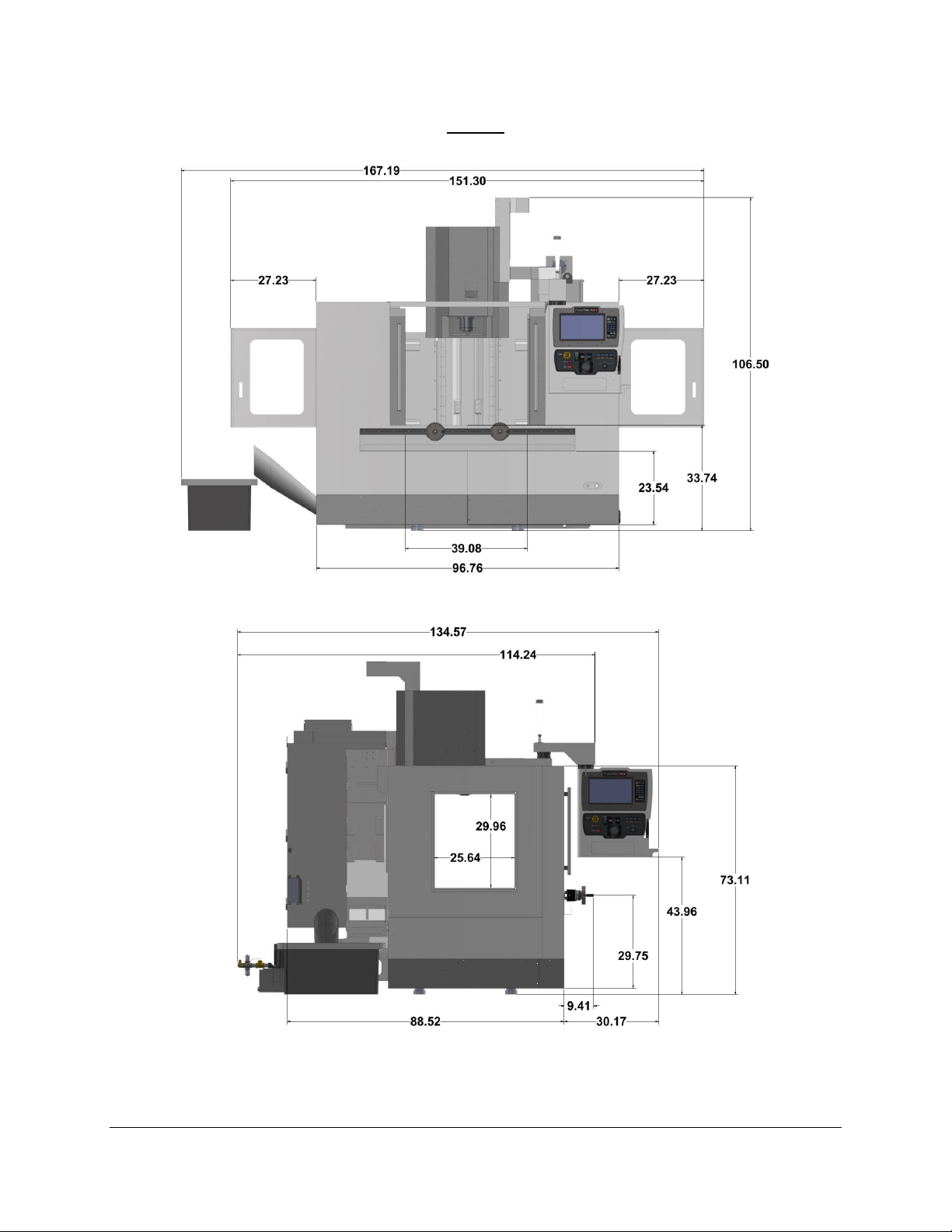
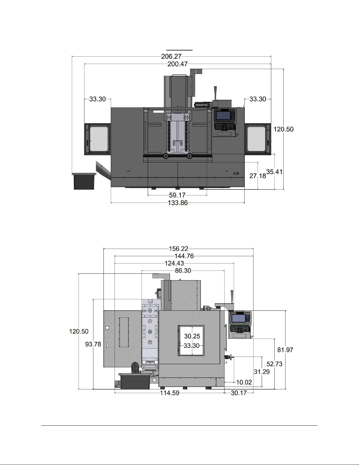
2.2 Overall Dimensions
TMC 5
TMC 5 Front View
TMC 5 Left Side View
12
TRAK Machine Tools
Southwestern Industries, Inc.
TRAK TMC Mills with ProtoTRAK RMX CNC Safety, Installation, Maintenance, Service & Parts List
TMC 7
TMC 7 Front View
TMC 7 Left Side View
13
TRAK Machine Tools
Southwestern Industries, Inc.
TRAK TMC Mills with ProtoTRAK RMX CNC Safety, Installation, Maintenance, Service & Parts List
TMC 10
TMC 10 Front View
TMC 10 Left Side View
14
TRAK Machine Tools
Southwestern Industries, Inc.
TRAK TMC Mills with ProtoTRAK RMX CNC Safety, Installation, Maintenance, Service & Parts List
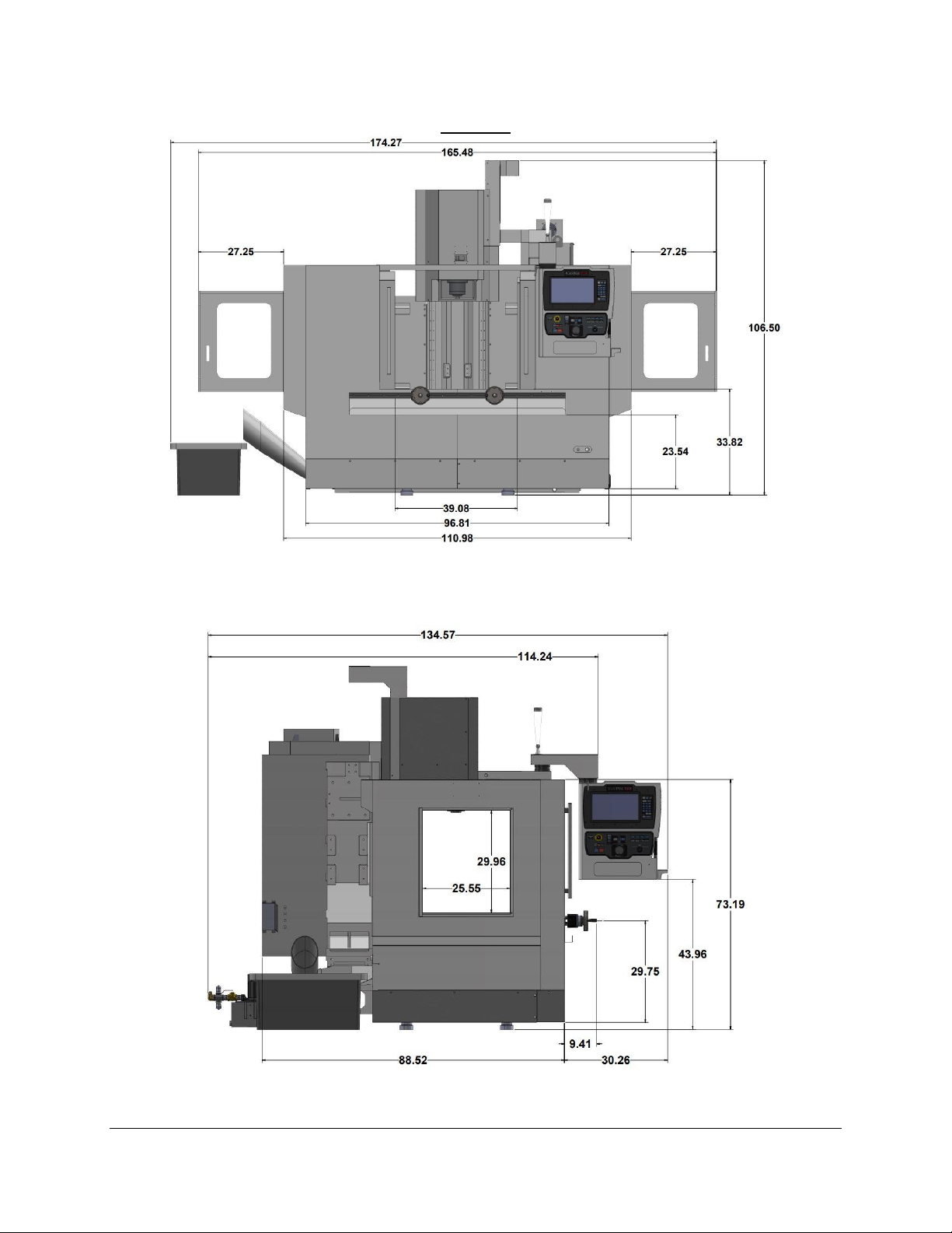
TMC 12
TMC 12 Front View
TMC 12 Left Side View
This manual suits for next models
8
Table of contents
Other Southwestern Industries Industrial Equipment manuals


