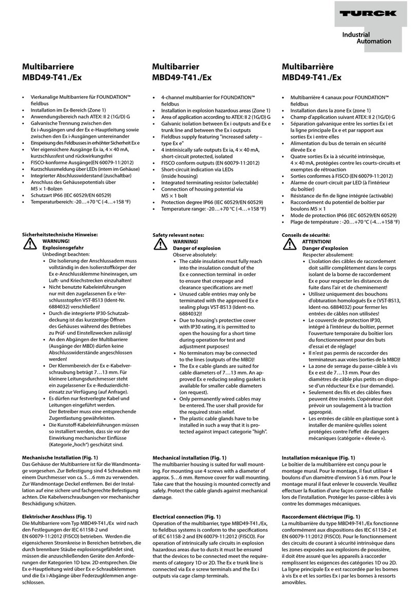
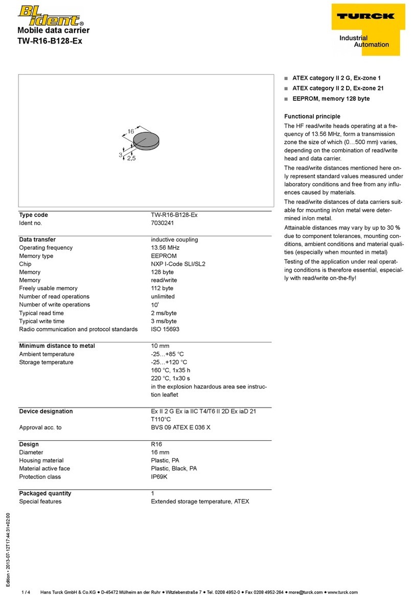
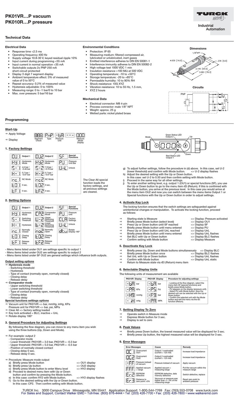
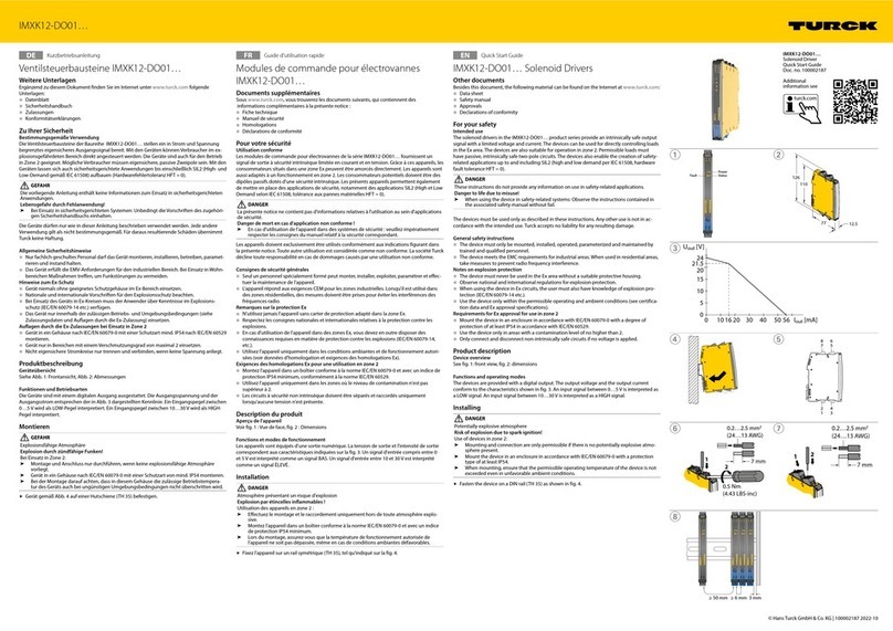
turck NIC...-M30 Series User manual

USER MANUAL MA1008
Published 10/15/2014
Inductive Coupler Manual

2
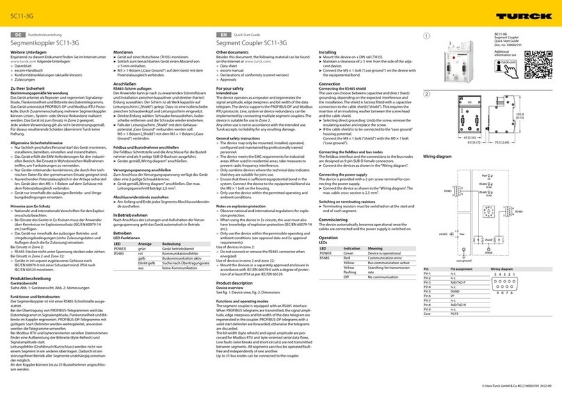
Inductive Coupler NIC…-M30
1 About This Manual 5
1.1 Target groups 5
1.2 Explanation of symbols 5
1.3 Feedback about these instructions 5
2 Notes on the product 6
2.1 Product identication 6
2.2 Scope of delivery 6
2.3 Standards and legal requirements 6
2.3.1 Classication of equipment acc. to SRD EN 300 440 6
2.4 Manufacturer and service 6
3 For Your Safety 7
3.1 Intended use 7
3.2 Safety instructions for inductive couplers 7
3.3 General safety notes 7
4 Product description 8
4.1 Device overview 8
4.1.1 Indication elements 8
4.2 Operating principle 9
4.3 Operating modes 9
4.3.1 Transfer of 2 standard PNP signals 9
4.3.2 IO-Link mode 10
4.3.3 Transfer of 8 standard PNP signals 10
4.4 Accessories 11
5 Mounting 11
5.1 Power with angle oset 12
5.2 Power with lateral oset 12
5.3 Distance between primary side and secondary side 12
6 Connecting 13
6.1 Transfer of 2 standard PNP signals 13
6.2 IO-Link mode 13
6.3 Transfer of 8 standard PNP signals 14
7 Commissioning 14
7.1 Setting IO-Link mode 14
8 Operation 14
9 Troubleshooting 14
9.1 Rectifying ambient interference 14
9.2 Rectifying device faults 15
Instructions for use - Inductive Coupler NIC...-M30 Contents

3
Inductive Coupler NIC…-M30
10 Maintenance 15
11 Repair 15
12 Decommissioning 15
13 Returning the devices 15
14 Specications 15
14.1 Technical data of the primary side 15
14.2 Technical data of the secondary side 16
14.3 Technical data of inductive transfer system 16

Hans Turck GmbH & Co. KG •
4
Instructions for use – Inductive Coupler NIC…-M30
1 About This Manual
This manual describes the setup, the functions and use of the product and helps you to operate the product for
its intended use. Read these instructions carefully prior to using the product. This will prevent the risk of personal
injury and damage to property. Keep these instructions safely during the service life of the product. If the product
is passed on, pass on these instructions as well.
TURCK accepts no liability for damage caused by failure to observe these instructions.
If you require further information or have questions about the device, contact TURCK or visit our website.
1.1 Target groups
These instructions must be read and followed by anyone entrusted with any of the following tasks:
■Unloading and in-house transport
■Unpacking and mounting
■Commissioning
■Setting
■Testing and maintenance
■Troubleshooting
■Disassembly and disposal
1.2 Explanation of symbols
The following symbols are used in these instructions:
WARNING
WARNING indicates a possible hazardous situation with the risk of death or serious injury if it is not prevented.
NOTE
NOTE indicates tips, recommendations and important information. The notes contain information, particular op-
erating steps that facilitate work and possibly help to avoid additional work resulting from incorrect procedures.
MANDATORY ACTION
This symbol denotes actions that the user must carry out.
RESULT OF ACTION
This symbol denotes the relevant results of actions and procedures.
1.3 Feedback about these instructions
We make every effort to ensure that these instructions are as informative and as clear as possible. If you have any
suggestions for improving the design or if some information is missing in the document, please send your sug-
gestions to the TURCK Service.

5
Notes on the product
Inductive Coupler NIC…-M30
2 Notes on the product
2.1 Product identication
Type code – NIC…-M30 inductive coupler
NIC P –M30 –IOL 2P8X H1141
NIC Functional principle
Functional principle
NIC non-flush inductive coupler
Type code inductive coupler
IOL Technology
Technology
IOL IO-Link
PComponent –
Component
Pprimary side (transmitter)
Ssecondary side (receiver)
M30 Design –
Design
M30 M30 x 1.5, threaded barrel
2 P 8 X Electrical version –
Indication
XLED
Voltage range
824 VDC,
short circuit protected
Output mode
PPNP
Number of channels
22 channels
88 channels
H1141 Electrical connection
Electrical connection
H1141 Integrated male
connector M12 x 1,
4-pole
0,3-RKC4.4T Pigtail: 0.3 m cable
connection with
straight female
connector, M12 x 1,
4-pole
0,3-RSC12T Pigtail: 0.3 m cable
connection with
straight male
connector, M12 x 1,
12-pole
Primary side Secondary side
NICP-M30-IOL2P8X-H1141 NICS-M30-IOL2P8-0,3-RKC4.4T
NICP-M30-8P8-0,3-RSC12T
2.2 Scope of delivery
The scope of delivery consists of the device and two M30 nuts for mounting.
2.3 Standards and legal requirements
The product has been built with latest state of the art technology and in accordance with recognized technical
standards.
The conformity of the product with the EU Directive 1999/5/EC (R&TTE) is ensured for the following aspects by
meeting the requirements of other EU Directives with these standards:
Aspect (see R&TTE-Richtlinie, Artikel/
Abschnitt EU-Directive Standards
Health & Safety (Art. 3(1)a)) LVD (2006/65/EC) EN 62311:2008
EMC (Art. 3(1)b)) EMC (2004/108/EC) EN 61000-6-2:2005
EN 61000-6-4:2007
+Amendment1:2011
Spectrum: Efficient Radio Spectrum
(Art.3(2))
EN 300 400-2 V1.4.1 (2010-08)
2.3.1 Classication of equipment acc. to SRD EN 300 440
The device complies with the following classifications according to SRD EN 300 440
■Receiver Category 3
■Generic Short Range Device

Hans Turck GmbH & Co. KG •
6
Instructions for use – Inductive Coupler NIC…-M30
2.4 Manufacturer and service
With almost 50 years of experience and an extensive know-how, we can support you in every project phase – from
the initial analysis right through to the tailored implementation and commissioning of your application. In the
TURCK product database you will find the right solution, whether this involves software tools for programming,
configuration or commissioning support, detailed data sheets or CAD data in almost 80 export formats – acces-
sible worldwide, in nine different languages, free of charge and without registration. You can access the Product
Database via the following address: www.turck.de/en
For further inquiries contact Application Suport:
■800.544.7769
■appsupport@turck.com
Or contact your local TURCK representative via the below link:
http://turck.us/Support/North_American_Sales_Channel/
3 For Your Safety
The product is designed according to the latest state of the art technology. Residual hazards, however, still exist.
Observe the following safety instructions in order to avoid hazards. TURCK accepts no liability for damage caused
by failure to observe these safety instructions.
3.1 Intended use
Inductive couplers consist of a primary side and a secondary side. The devices are used for the contactless and
bidirectional transfer of power and data between an air interface (max. 7mm) in industrial environments. The pri-
mary side supplies power to the secondary side through the air interface. The secondary side supplies in turn data
from the connected sensors as well as sensors and actuators connected in IO-Link mode.
The product must only be fitted, installed, operated and maintained by trained and qualified personnel. The ma-
chine designer, supervising engineer, machine builder and/or the maintenance electrician are responsible for en-
suring that the product is used in full compliance with all applicable regulations and standards.
3.2 Safety instructions for inductive couplers
WARNING
Possible risk of heating the devices
Risk of burns through contact with hot surfaces of the device!
Do not place any metal objects such as screw drivers in the electrical field between the primary and secondary
side.
3.3 General safety notes
Observe the following safety instructions in order to prevent danger to persons and property:
WARNING
The devices are not safety devices and must not be used for people or machine protection.
7
Product description
Inductive Coupler NIC…-M30
4 Product description
4.1 Device overview
36/5
62
77
M30 x 1,5
16,5
M12 x 1
LED
36/5
71,5
76,4
4
M30 x 1,5
16,5
44,6
ø 15
M12 x 1
Fig. 1: Left: Dimension drawing of NICP-M30-IOL2P8X-H1141; right: NICP-M30-8P8-0.3-RSC12T primary side,
NICS-M30-IOL2P8-0.3-RKC4.4T secondary side
The devices have a cylindrical housing style with an M30×1.5 male thread. An M12 connector (male) directly on
the housing is used to connect the NICP-M30-IOL2P8X-H1141 primary side. The NICP-M30-8P8-0.3-RSC12T pri-
mary side and the NICS-M30-IOL2P8-0.3-RKC4.4T secondary side are provided with a 0.3 m connection cable with
an M12 female connector (pigtail).
4.1.1 Indication elements
The NICP-M30-IOL2P8X-H1141 primary side is provided with an LED for status indication.
Status LED Meaning
LED continuously lit Data and power transfer OK
LED flashes at a frequency of 10Hz Secondary side missing, no communication between primary and secondary
side
LED flashes at a frequency of 1Hz The FOD function (Foreign Object Detection) is active. The FOD detects metal
foreign objects between the primary and secondary side. The power supply of
the device is switched off if the FOD detects foreign objects (see chapter 6.3,
page 14).

Hans Turck GmbH & Co. KG •
8
Instructions for use – Inductive Coupler NIC…-M30
4.2 Operating principle
Inductive couplers transfer power based on the principle of inductive coupling power transfer – ICPT. The oscilla-
tion frequency is 200kHz. Data is transferred on a carrier frequency of 2.4GHz.
Fig. 2: Block diagram
4.3 Operating modes
The inductive couplers can be used to transfer 2 or 8 standard PNP signals or can be run in IO-Link mode. Different
primary sides of the inductive coupler must be used depending on the operating mode.
4.3.1 Transfer of 2 standard PNP signals
To transfer 2 standard PNP signals, the devices NICP-M30-IOL2P8X-H1141 (primary) and NICS-M30-IOL2P8-0.3-
RKC4.4T (secondary) are required. The secondary side transmits with a connected splitter VB2P3-FSM4.4/2RK 4T-
0.3/0.3 (ident no. U-73266) 2 standard PNP signals to the primary side. The junction box is not required if sensors
with 2 PNP outputs (e.g. power clamps) are used.
Fig. 3: Setup example for transferring 2 standard PNP signals
Signal
processing Near field
DC/AC
converter
C/Q
DO
DC
C/Q
DI
DC
Power
Signal
processing
Near field
DC/AC
converter
Power
2,4 GHz
ICPT

9
Product description
Inductive Coupler NIC…-M30
4.3.2 IO-Link mode
The devices NICP-M30-IOL2P8X-H1141 (primary) and NICS-M30-IOL2P8-0.3-RKC4.4T (secondary) are required for
IO-Link mode. IO-Link mode provides a bidirectional IO-Link communication between an IO-Link master and an
IO-Link device via the air interface.
Fig. 4: Setup example for IO-Link communication
4.3.3 Transfer of 8 standard PNP signals
To transfer 8 standard PNP signals, the following devices are required:
■NICP-M30-8P8-0.3-RSC12T (primary)
■NICS-M30-IOL2P8-0.3-RKC4.4T (secondary)
■TBIL-M1-16DIP (I/O hub for IO-Link).
If the secondary side is connected to an I/O hub for IO-Link TBIL-M1-16DIP, up to 8 standard PNP signals can be
transferred via the inductive coupler. For this a PNP sensor is connected to the ports of the TBIL-M1-16DIP on chan-
nel A. On the primary side, the PNP sensor signals can be connected to a digital input card via the connector at the
device.
Fig. 5: Setup example for transferring 8 standard PNP signals

Hans Turck GmbH & Co. KG •
10
Instructions for use – Inductive Coupler NIC…-M30
4.4 Accessories
Dimension drawing Ident no. Type Description
C1 C3
C2 C4
C5
C6
C7
C8
73
107
44,7
32,2
150
16
25,2
ø 4,3
54
M12 x 1
27,4
M6814100 TBIL-M1-
16DIP
I/O hub for IO-link, 16 digital PNP inputs
M6814101
U0956-72
TBIL-M1-
8DOP
RS4.4T-J14
I/O hub for IO-link, 8 digital outputs
Jumper Plug Used With TBIL-M1-16DIP Hub
M6827386
M6827383
M6827216
BL67-4IOL
BL67-4DI-P
BL67-B-
1M23-19
IO-Link-1.1 master for the modular fieldbus system
BL67, 4 IO-Link ports and 4 programmable PNP ports
Digital input modular I/O card for use with NICP-M30-
8P8-0.3-RSC 12T
Base module for BL67-16DI-P
M6827385 BL20-E-4IOL IO-Link-1.1 master for the modular fieldbus system
BL20, 4 IO-Link ports and 4 programmable PNP ports
41
24
54
M12 x 1 16
USB-Mini
IN-DC
LED:
CH1 (C/Q)
CH2 (DI/DO)
Error
LED: PWR M6825482 USB-2-
IOL-0002
IO-Link-1.1 master with USB port,
1-chanel operation in IOL or SIO mode
L
U5302 RKC4.4T-2 Connection cable, female M12, straight, 4-pin, cable
length: 2 m, PVC jacket
L
U5264 RKC4.4T-2-
RSC4.4T
Extension cable, female M12, straight 4-pin, cable
length 2 m, male M12, straight 4-pin, PVC jacket
M23 x 1
≈ 56
ø 26
L
U-77150 RKC 12T-
2-CSM 19-12/
S90/S1247
Extension cable for use with NICP-M30-8P8-0.3-RSC
12T to connect to BL67-B-1M23-19 base. Female M12
straight 12 pin to male M23, cable length: 2m, TPU
jacket
5 Mounting
The maximum tightening torque of the housing nuts is 40 Nm.
Check whether the housing material and the degree of protection is sufficient in terms of resistance, vibration
resistance and cleaning for your application.
Align the front faces of the primary and secondary side to each other. Refer to the“Power with angle offset”
table (chapter 5.1), “Power with lateral offset” (chapter 5.2) and“Distance between primary side and secondary
side” (chapter 5.3).
Fit the device at the intended mounting location. Observe the minimum mounting distances.
40.0 [1.58]
M12x1
Ø14.5 [0.57]

11
Mounting
Inductive Coupler NIC…-M30
D
S
T
N
Distance
T 60mm
N 26.5mm
S 30mm
D 60mm
Fig. 6: Mounting distances
5.1 Power with angle oset
α
D
Distance D Angle α Power
2mm 7.5° 12W
4mm 15° 12W
5mm 20° 12W
7mm 25° 12W
8mm 30° 1W
Fig. 7: Angle offset
5.2 Power with lateral oset
M
D
Distance D Oset M Power
0mm 5mm 12W
2mm 5mm 12W
4mm 5mm 12W
5mm 3mm 12W
7mm 2mm 12W
8mm 1mm 1W
Fig. 8: Lateral offset between primary side (right) and secondary side (left)
5.3 Distance between primary side and secondary side
D
Distance D Power
0mm 12W
2mm 12W
4mm 12W
6mm 12W
7mm 12W
8mm 1W
Fig. 9: Distance between primary side (right) and secondary side (left)

Hans Turck GmbH & Co. KG •
12
Instructions for use – Inductive Coupler NIC…-M30
6 Connecting
6.1 Transfer of 2 standard PNP signals
Connect the sensors (e. g. to a 2-channel junction module VB2-FSM4.4-2FKM4).
Connect the secondary side NICS-M30-IOL2P8-0.3-RKC4.4T as per the terminal layout in Fig. 11 to a sensor.
Connect the primary side NICP-M30-IOL2P8X-H1141 as per the terminal layout in Fig. 10 via an M12 connec-
tion cable (e.g. RKC 4.4T-2) to a controller or a fieldbus device.
Contact Terminal layout Wiring diagrams
Contact 1 +24 VDC
1 24 VDC +
2 Output 2
3 GND –
4 Output 1
Contact 2 Output 2
Contact 3 GND
Contact 4 Output 1
Fig. 10: Terminal layout Primary side
Contact Terminal layout Wiring diagrams
Contact 1 +24 VDC
1 24 VDC +
2 Input 2
3 GND –
4 Input 1
Contact 2 Input 2
Contact 3 GND
Contact 4 Input 1
Fig. 11: Terminal layout Secondary side
6.2 IO-Link mode
NOTE
In IO-Link mode contact 2 cannot be used as a digital input or output.
Connect the secondary side NICS-M30-IOL2P8-0.3-RKC4.4T as per the terminal layout in Fig. 13 to an IO-Link
device.
Connect the primary side NICP-M30-IOL2P8X-H1141 as per the terminal layout in Fig. 12 via an M12 connec-
tion cable (e.g. RKC4.4T-2) to an IO-Link master.
Contact Terminal layout Wiring diagrams
Contact 1 +24 VDC
1 24 VDC +
2 n.c.
3 GND –
4 Output 1 & C/Q (IO-Link)
Contact 2 n. c.
Contact 3 GND
Contact 4 Output 1 & C/Q (IO-Link)
Fig. 12: Terminal layout Primary side
Contact Terminal layout Wiring diagrams
Contact 1 +24 VDC
1 24 VDC +
2 n.c.
3 GND –
4 Input 1 & C/Q (IO-Link)
Contact 2 n. c.
Contact 3 GND
Contact 4 Input 1 & C/Q (IO-Link)
Fig. 13: Terminal layout Secondary side

13
Commissioning
Inductive Coupler NIC…-M30
6.3 Transfer of 8 standard PNP signals
Connect the sensors to the respective ports of the I/O hub for IO-Link TBIL-M1-16DIP (Ident no. 6814100). Use
here channel A (contact 4).
Connect the secondary side NICS-M30-IOL2P8-0.3-RKC4.4T as per the terminal layout in Fig. 15 to the TBIL-M1-
16DIP IO-Link sensor hub.
Connect the primary side NICP-M30-8P8-0,3-RSC12T as per the terminal layout in Fig. 14 with a 12-pin M12
male connector (e.g. RKC12T-2-CSM 19-12/S90/S1247) to a fieldbus device or a PLC with suitable PNP inputs.
Contact Terminal layout Wiring diagrams
Contact 1 +24 VDC
Contact 2 GND
Contact 3 Output 1
Contact 4 Output 2
Contact 5 Output 3
Contact 6 Output 4
Contact 7 Output 5
Contact 8 Output 6
Contact 9 Output 7
Contact 10 Output 8
Contact 11 FOD Status: FOD active
Contact 12 Signal not OK Status: Secondary side not present
Fig. 14: Terminal layout Primary side
NOTE
When transferring 8 standard PNP signals, contact 2 cannot be used as a digital input.
Contact Terminal layout Wiring diagrams
Contact 1 +24 VDC
1 24 VDC +
2 n.c.
3 GND –
4 Input 1 & C/Q (IO-Link)
Contact 2 n. c.
Contact 3 GND
Contact 4 Input 1
Abb. 15:Terminal layout Secondary side
7 Commissioning
The device is automatically operational after the power supply is connected and switched on and after a power
up delay of 160ms.
7.1 IO-Link mode
Set the cycle time on the IO-Link master (min. 10ms).
The inductive coupler is operational.
8 Operation
On the primary side several components of the secondary side with the same configuration can also be operated
(so-called Dynamic Pairing). With power on the primary side a startup delay of 10ms must be expected.
9 Troubleshooting
9.1 Rectifying ambient interference
The device is provided with an FOD function (Foreign Object Detection). The FOD detects metal foreign objects
in the active area between the primary and secondary side. The device then automatically switches off the power
1 24 VDC +
2 GND
3 Output 1
4 Output 2
5 Output 3
6 Output 4
7 Output 5
8 Output 6
9 Output 7
10 Output 8
11 FOD
12 Signal NOK

Hans Turck GmbH & Co. KG •
14
Instructions for use – Inductive Coupler NIC…-M30
supply. The FOD status is indicated as follows:
Device FOD active
NICP-M30-IOL2P8X-H1141 LED flashes at a frequency of 1Hz.
NICP-M30-8P8X-0,3-RSC12T FOD status contact is set.
9.2 Rectifying device faults
If the device does not function as expected, first check whether ambient interference is present.
If this is not the case, a device fault is present. In this case, decommission the device and replace it with a new
device of the same type.
10 Maintenance
The devices are maintenance-free.
The active area between the primary side and the secondary side must be cleared occasionally of any metal con-
tamination (e.g. chips) in order to improve operation.
11 Repair
The device must not be repaired by the user. If the device is faulty, decommission it and send it to TURCK. Observe
here the specific warranty conditions agreed with the shipment.
12 Decommissioning
Remove the connection cable from the power supply and/or sensing devices.
Remove the connection cable from the primary side.
Remove the connection cable from the secondary side.
Undo the connections of the device or if necessary the mounting aid for the mounting area.
Undo if necessary the connection of the device to the mounting aid.
13 Returning the devices
If a device has to be returned, bear in mind that only devices with a decontamination declaration will be accepted.
This is available for download at http://www.turck.de/de/support_download.asp and must be completely filled
in, and affixed securely and weather-proof to the outside of the packaging.
14 Specications
14.1 Technical data of the primary side
Specications NICP-M30-IOL2P8X-H1141 NICP-M30-8P8-0,3-RSC12T
Operating voltage 24VDC ± 10 % 24VDC ± 10 %
Operating current 750 mA 750 mA
Nominal distance 0…7 mm 0…7 mm
Ambient temperature -20…+55 °C -20…+55 °C
Output function 4-wire PNP and IO-Link 12-wire PNP
Degree of protection IP67 and IP68 IP67 and IP68
Electrical connection M12 connector, 4-pin Connection cable, 0.3m, with M12
connector, 12-pin

15
Specications
Inductive Coupler NIC…-M30
14.2 Technical data of the secondary side
Specications NICS-M30-IOL2P8-0,3-RKC4.4T
Output voltage 24VDC ± 10 %
Output function 4-wire PNP and IO-Link
Ambient temperature -20…+55°C
Degree of protection IP67 and IP68
Output current 500 mA
Peak current output 2400 mA for 0.1 ms
Start time 10 ms
Electrical connection Connection cable, 0.3m, with male
M12 , 4-pin
14.3 Technical data of inductive transfer system
Specications Inductive transfer system
Standby time 160 ms
Standby power, coupled 4 W
Standby power, not coupled 1 W
IO-Link communication COM2/IO-Link 1.1.1, 38.4kBaud
Rotation 100 rpm
Other manuals for NIC...-M30 Series
1
This manual suits for next models
3
Table of contents
Other turck Industrial Equipment manuals

turck
turck EZ-track LT Q35 Series User manual

turck
turck IMXK12-DO01 Series User manual

turck
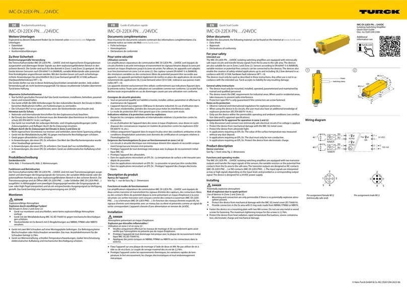
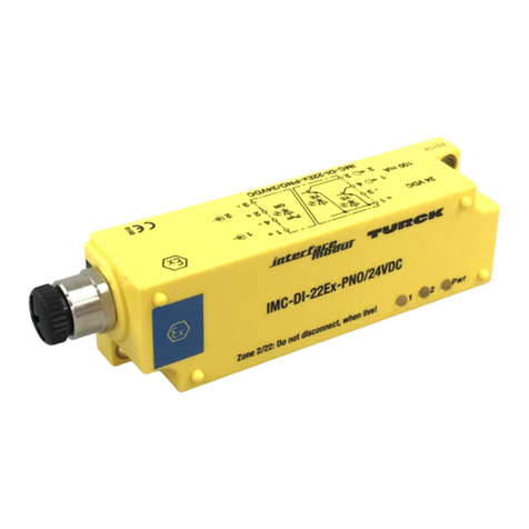
turck IMC-DI-22EX-PN 24VDC Series User manual

turck
turck BL ident TW-R16-B128-Ex User manual

turck
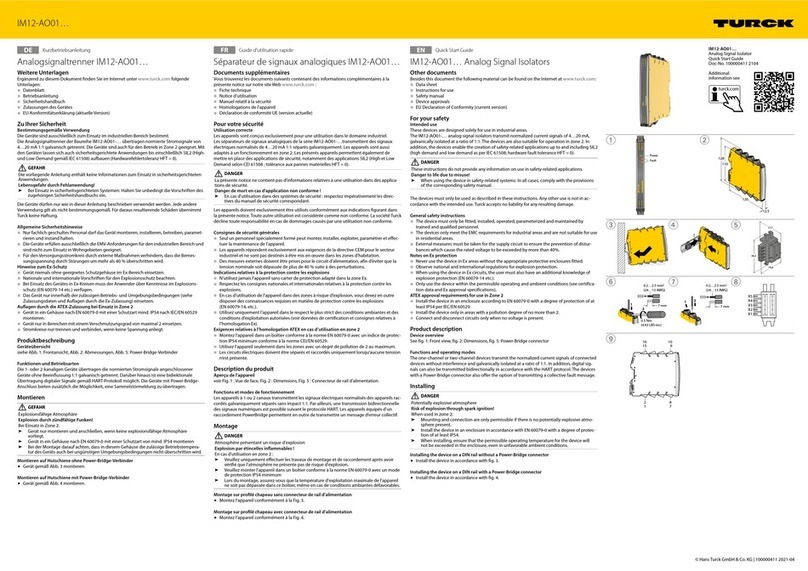
turck M12-AO01 Series User manual

turck
turck NIC EM30-IOL Series User manual

turck
turck IO-Link Master V1.1 User manual

turck
turck BL20 User manual

turck
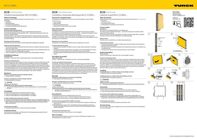
turck IM12-CCM03 Series User manual

turck
turck BC10-P30SR-VP4X2/3GD User manual