Southwestern Industries TRAK 2OP M11 Guide

Southwestern Industries, Inc.
2615 Homestead Place
Rancho Dominguez, CA 90220-5610 USA
T | 310-608-4422
F | 310-764-2668
Service Department: 800.367.3165
e-mail: sales@southwesternindustries.com | service@southwesternindustries.com | web: southwesternindustries.com
TRAKTM 2OP M11 Mill
Safety, Installation, Maintenance, Service and Parts List
Document: P/N 28170
Version: 111816

Copyright 2016, Southwestern Industries, Inc. All rights are reserved. No part of this
publication may be reproduced, stored in a retrieval system, or transmitted, in any form or by
any means, mechanical, photocopying, recording or otherwise, without the prior written
permission of Southwestern Industries, Inc.
While every effort has been made to include all the information required for the purposes of this
guide, Southwestern Industries, Inc. assumes no responsibility for inaccuracies or omission and
accepts no liability for damages resulting from the use of the information contained in this guide.
All brand names and products are trademarks or registered trademarks of their respective holders.

i
Southwestern Industries, Inc.
TRAK2OP Installation, Maintenance, Service & Part List Manual
Table of Contents
1.0 Safety
1.1 Safety Publications 1
1.2 Danger, Warning, Caution and Note
Labels and Notices Used in this Manual
1.3 Safety Precautions
2.0 System Description
2.1 Machine Specifications 8
2.2 Maximum Spindle Torque & HP
2.3 ProtoTRAK TMX Control Hardware
2.4 Machine Major Subassemblies
3.0 Installation
3.1 Lifting the 2 OP mill 18
3.2 Uncrating the 2 OP
3.3 Shortages: Inventory Checklist
3.4 Installation Checklist
3.5 Electrical Connections
3.6 Air Connections
3.7 Cleaning the 2 OP
3.8 Leveling Procedure
3.9 Lubrication
3.10 Moving the 2 OP Around the Shop
3.11 Cutting the Euclid Test Block
4.0 Troubleshooting by Symptom
4.1 Machine Related Problems 31
4.2 Motion Related Problems
4.3 Control Related Problems
4.4 Tool Changer (Carrier) Problems
4.5 Control Input or Output Problem
4.6 Measurement Problems
4.7 Machine Tool Problems
5.0 Diagnostics
5.1 The Machine Tool & Setup 48
5.2 The Mechanical Drive Train
5.3 Computer Module
5.4 Programming Panel
5.5 Axis Motors/Servos
5.6 Spindle Motor & AC Drive
5.7 Electrical
5.8 Tool Carrier Diagnostics
5.9 Pneumatic Diagnostics
5.10 Coolant Diagnostics
5.11 Service Codes
6.0 Replacement Procedures
6.1 Axis Motor Replacement (includes setting
motor index angles) 106
6.2 AC Spindle Drive Replacement
6.3 Computer Module Replacement
6.4 Linear Guide Replacement
6.5 Ballscrew Replacement –X Axis
6.6 Ballscrew Replacement –Y Axis
6.7 Ballscrew Replacement –Z Axis
6.8 Spindle Motor Replacement
6.9 Spindle Motor Wiring
6.10 Spindle Cartridge Replacement
6.11 Spindle/Motor Coupling Alignment
6.12 Automatic Tool Carrier (ATC) Replacement
6.13 Setting ATC Locations
6.14 Coolant Pump Replacement
6.15 Bleeding Air from Tool Unclamp Cylinder Oil System
6.16 Programming Panel Replacement
6.17 Home Switch Replacement
6.18 Spindle Motor Encoder Replacement
6.19 X, Y & Z Home Switch Adjustments
6.20 Adjusting the Drawbar Bumpout
6.21 Servo Drive Replacement
6.22 Setting Spindle Orientation –Service code 510
7.0 Maintenance
7.1 Calibration 136
7.2 Backlash Compensation
7.3 Periodic Maintenance
Assembly Drawings (rear of manual)
27500-1 Rev B Spindle Head Assembly
27520-1 Rev B X Axis Drive Train
27540-1 Rev D Z Axis Drive Train
27542-1 Rev B Base Frame Assembly
27557 Rev B Coolant System
27563-1 Rev D Pneumatic System
27564-1 Rev E Y Axis Drive Train
27568-1 Rev D Enclosure Assembly
27587-1 Rev A ATC Assembly
27591-1 Rev B Lubrication System
27600-2 Rev C Machine Assembly
27605-1 Rev A Single Phase Option
27621-2 Rev C Electrical Cabinet Assembly
27648-2 Rev C System Diagram
27650-2-SCH Rev F (D size) Electrical Schematic
27658-1 Rev A Home Switch Assembly
27682 Rev A Cover Assembly
27830-1 Rev C Spindle Cartridge Assembly
28091-1 Rev C 440 Volt Option
28137 Rev C Indexer Ready Option
28156 Rev A Enclosure Assembly –Servo Drives
28160 Rev B Programming Panel Assembly

1
Southwestern Industries, Inc.
TRAK2OP M11 Installation, Maintenance, Service, & Part List Manual
1.0 Safety
The safe operation of the 2 OP Mill depends on its proper use and the precautions taken by each operator.
Read and study this manual and the 2 OP Programming, Operating, and Care Manual. Be certain
every operator understands the operation and safety requirements of this machine
before
its use.
Never run the machine with enclosure doors open
Always wear safety glasses and safety shoes.
Always stop the spindle and check to ensure the CNC control is in the stop mode before changing or
adjusting the tool or workpiece.
Never wear gloves, rings, watches, long sleeves, neckties, jewelry, or other loose items when
operating or around the machine.
Use adequate point of operation safeguarding. It is the responsibility of the employer to provide and
ensure point of operation safeguarding per OSHA 1910.212 - Machining centers.
1.1 Safety Publications
Refer to and study the following publications for assistance in enhancing the safe use of this machine.
Safety Requirements for Machining Centers and Automatic, Numerically Controlled Milling,
Drilling and Boring Machines (ANSI B11.22-2002) (R2007) & (ANSI B11.23-2002 (R2007). Available from
The American National Standards Institute, 1819 L Street N.W., Washington D.C. 20036
Concepts And Techniques Of Machine Safeguarding (OSHA Publication Number 3067). Available from
The Publication Office - O.S.H.A., U.S. Department of Labor, 200 Constitution Avenue, NW, Washington, DC
0210.
1.2 Danger, Warning, Caution, and Note Labels & Notices As Used
In This Manual
DANGER - Immediate hazards that will result in severe personal injury or death. Danger labels on the
machine are red in color.
WARNING - Hazards or unsafe practices that
could
result in severe personal injury and/or damage to the
equipment. Warning labels on the machine are orange in color.
CAUTION - Hazards or unsafe practices, which
could
result in minor personal injury or equipment/product
damage. Caution labels on the machine are yellow in color.
NOTICE- Call attention to specific issues requiring special attention or understanding.
2
Southwestern Industries, Inc.
TRAK2OP M11 Installation, Maintenance, Service, & Part List Manual
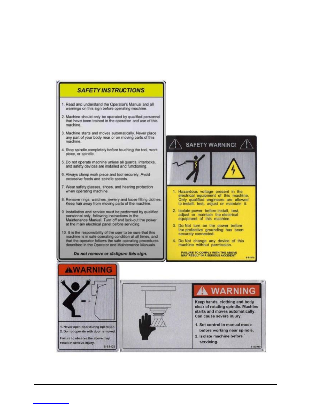
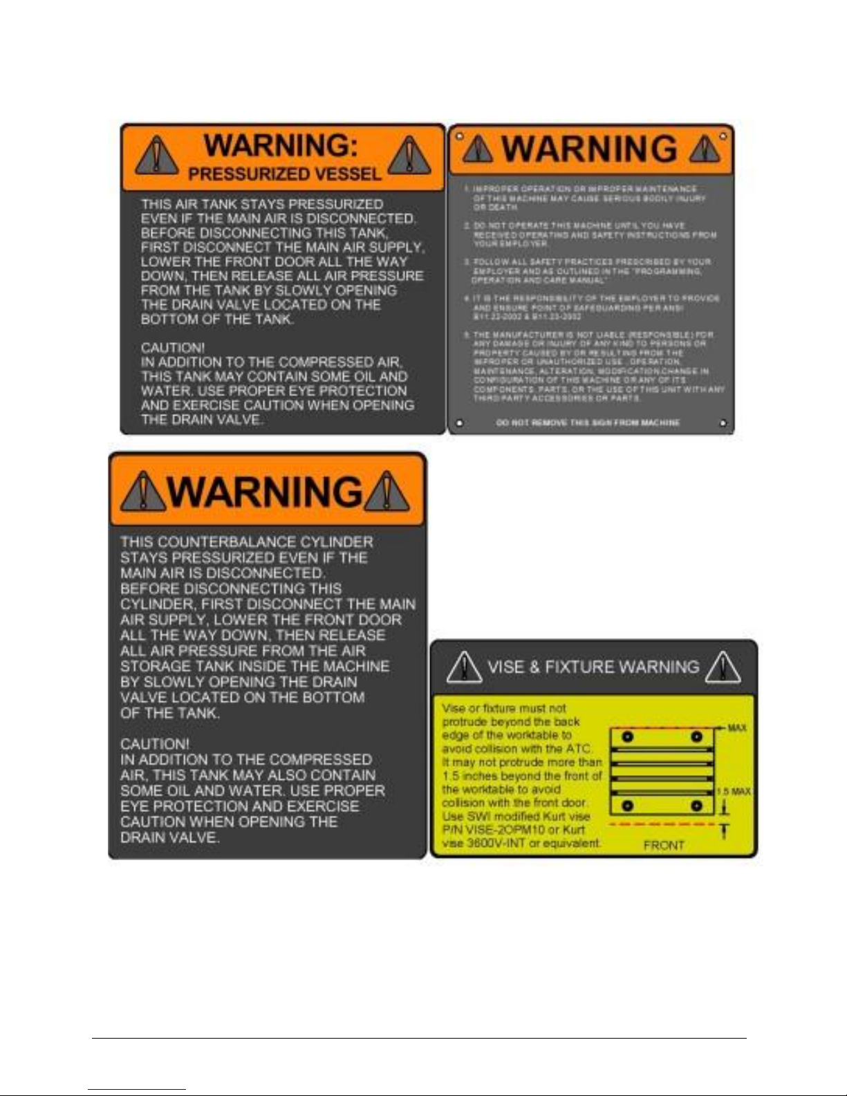
Safety & Information Labels Used On The
TRAK 2 OP Milling Machine
It is forbidden by OSHA regulations and by law to deface, destroy or remove any
of these labels
3
Southwestern Industries, Inc.
TRAK2OP M11 Installation, Maintenance, Service, & Part List Manual

4
Southwestern Industries, Inc.
TRAK2OP M11 Installation, Maintenance, Service, & Part List Manual

5
Southwestern Industries, Inc.
TRAK2OP M11 Installation, Maintenance, Service, & Part List Manual

6
Southwestern Industries, Inc.
TRAK2OP M11 Installation, Maintenance, Service, & Part List Manual
1.3 Safety Precautions
1. Do not operate this machine before the 2 OP Installation, Maintenance, Service and Parts List
Manual,Operating & Care Manual have been studied and understood.
2. Do not run this machine without knowing the function of every control key, button, knob, or handle.
Ask your supervisor or a qualified instructor for help when needed.
3. Protect your eyes. Wear approved safety glasses (with side shields) at all times.
4. Don't get caught in moving parts. Before operating this machine remove all jewelry including
watches and rings, neckties, and any loose-fitting clothing.
5. Keep your hair away from moving parts. Wear adequate safety headgear.
6. Protect your feet. Wear safety shoes with oil-resistant, anti-skid soles, and steel toes.
7. Take off gloves before you start the machine. Gloves are easily caught in moving parts.
8. Remove all tools from the machine before you start. Loose items can become dangerous flying
projectiles.
9. Never operate a milling machine after consuming alcoholic beverages, or taking strong medication, or
while using non-prescription drugs.
10. Protect your hands. Stop the machine spindle and ensure that the CNC control is in the stop mode:
Before changing tools
Before changing parts
Before you clear away the chips, oil or coolant. Always use a chip scraper or brush.
Do not used compressed air to clean the machine.
Before you make an adjustment to the part, fixture, coolant nozzle or take measurements.
Do not attempt to disable any safety interlock. Never reach around a safeguard.
11. Protect your eyes and the machine as well.
12. Disconnect power to the machine before you change belts, pulley, and gears.
13. Keep work areas well lighted. Ask for additional light if needed.
14. Do not lean on the machine while it is running.
15. Prevent slippage. Keep the work area dry and clean. Remove the chips, oil, coolant and obstacles of
any kind around the machine.
16. Avoid getting pinched in places where the table, saddle or spindle head create "pinch points" while in
motion.
17. Securely clamp and properly locate the workpiece in the vise, on the table, or in a fixture. Use stop
blocks to prevent objects from flying loose. Use proper holding clamping attachments and position
them clear of the tool path.
18. Use correct cutting parameters (speed, feed, depth, and width of cut) in order to prevent tool
breakage due to premature wear.

7
Southwestern Industries, Inc.
TRAK2OP M11 Installation, Maintenance, Service, & Part List Manual
19. Use proper cutting tools for the job. Pay attention to the rotation of the spindle: As viewed from
above, left hand tool for counterclockwise rotation of spindle, and right hand tool for clockwise
rotation of spindle.
20. To prevent damage to the workpiece or the cutting tool, never start the machine (including the
rotation of the spindle) if the tool is in contact with the part.
21. Check the direction (+ or -) of movement of the table when using the jog feature, clockwise rotation
of the EHW moves the axis in the positive direction, counterclockwise in the negative direction.
22. Don't use dull or damaged cutting tools. They break easily and become airborne. Inspect the
sharpness of the edges, and the integrity of cutting tools and their holders. Use proper length for the
tool.
23. Inspect the retention knobs for damage or excessive wear before each use.
24. Large overhang on cutting tools when not required result in accidents and damaged parts.
25. Prevent fires. When machining certain materials (magnesium, etc.) the chips and dust are highly
flammable. Obtain special instruction from your supervisor before machining these materials.
26. Prevent fires. Keep flammable materials and fluids away from the machine and hot, flying chips.
Warning
Retention knobs come in a wide variety of designs, however they often look similar and appear to
be interchangeable, but they are not. Use only the knob that the 2 OP mill is designed to use.
The use of the incorrect knob, or the incorrect usage of a knob, may result in injury or property
damage. To ensure the correct knob is chosen, please refer to section 2.4.4, System Description
section of this manual

8
Southwestern Industries, Inc.
TRAK2OP M11 Installation, Maintenance, Service, & Part List Manual
2.0 System Description
Read and understand this entire installation section before beginning the installation procedure.
2.1 Machine Specifications
Please see the drawing on the next page for a layout of the TRAK 2OP machine.
Overall Machine Dimensions
Width of machine 30.5”
Depth of machine 52”
Height of mill with head all the way up 101”
Minimum height to fit mill through doorway 92”
(Z cable carrier collapsed, resistor cover and resistors removed)
Machine Specifications
Table Dimensions
Table size
18” x 15”
Number of tee slots and pitch
4 @ 63 mm
Tee slot width
0.630” or 16 mm
Table maximum load
500 lbs.
Ball Lock ® hold down force
2250 lbs @ 35 in/lbs of
torque
Machine Weight
~2825 lbs
Machine Shipping Weight
~3175 lbs
Travel
X-axis
14”
Y-axis
18” (12” of machining travel)
Z-axis
17”
Maximum distance from spindle nose table surface
20.25”
Minimum distance from spindle nose table surface
2.75”
Maximum swing clearance from spindle center to column
14”
Maximum Rapid speed X, Y & Z-axis, inches per minute
600
Spindle
Tool holder type
BT30
Spindle nose diameter
2.2” or 56 mm
Maximum RPM
6000
Automatic Tool Carrier
Tool Capacity
8
Maximum tool diameter
2 or ~50 mm
Retention knob
See section 3.4.4
Longest Tool that can be use in ATC –length measured from
bottom of drive dog flange on holder
6.75”
Air Requirements
Pressure
90 psi
Quality
CFM
SCFM
Air dried/filtered water
separator upstream of the
machine
2.5 @ 90 psi
18

9
Southwestern Industries, Inc.
TRAK2OP M11 Installation, Maintenance, Service, & Part List Manual

10
Southwestern Industries, Inc.
TRAK2OP M11 Installation, Maintenance, Service, & Part List Manual
2.2 Maximum Spindle Torque and Horsepower
The following graphs illustrate the continuous and peak torque vs RPM and horsepower vs RPM
for the 2 OP M11 machine at the spindle. Peak torque and horsepower values can only be
attained for a short period of time before the spindle drive will fault out to protect the motor.
Note - Maximum work capacities are dependent on a lot of variables that cannot be controlled by
the machine manufacturer. Each one of the following will have an impact on the above
0
2
4
6
8
10
12
14
16
0 1000 2000 3000 4000 5000
Torque (ft-lbs)
RPM
Torque vs RPM
Continuous Torque
Peak Torque

11
Southwestern Industries, Inc.
TRAK2OP M11 Installation, Maintenance, Service, & Part List Manual
numbers: speeds, feeds, cutter, cutter sharpness, material, setup, coolant and machine
adjustments.
2.3 ProtoTRAK TMX Control Hardware
2.3.1 Programming Panel Assembly
The programming panel assembly on the 2 OP is mounted to the front right side of the machine.
The panel consists of the program overlay, electronic handwheel (EHW), 5.7” LCD and a servo on
button. There are 2 USB ports mounted on the right side of the machine next to the
programming panel. They are used to save programs and/or plug in a keyboard and mouse.
There are 6 cables that route from the programming panel to the computer module. They are
the VGA cable, 2 USB cables, COM port cable, overlay power cable and EHW cable. The VGA
cable carries video signals from the computer module to LCD controller board. The LCD interface
board gives the user the ability to modify the brightness, color and position of the image. The
USB cables extend 2 of the USB ports on the computer module up to the right side of the
machine, next to the programming panel. The COM port provides the communication between
the computer and the Overlay Interface board. The Overlay power cable provides power to the
LCD and Overlay Interface board, it also feeds back the critical keys (GO, STOP, etc) to the
computer module. The EHW cable carriers the signals from the EHW down to the computer
module.
2.3.2 Electrical Cabinet
The electrical cabinet is found at the rear of the machine. The electrical cabinet contains the
main control hardware for the machine. The main components are the computer module and AC
spindle drive. See drawing 27621-2 at the rear of the manual.
2.3.3 Computer Module
The computer module is the heart and soul of the machine. All of the inputs and outputs are fed
through this module. The computer module controls the programming panel assembly, AC
spindle drive, servo drives, motor signals and feedback and all the inputs and outputs. Inside of
the computer module is a motherboard, motion control board and an applications board along
with a power supply.
The computer module also contains 2 USB ports. Both USB ports extend with 2 cables to the
front of the machine to ease access from the front of the machine.
2.3.4 Servo Motors
The TRAK 2OP mill uses 3 servo motors with servo drives to run the X, Y and Z axes. The motors
for the X and Y axis produce 21 in-lbs of continuous torque and 63 in-lbs of peak torque. The Z
axis motor produces all produces 28 in-lbs of continuous torque and 84 in-lbs of peak torque.
The servo motors run off of 220 volt single phase power.
2.3.5 Servo Drives
The TRAK 2OP mill uses 3 servo amps that are mounted in an enclosure that is mounted to the
top of the machine. The servo amps are the same for both the X and Y axis. The Z axis uses a
larger servo amp to drive the larger Z axis motor. A separate braking resistor is part of the Z axis
servo amp circuit to dissipate heat generated when the motor is decelerating. The resistor is
mounted to the top of this enclosure.

12
Southwestern Industries, Inc.
TRAK2OP M11 Installation, Maintenance, Service, & Part List Manual
2.4 Machine Major Subassemblies
2.4.1 Spindle
The spindle is contained within a cartridge and BT30 tool holders must be used. The spindle
bearings are permanently lubricated and require no additional attention by the user. The spindle
has an air purge system that is automatically activated during the tool change sequence; it blows
air down the spindle to prevent chips from being trapped between the holder and spindle taper.
The spindle cartridge design is also pressurized by air to prevent contaminants from getting up
inside the spindle. A spindle ring is also attached to the bottom of the spindle via the drive dogs
and prevents debris like coolant from getting up inside the spindle.
2.4.2 Spindle Motor & Drive
The spindle motor is 3 HP and directly drives the spindle via a coupling. The RPM range for this
machine is 50 to 6000 RPM.
2.4.3 Automatic Draw Bar Assembly
The automatic drawbar is an assembly consisting of an air cylinder and an actuator that
unclamps the tool. Tooling is changed by means of the Automatic Tool Changer (ATC), or can be
done manually by pressing and holding the “Unclamp” button. Tools are clamped when the
button is released. A clamping force of approximately 1000 lbs is generated to clamp the
toolholder to the spindle. The Automatic Draw Bar Assembly uses full system air and hydraulic oil
and requires no adjustment. There is an oil reservoir for the hydraulics that should be monitored
on a regular basis. If there is a leak in the system the oil in this reservoir will go down. This leak
will need to be fixed. This oil cup is found on top of the machine behind the spindle motor.
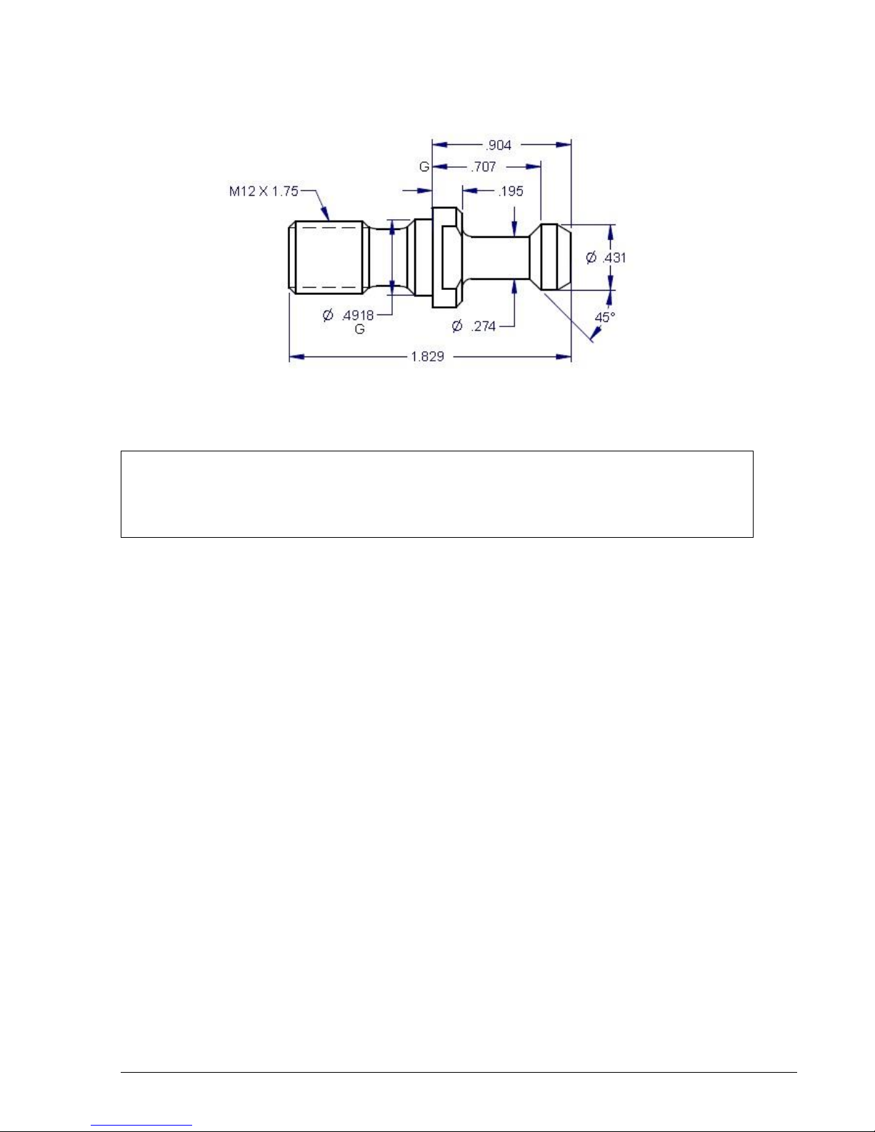
2.4.4 Retention Knobs
The TRAK 2OP Mill uses BT30 retention knobs as shown in Figure 2.4.4a. Tightening to the proper
torque value is important for all retention knobs. Please see the retention knob manufacturer for
the proper torque. You can order these retention knobs from Southwestern Industries under
part number RETN KNOB-2OPM11. Our retention knobs should be torqued to 30 ft-lbs. It should
be noted that lesser quality retention knobs will be torqued to something less than this.
Warning!
The spindle unit is not field serviceable. If the bearings go bad the entire
spindle cartridge will be replaced.
13
Southwestern Industries, Inc.
TRAK2OP M11 Installation, Maintenance, Service, & Part List Manual
Figure 2.4.4a
Warning!
Retention knobs come in a wide variety of designs, however they often look similar and appear to
be interchangeable, but they are not. Use only the knob that the 2 OP mill is designed to use.
The use of the incorrect knob, or the incorrect use of a knob, may result in injury and/or damage
to the mechanism.
2.4.5 Tool Changer (Carrier)
The tool changer is an 8 station mechanism that is actuated along the Y axis. It is hidden from
view while the machine is cutting. The ATC mechanism slides forward on the Y axis linear guides
and is actuated via an air cylinder.
2.4.6 Drive Train, Axes
Each axis (X, Y and Z) rides on precision linear guideways, with four preloaded recirculating ball
carriages. Each axis is moved via a 6 mm pitch ballscrew. The axis motors drive each axis via a
timing belt except on the Z axis where it is directly driven.
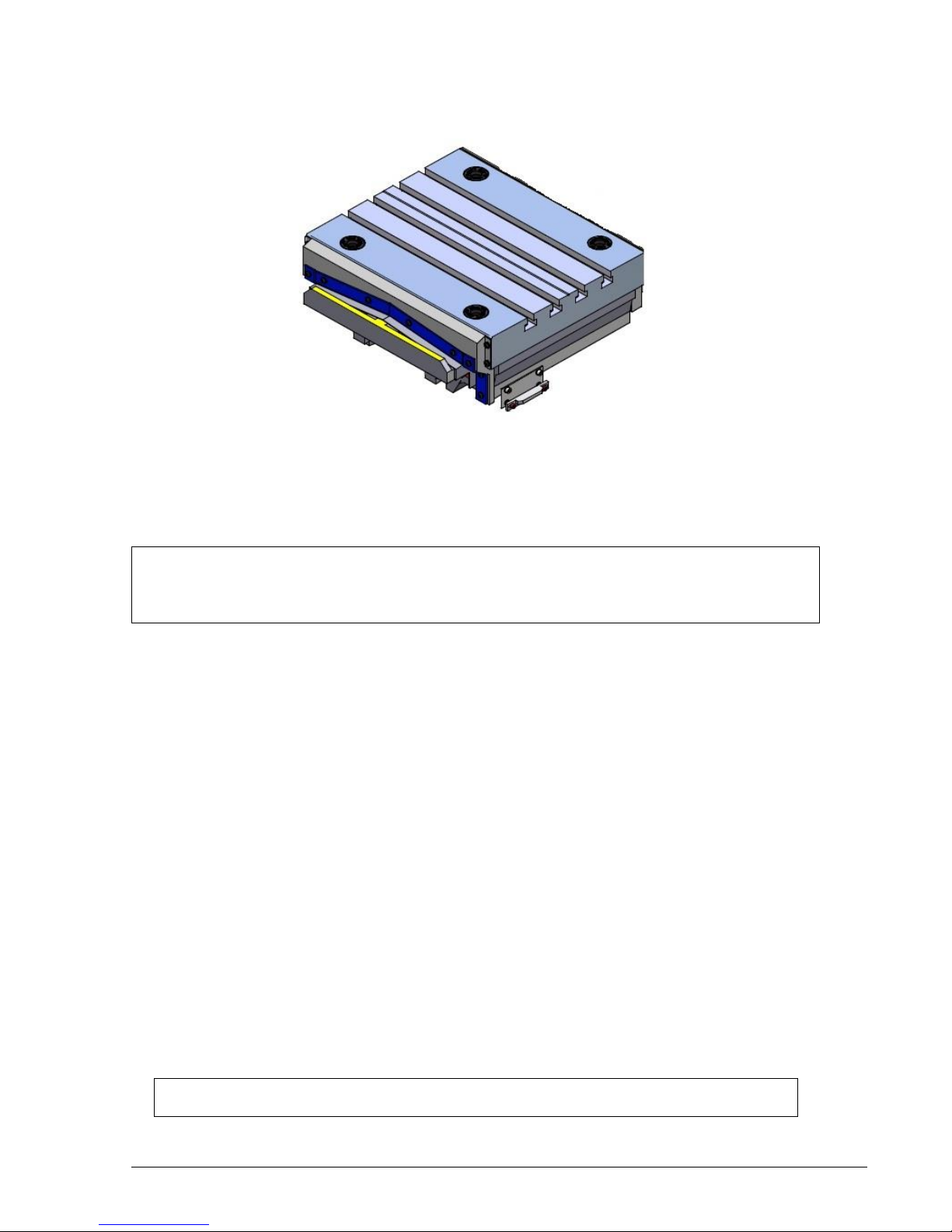
2.4.7 Worktable
The 2 OP table utilizes Ball Lock® technology as well as conventional T-bolt construction. Each
Ball Lock mechanism has a hold-down force of 2250 lbs when 35 in/lbs of torque is applied to the
screw. The software on the 2 OP mill allows the user to save the X and Y location of your
program relative to the lower left hand corner ball lock. See the programming manual for more
information. There are 4 ball lock receivers mounted in the table and they are separated by 12”.
The front 2 ball lock receivers are to be used to locate your fixture and the rear two are for
clamping purposes.
14
Southwestern Industries, Inc.
TRAK2OP M11 Installation, Maintenance, Service, & Part List Manual
Figure 2.4.7a
2.4.8 Home switches
Each axis has a home switch which is used to home the mill. The machine must be homed each
time the control is powered on.
Warning
It is not recommended that the position of the home switches be changed. They are preset at
the factory and should require no additional adjustments. Should any major adjustments be
done, service codes 500, 505, and 520 may need to be performed.
2.4.9 Lubrication System
The automatic lubricating system is a centralized system. It is located on the left side of the
machine. While the system is automatic, it is recommended that after long idle periods, the
machine be manually lubricated by using service code 300.Cycle the lube pump two to three
times. The lubrication reservoir should be maintained on a daily basis, filling only with high
quality lubricating oil. See section 3.9
2.4.10 Coolant and Coolant Wash System
The coolant and coolant wash system uses 1 pump to provide coolant to the work and also to
wash chip away from the area where the ATC comes out. Wash areas can be controlled by the
flexible coolant lines found at the base of the enclosure.
The coolant tank holds approximately 15 gallons of coolant.
See drawing 27557 at the rear of the manual for the coolant system.
2.4.11 Pneumatic System
The machine requires a supply of compressed air between 85-100 psi with a recommended air
supply of ½” I.D, minimum is 3/8” ID. Air pressure to pneumatic components, the ATC slide
mechanism, and air purge (internal spindle) can be controlled individually by means of the
adjusting valves located at the back of the 2 OP mill. See drawing 27563-1 for an overview of
the pneumatic system.
CAUTION!
Always Observe Low Air Pressure and Low Oil Level Warnings

15
Southwestern Industries, Inc.
TRAK2OP M11 Installation, Maintenance, Service, & Part List Manual
2.4.12 Enclosure Doors
The front door has an electro-mechanical safety interlock that must be engaged when running a
CNC program. If the door is opened during a machining operation, the program will be shut
down. This includes the axis motors and spindle.
The enclosure is also equipped with left and right doors that are bolted in place.
2.4.13 Status Light
The machine has a status light attached to the top of the machine to give the user status of what
is going on. The lights perform as follows:
a. The green light is illuminated when the machine is running a program.
b. The green light is flashing once per second when the operator input is required, like when a
part needs to be changed.
c. The green light flashes 3 times per second when a fault condition exists.
2.4.14 Chip Removal
The chip pan is located in the front of the mill. To remove, lift up on the pan and pull forward.
2.4.15 Work Lamp
The 2 OP mill comes equipped with a fluorescent work lamp, which comes on automatically
when the power is turned on.
2.4.16 Transformer
The TRAK 2OP mill must be ordered for 200 to 240 or 400 to 480 volts. A transformer outputs
115 and 24 volts. During the installation of the machine, the wires to the transformer may need
to be moved to adjust the output voltage. From the factory the wires on the transformer will be
place on the 220 or 440 volt tap and 115 volt tap on the output side. It should be noted that the
transformer is physically different for 220 volt machines versus 440 volt machines.
Warning
The input voltage to the machine should not exceed 240 or 480 volts. The spindle
inverter is not rated for voltages higher than this. If the shop has voltages that
exceed these numbers, they will need a step down transformer to lower the voltage.
Voltages higher than this may void your warranty.
DANGER
You must turn the power off to the machine before adjusting the wires on the
transformer. Failure to do so may cause death by electrocution.
Figure 2.4.17a shows the terminal blocks where you can switch the wiring. For example, the
machine is most likely shipped from the factory with the wire in the 220 volt terminal. This wire
needs to be moved to the 200 or 240 terminal if the input voltage to the machine measures this
amount.
CAUTION!
Do not Attempt to Disable or Override the Safety Interlock.

16
Southwestern Industries, Inc.
TRAK2OP M11 Installation, Maintenance, Service, & Part List Manual
Figure 2.4.17a –Transformer used on 220 volt machines
Figure 2.4.17b shows the terminal blocks for a 440 volt machine where you can switch the
wiring. For example, the machine is most likely shipped from the factory with the wire in the 440
volt terminal. This wire needs to be moved to the 400 or 480 terminal if the input voltage to the
machine measures this amount. The 380 volt terminal will most likely not be used on USA
machines.
Figure 2.4.17b –Transformer used on 440 volt machines
Please see drawing 27648-2 at the rear of the manual for more information.

17
Southwestern Industries, Inc.
TRAK2OP M11 Installation, Maintenance, Service, & Part List Manual
2.4.17 Single Phase Power Option
The TRAK 2OP mill has an optional single phase option for 220 volts. It needs to be noted that
running the machine on single phase power reduces the spindle power by about 40% as
compared to 3 phase 220 volt power. In other words, the spindle will not produce 3 HP. A
different style electric cord plug is used with single phase power. As part of the single phase kit,
we will provide an adaptor cable that allows the user to plug the machine into a 3 phase 220 volt
power connector. Please note that the machine will still only run on single phase power with this
adaptor. In order to convert the machine back to 3 phase power, a number of changes need to
be done to the machine. See section 3.5 for an illustration of what that plug looks like.
Table of contents
Other Southwestern Industries Power Tools manuals


