Soyal AR-721HV3 User manual

RFID CONTROLLER
BUILD IN READER
MANUAL
AR-721HV3
AR-721HV3-1356
2005/06/01

Table of Contents
Page
1 Introduction ---------------------------------------------------------------------------- 2
2 Features ---------------------------------------------------------------------------- 2
3 Specification --------------------------------------------------------------------------- 3
4 Installation Notice -------------------------------------------------------------------------- 4
5 Front Panel Indicators ----------------------------------------------------------------------- 7
6 Access Mode -------------------------------------------------------------------------- 8
User can select one of the following access modes ----------------------------- 8
AR-721HV3/1356 --------------------------------------------------------------------- 8
Duress function --------------------------------------------------------------------- 9
Force on/off Code (4 sets, 4 digits) ----------------------------------------------- 9
7 Function Default Value ---------------------------------------------------------------------- 11
8 Wiring ---------------------------------------------------------------------- 12
9 Installation Diagram ----------------------------------------------------------------------- 13
10 Installation ----------------------------------------------------------------------- 24
11 Troubleshooting ---------------------------------------------------------------------- 24
12 Return of Products ----------------------------------------------------------------------- 24
13 Warranty ------------------------------------------------------------------------ 25
※Removable CPU ----------------------------------------------------------------------- 25
14 Mode 4 Easy Guide ------------------------------------------------------------------------- 26
15 Mode 8 Easy Guide ------------------------------------------------------------------------- 30
16 Mode 6 Easy Guide ------------------------------------------------------------------------- 31
17 Mode 7 Easy Guide ------------------------------------------------------------------------- 33
18 Special Design ------------------------------------------------------------------------- 35
19 Transponder Record Table ---------------------------------------------------------------- 38
19.1 For AR-721H4, AR-721H7 and AR-721H8 ------------------------------------ 38
19.2 For AR-721H6 ------------------------------------------------------------------------- 39
20 FAQ ------------------------------------------------------------------------ 40
1

1. INTRODUCTION
Getting to know your SOYAL Proximity Reader….
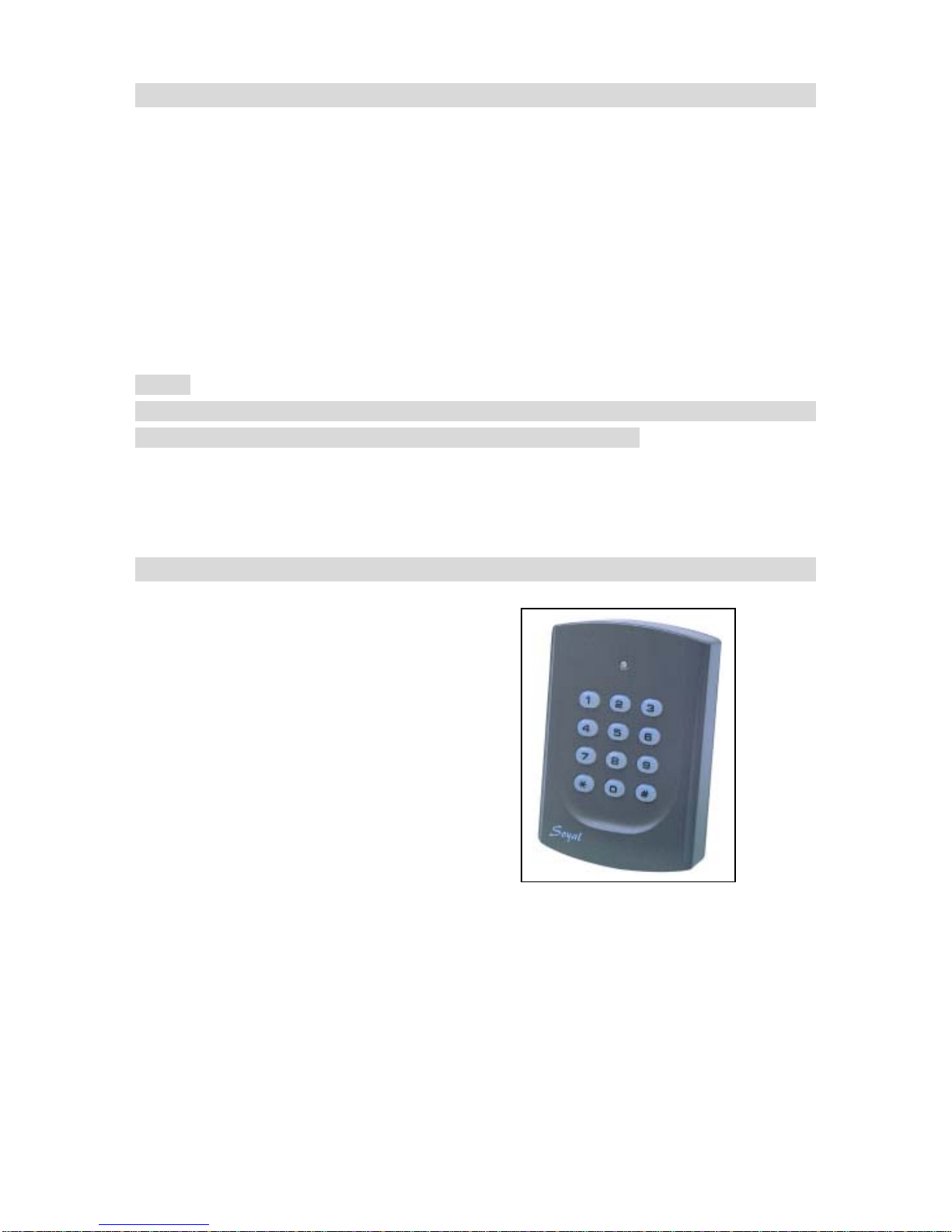
The AR-721HV3 &AR-721HV1356 are smart single door controller. It built-in a 6” RF
reader and an external reader port for exit or anti-pass-back use. It can work standalone
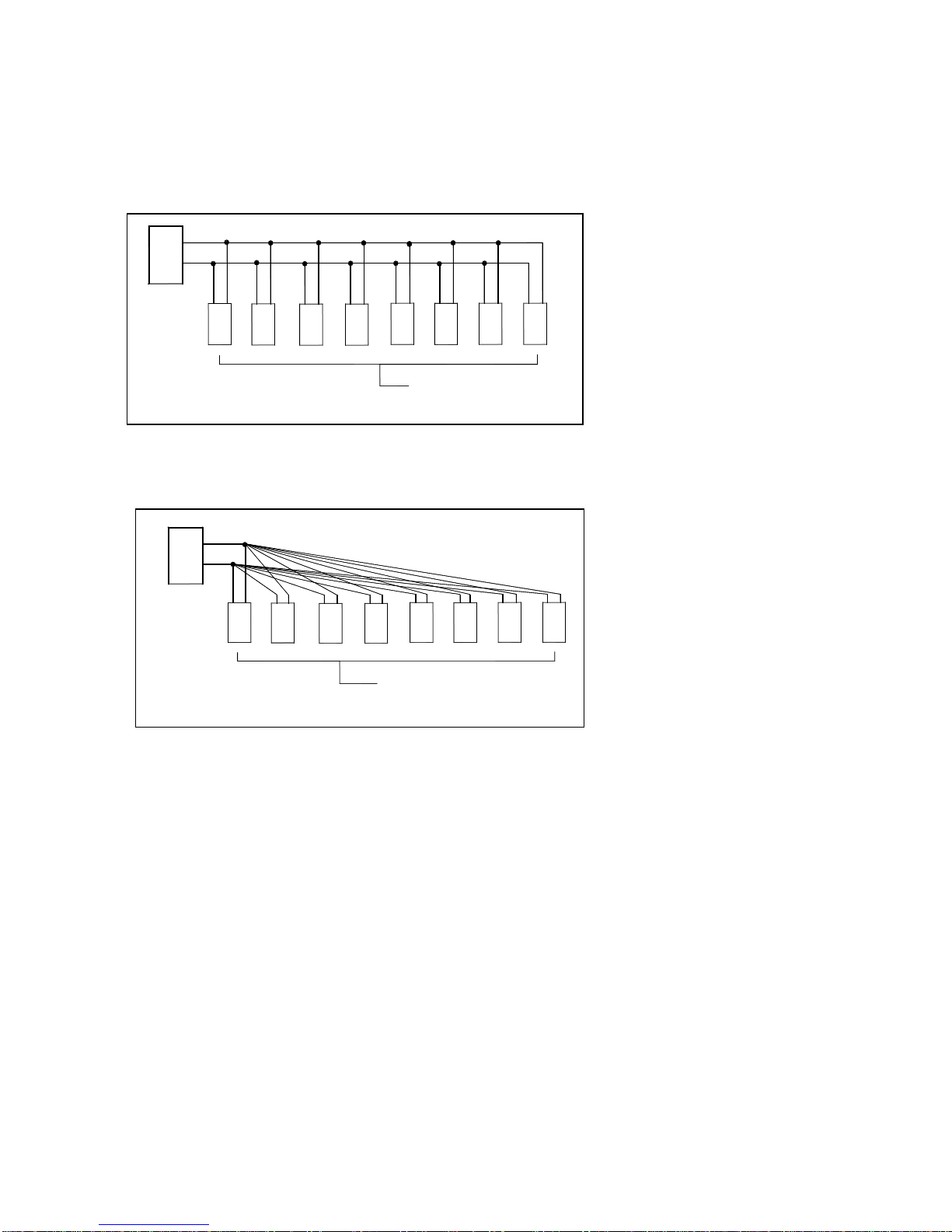
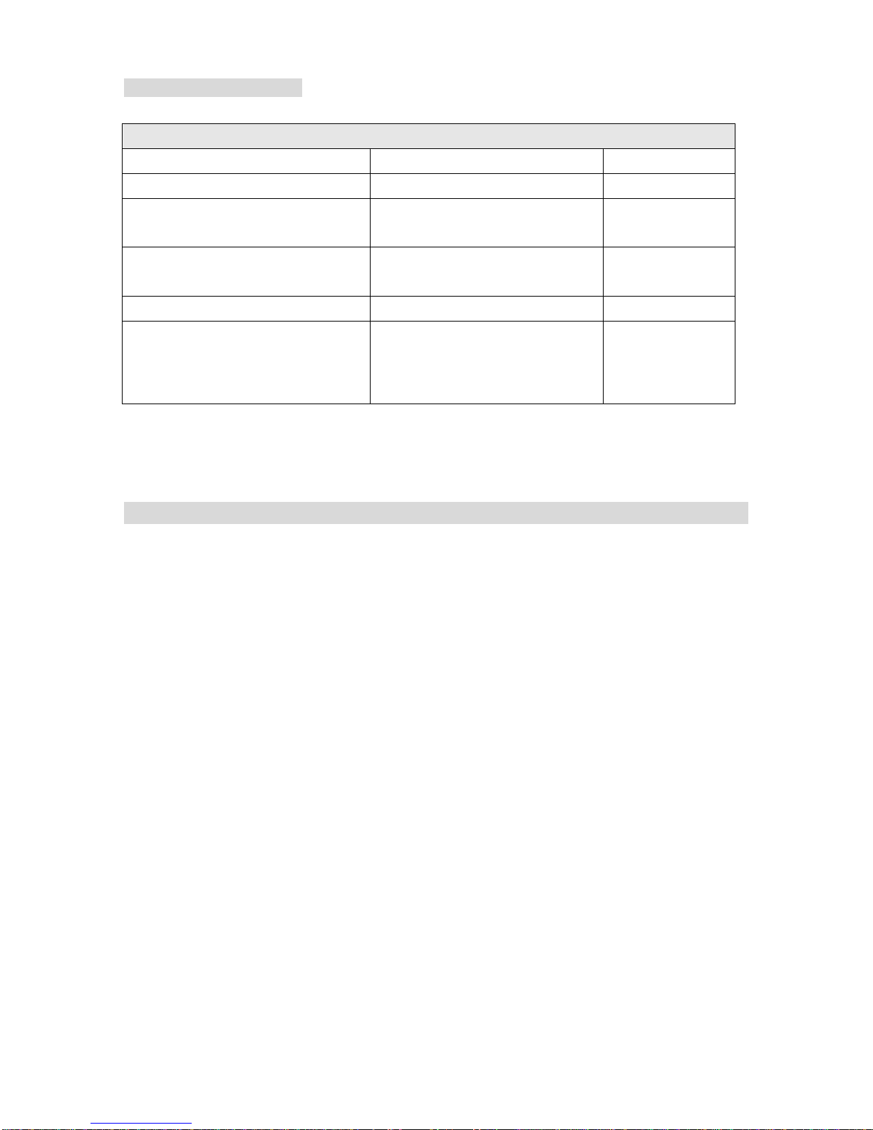
including 1000 cardholders with anti-pass-back function. Or connect with multi-door
networking controller to provide 15,000 cardholders with multi door anti-pass-back
access control. About networking of AR-721H series. Once the network communication
stop over 10 seconds on the RS-485 port. It will auto enter standalone control mode .
Notice:
The reader of AR-721HV2 owns the same functions as AR-721HV3 except for Calendar
& Time system supporting and 1,200 Transaction Buffer features.
Copyright © 2004 Soyal Technology Co. Ltd.
All Rights Reserved.
2. Features
Calendar & Time system supporting.
Providing proximity card flash edit mode
for easy & quick setting.
Two Sets of Auto-Open Zone Function.
Built-in opened door relay, alarm relay
and request to exit button input.
Up to 1,200 Transaction Buffer.
Master Card Range assignable.
Run as a standalone controller during
failure.
Support Auto-relock Function.
Universal serial port supported for LED display, printer, Lift controller, etc.
Intergrades any brand, any frequency of Wiegand reader with soyal or other access
control systems.
Keypad will be locked for 30 seconds while continuous error operation.
Press [*] + [#] to lock / unlock keypad immediately.
Built-in watchdog to prevent the system from halting.
Door unlock time setting, latched-on/latched-off or momentary 0.1-600 seconds.
Alarm function is available (temper, force entrance, door open too long, duress).
12 numeric keypad, 1 bicolor LED (green and red) and buzzer indicator.
2

3. Specification
Mode Description:
Access Mode A: Card only, Card + PIN, PIN + Code
Access Mode B: Card only, PWD only, Card + PWD
Access Mode C: Card Only, Card + PIN, PIN only
How to get the Mode Status
Step 1. Press
*
+ 1 2 3 4 5 6 + # enter the FUNCTION MENU
Step 2. You will hear the “Beep”sound from the
machine , as follows:
M4: Sound with 4 times
M6: Sound with 6 times
M8: Sound with 8 times
MODE M4 M6 M8
Card Holder 1024 65536 1024
Card Code 32 bits 16 bits 32 bits
Lift Control 32 * 32
Anti-Pass-back 1024 * 1024
Connect to 716EV2 Y * Y
PC Y * Y
Access Mode A B C
Transaction Buffer 1200 * 1200
How to change the Mode Status
Step 1. Press
# + 1 2 3 4 5 6 + # enter the FUNCTION MENU
Step 2. Editing Mode
M4:press 0 4 * 4 #and hearing
Beep Sound with 4 times
M6: press 0 4 * 6 #and hearing
Beep Sound with 6 times
M8: press 0 4 * 8 #and hearing
Beep Sound with 8 times
3

4.InstallationNotice
Drawing 1
Separateinstallation Reader Lock
Drawing 2
Lock
In the same pipe Reader
4

AR-721HV3 / 1356
1 RS-232: The distance between PC and converter
(AR-801CM) can not be more than 2 meters
2 RS-485: The distance between converter (AR-801CM) and
the farthest controller (or reader) can not be more than 300 meters.
3 Wiegand: The distance between RS-485 reader (or controller)
and Wiegand reader can not be more than within 3 to 5 meters.
4 Do not run AC power in the same pipe with communication wire(See drawing 2).
It should be separate installation (See drawing 1).
5 AR-721H locate inside the secure area for use as an exit
controller, the auxiliary reader locate exterior wall for use
as an entrance reader, but not directly behind AR-721H.
For best reading distance, offset the AR-721H and auxiliary
reader by about 50 cm above and 12 m below (suggestion value).
6 Normally, AR-721H will read a Card / Key Tag at up to 15
cm. However, when AR-721H or optional auxiliary reader is
mounted directly on a metal surface, the reading distance
decreases slightly. To reduce this effect, install wood or
plastic between the mounting surface and mounting plate,
this will restore most of the reading distance.
AR-721HV3 / 1356
7 Exit Switch input must be a dry contact, with no voltage present.
8 AR-721H can cover standard electrical boxes.
9 AR-721H does not supply power to operate electric strike or magnetic locks – a
separate supply is required. Refer to strike/magnetic lock manufactures instruction
s
If common power supply is used for both the AR-721H and electronic door lock, b
e
sure to install the diode which is provided with the AR-721H.
10 Alternatively, you can use any good 9-18 VDC supply that
provides at least 150mA. DC power should be clean and filtered
with no more than 1 VAC ripple (Peak to Peak). Do not run AC
power in the same cable with DC power to the AR-721H. While
it is always preferable to use a separate power supply for the
AR-721H and strike.
11 Run the following cables to the AR-721H location. Conduit is recommended to
reduce the effects of EMI/RFI and for physical protection of the wires.
5

We suggest that the customer use ”Shield Twisted Pair” and
avoid Star wiring for good communication when installation.
a. We suggest using the following cable in RS-485 communication.
b. Please use the following installation method, it is correct.
c. Don’t use the following installation method, it will cause
communication error.
801CM
OR
Controller
Controller
OR
Reader
801CM
OR
Controller
Controller
OR
Reader
6

The Difference of Cables
Cable Types and Distances
Wire Application Cable Type Description
From Power Supply 2-cond, 18-22 AWG n/a
From Locking Device and power
supply or gate operator 2-cond. See Mfr’s Specifications n/a
From external alarm system’s Doo
Monitor Switch (for shunting) 2-cond, 18-22 AWG 100 m
From Exit Button 2-cond, 18-22 AWG 100 m
From Optional Auxiliary Reader 2-cond unshielded 22 AWG,
plus a separate 4-cond,
shielded 22-24 AWG cable
50 cm - 12 m
5. Front Panel Indicators
1. In the programming mode, if no key or card entry is made within 30 seconds, it will
automatically exit the programming mode.
2. In the programming mode, LED light green and flash rapidly. It means that the
controller waits for entering. LED is red and flash rapidly, it means that the reader is
busy.
3. LED light green and one beep sound mean acknowledge, LED light red and two
beep sounds mean not acknowledge.
4. In card learn mode, after flash card, a green light and five beeps mean that same
card have existed in controller.
5. In anti-pass-back access mode, five beep sounds mean violates
access function. (For AR-721H4 and AR-721H8)
6. In arming state LED light green per 0.6 second. In disarming
state LED light green per 1.5 second, In alarm state LED light red per 0.4 second.
(For AR-721H4 and AR-721H8)
7. If three incorrect user code (or master code) are entered, keypad will be locked for
30 seconds.
8. Press button【0】+【#】to luck/unlock keypad.
9. Press button【*】+【#】for all cards entrance allowance.
10.Press button【#】to function as the Bell Output.
7

6. Access Mode
How to program
---2222 Duress Code (network)
---1111 Force On/Off Code (network)
---5678 Door Access User Code (network/standalone)
---1234 Arming and Disarming (network/standalone)
User can select one of the following access modes
AR-721HV3 /1356
Card only
User can access the door by flashing card on the unit.
Arming / Disarming: After flashing card ok, press 1 2 3 4 # Then the
unit will trigger the arming/disarming mode.
Card or PWD
User can access the door by just either flash card or entering 5 digit the user
number+ entering 4 digit user code + #
Arming/Disarming: After flashing card ok, press 1 2 3 4 # . Then the
unit will trigger the arming/disarming mode.
Arming/Disarming: entering 5 digit the user number+ entering 4 digit user code + # ,
then press 1 2 3 4 # . Then the unit will trigger the arming/disarming
mode.
Card or 4-digit User Code
User can access the door by just either flash card or entering 4 - digit user code.
Arming/Disarming: After flashing card ok, press 1 2 3 4 # . Then the
unit will trigger the arming/disarming mode.
Arming/Disarming: entering 4 digit user code, then press 1 2 3 4 # .
Then the unit will trigger the arming/disarming mode.
User can change user code any time
a. AR-721H connects with controller and PC, running 701 client and set user code
variable.
By user: After accessed ok, press 4-digit new user code twice and press #
By 701 client \ setting \ user card
b. Not connecting with PC
After accessed ok, press 4-digit new user code twice and press #
8

Duress function
This function could help users to send a message to the computer asking for help.
Only available in networking state, running 701 Server and setting 4 sets of Duress
code on PC. (Anyone of these 4 sets is workable.)
This function is not available for CARD ONLY and USER CODE ONLY (AR-721H8)
access.
Access Mode Command Format
Card Only Not available
Card + user code Flash card, then press Duress code & #
User code Only Not available
User no. + user code Press user no., then Duress code & #
Note: User can access door by duress code instead of user code
under card or user code access mode, but it will be shown ask for
help message in 701 Client \ Daily Transaction Record.
Force on/off Code (4 sets, 4 digits)
Only workable in networking system, running 701 Server and setting 4 sets of
Force code on PC. (Anyone of these 4 sets is workable.)
User could press related code to turn on / off its connected equipment, diagram as
below.
PC boad of Controller AR-716EV2 / AR-727E
COM
JP4
V12
CN5
DI.4
DI.2
DI.1
DI.3
COM
D10 D9
D11
K4
RELAY
K3
D12
RELAY
JP3
K1
K3
K4
K2 K2
RELAYRELAY
K1
Relay Code
K1 16
K2 17
K3 18
K4 19
9

After access OK, press following order to turn on / off its connected equipment.
Access mode ON/Off Order
ON Flashing card+Force code+Code+0+#
Card only Off Flashing card+Force code+Code+1+#
ON Flashing card+User code +Force code+Code+
0+#
Card + user
code Off Flashing card+User code +Force code+Code+
1+#
ON User no. +User code +Force code+Code+0+
#
User no. +
user code
(Mode 4) Off User no. +User code +Force code+Code+1+
#
ON User code +Force code+Code+0+#
User code
only
(Mode 8) Off User code +Force code+Code+1+#
This function can be connected with force control television, air conditioning, audio,
etc. by Relay-1, 2, 3, 4 on the multi-door networking controller.
To avoid the conflict of the use of each controller relay, it is user responsibility to
define each controller relay for one purpose use only.
10

7. Function Default Value
Before installing, complete the Parameters setting by calculating
each controller value according to their designated functions.
[Command 20] is used to enter [Designated Functions Setting Table]
value. The default factory setting value is 016.
7.1 For AR-721HV3/ 1356
Designated Functions Setting Table
Functions Optional Bit Value Remark
Recording every entry/exit on
Time Attendance Report 0:YES
*
1:NO 0 001 network
Auto Re-Lock 0:disable
*
1:enable 1 002
Auto Open/Auto Disarming 0:disable
*
1:enable 2 004 network
Door Exit Release
(Push Button) 0:disable 1:enable
*
4 016
Master Reader /Network 0:minor
*
1:major 5 032 network
Entry / Exit door 0:exit door
*
1:entry door 6 064
Anti-pass-back door 0:disable
*
1:enable 7 128
Listed above with [
*
] markings are the factory setting. Multiply the
optional functions number [1] by its value and add them up.
Note that AR-721H7 has no Anti-pass-back door function.
7.2 For AR-721H6
Designated Functions Setting Table
Functions Optional Bit Value Remark
Auto Re-Lock 0:disable
*
1:enable 1 002
Door Exit Release 0:disable 1:enable
*
4 016
11

8.Wiring
Table 1 - Connector P1 Color Coding
Wire Application Wire Color Description
1 Blue White (N.O.)DC24V1Amp
2 Purple White (N.C.)DC24V1Amp
Door Relay
3 White (COM)DC24V1Amp
Door Sensor 4 Orange Negative Trigger Input
Exit Switch 5 Purple Negative Trigger Input
Alarm Output 6 Grey Transistor Output
(Open Collector Active Low )
7 Thick Red DC Power 12V
Power
8 Thick Black DC Power 0V
Table 2 - Connector P2 Color Coding ( Wiegand Read Head )
Wire Application Wire Color Description
1 Thin Blue Wiegand DAT:1 Input
Wiegand
2 Thin Green Wiegand DAT:0 Input
Beeper 3 Pink Beeper Output 5V/100mA, Low
4 Brown LED Green Output 5V/20mA, Max
LED
5 Yellow LED Red Output 5V/20mA, Max
Table 3 - Connector P3 Color Coding (Tamper Switch )
Wire Application Wire Color Description
1 Red N.C.
2 Orange COM
Tamper Switch
3 Yellow N.O.
Table 4 - Connector P4 Color Coding
Wire Application Wire Color Description
1 Thick Green RS-485(B-)
Networking
Module 2 Thick Blue RS-485(A+)
12

9.Installationdiagram
9.1 Magnetic lock
Purple(Exit Switch)
The installation of 721H and magnetic lock
+12VDC
AR-721H Standalone Controller
Lock(+12VDC )
Magnettic Lock
Lock( -GND )
-GND
721H
CN4
RELAY
7AC2
CN2
CN1
White( COM. )
Purple White( NC. )
P 1
CN1
Power Supply
12VDC 2A
COM.
-GND
CN3
SOYAL
12VDC 500mA
Power Supply
Red( +12VDC )
Black( - GND )
+12VDC
Push Button
DOOR EXIT
NO.
13

9.2 Electric bolt lock
The installation of 721H and electric bolt lock
Electric Bolt Lock
721H
CN4CN2
7AC2
Lock(+12VDC )
Lock( -GND ) Power Supply
12VDC 2A
+12VDC
-GND
CN1
P1
RELAY
CN1
Blue White( NO. )
White( COM. )
Power Supply
12VDC 500mA
CN3
SOYAL
-GND
Black( - GND )
Red( +12VDC )
+12VDC
Purple
DOOR EXIT
Push Button
NO.
COM.
14

9.3 Electric strike
+12VDC
The installation of 721H and electric strike
AR-721H Standalone Controller
Electric Strike
12VDC 500mA
Power Supply
+12VDC
-GND
Purple(Exit Switch)
Push Button
DOOR EXIT
NO.
Lock(+12VDC )
Install
Diode
721H
7AC2
CN4
RELAY
-GND
Lock( -GND )
CN1
P 1
Blue White( NO. )
White( COM. )
Power Supply
12VDC 2A
COM.
CN2
CN1
CN3
SOYAL
Black(- GND )
Red( +12VDC )
15

9.4 Magnetic door contacts and alarm system
CN2CN3
SOYAL
Power Supply
12VDC 500mA
Magnetic Door Contacts(COM.)
Black( - GND )
Red( +12VDC )
CN1
Gray( ALM. )
COM.
ALM.
+12VDC
Black( - GND )
Red( +12VDC )
N.O.
N.C.
Alarm System
-GND
+12VDC
magnetic door contacts and alarm system
AR-721H Standalone Controller
The installation of 721H
Megnetic
DoorContacts
CN4
721H
7AC2
Magnetic Door Contacts( NC. )
Magnetic Door Contacts( COM. )
12VDC 2A
Power Supply
RELAY
Orange(Door Sensor)
CN1
P 1
+12VDC
- GND
16

9.5 Wiegand reader
9.5.1 AR-721U
-GND
+12VDC
Power Supply
12VDC 500mA
The installation of 721H and auxiliary reader 721U
CN3
SOYAL
Red
Black
A
CN2
P2
1
7AC2
CN2 CN4
721H
CN1
P1
CN1 RELAY
Yellow
Brown
Pink
Green
Color
Blue
2
4
5
3
1
Pin
A
Purple
Yellow
Brown
Green
Blue
Pin
B
AR-721U
Green LED
Red LED
Beeper input
DAT:0
DAT:1
Function
Black
Red
B
17

9.5.2 AR-661U
The installation of 721H and auxiliary reader 661U
12VDC 500mA
Power Supply
+12VDC
-GND
Black
CN1 RELAY
CN1
P1
Blue
Pin
Green
Blue
Color
Green
2
Pin
1
ABFunction
DAT:0
DAT:1
Red
B
Red
Black
~
1
SOYAL
CN3 CN2
P2
A
CN2
CN4
721H
7AC2
18

9.5.3 AR-737U
Red+12VDC
BPinPin Color
AFunction
SOYAL
The installation of 721H and auxiliary reader 737U
CN2
P2
A
B
CN4
AR-737U
1
CN2
Red
CN3
-GND
Black
P1
CN1
RELAY
7AC2
CN1
Black
Green
2Green BlueBlue
1
Brown
PurplePink
4
3Brown
Yellow
5Yellow
Power Supply
DAT:0
DAT:1
12VDC 500mA
Green LED
Red LED
Beeper input
19
Other manuals for AR-721HV3
1
This manual suits for next models
1
Table of contents
Other Soyal Door Lock manuals
Popular Door Lock manuals by other brands

I.H.T
I.H.T IDL707 quick start guide

Richelieu
Richelieu 87D2S24 Series installation instructions

INSYS
INSYS Wittkopp Cawi CombiStar 7250 simplex user manual

Assa Abloy
Assa Abloy Corbin Russwin MP9800 Series installation instructions

Assa Abloy
Assa Abloy Lockwood 8653 installation instructions

Yale
Yale EC800 user manual

Assa Abloy
Assa Abloy Sargent IN220 installation instructions

SECO-LARM
SECO-LARM SD-997B-GBQ installation manual

Blusafe
Blusafe Breeze Fitting instructions

SOREX
SOREX SMART Quick starting guide

Best
Best IDH Max 1300 installation instructions

Security People
Security People Digilock installation instructions