68
7
PUSH ALL EXCESS WIRE LENGTHS DOWN THROUGH THE OPENING
AT THE TOP OF THE INSIDE LOWER HOUSING.
1. Attach the battery cover with two finished #8 screws. Battery cover has a
lip which engages the lower inside housing, it is important that this lip be
seated properly to insure correct alignment.
1. Slide the inside lower housing over the lever tube until it has passed over the
lever catch. (Be sure wires are not pinched.)
2. Fasten with two brass #8 screws. Once secure, fasten the finished #8 screw
at the bottom.
Insert 4 AA batteries into battery holder. (Note polarity.)
Note:
All
wire
pairs
are
color
coded
to
connect
with
like
colored
pairs.
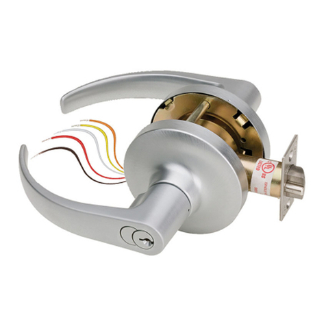
1. Connect the grey/red wires from the raceway to the grey/red wires from the lever tube.
The two remaining pairs are only for the optional
sensor-array package, as well
as the “reset lock” function. (See page v of the programming guide.)
2. Connect the red/black wires from the raceway to the red/black wires from the battery pack.
3. Place the battery holder over the center grooved stud.Note: The fork, located on the
bottom of the battery holder will clear the lower inside housing.
4. When properly aligned, push down on the battery holder assembly, engaging the upper
part of the hole into the groove of the center stud. This will connect the lower fork with
the center post, giving a very secure fit.
NOTE:
USE
ONLY
ALKALINE
BATTERIES,
DUE
TO
PREDETERMINED POWER SETTINGS IN THE LOCK.
M:\INS\INST-E72.qxd REV B 0202 Page 2
5
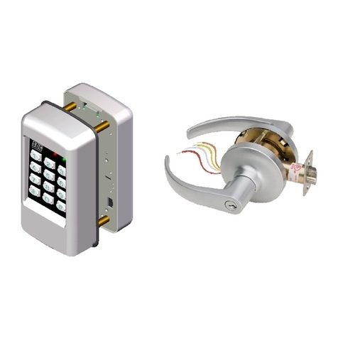
1. Feed the cable assembly with connectors through the backplate and raceway nut.
2. While holding the interior backplate in position, loosely install the two thru-bolts.
3. Tighten the raceway nut on the raceway tube that passes through the door using a
crescent or 7/8” socket wrench .
When this connection is tight, secure the thru-bolts.
4. Tear cable wrap to separate wires.
Remove
screw
from
Battery
Cover
to
access
backplate.
