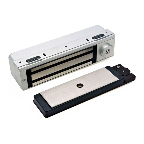
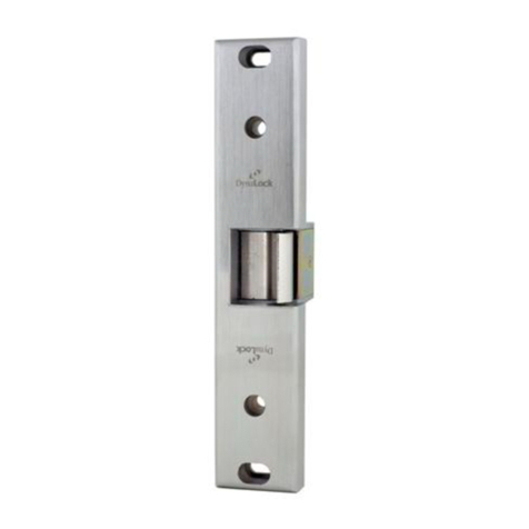
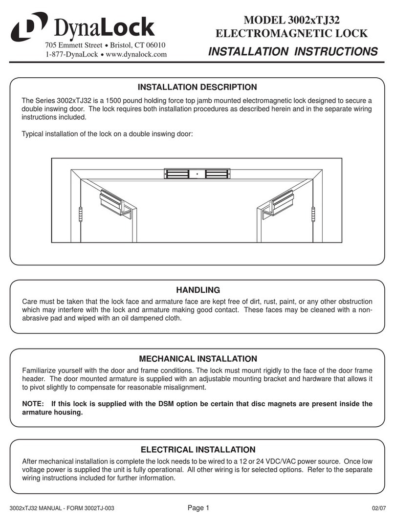
DynaLock 2280 User manual

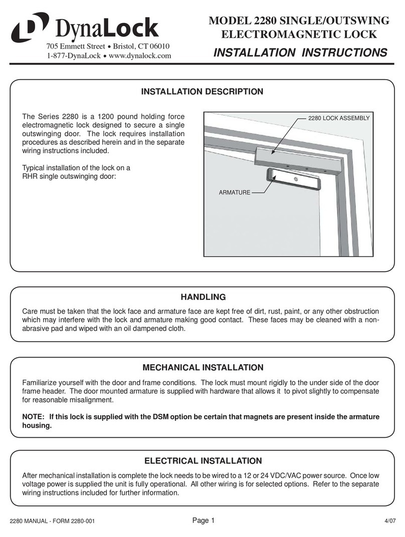
The illustrations below depict typical installations of the Model #2511 Lock on single-outswing doors. The lock
assembly must be surface mounted to the underside of the frame header with the armature affixed to the inside
faceofthedoorasshown.
DynaLock Corp.
Electric Security Hardware
705 Emmett Street P.O. Box 9470 Forestville, CT 06011-9470 Phone (860)582-4761 Fax (860)585-0338
MOUNTING INSTRUCTIONS
SERIES 2511 ELECTROMAGNETIC LOCK
FOR A SINGLE OUTSWING DOOR
PLEASE READ BEFORE INSTALLATION
.
Familiarize yourself with the door and frame conditions prior to installation. The lock must rigidly mount to the
underside of the frame header. The armature is designed to pivot slightly to compensate for reasonable
misalignment.
Armature mounting hardware is supplied for a standard 1-3/4" thick door. For thicker doors order the following
specialarmaturehardwarekits:
Part#300687for2"thickdoors.
Part#300688for2-1/4"thickdoors.
HANDLING MAINTENANCE
The Electromagnetic lock and armature are
ruggedly constructed and designed to provide
years of trouble-free service. Care must be taken
during installation and use to keep the lock face
and armature face free from dirt, rust, burrs, paint,
or any other obstruction which may interfere with
thelockandarmaturemakinggoodcontact.
The lock assembly and door armature have been
plated for maximum corrosion resistance. To
ensure peak performance clean the lock and
armature faces with a mild detergent and a clean,
softcloth,thenapplyalightcoatofWD40toprotect
these surfaces. This need only be done when dirt
build-upisnoticed.
page 1
GENERAL MOUNTING INFORMATION
LHRB DOOR RHRB DOOR
LOCK
ASSEMBLY
ARMATURE
GLASS AND ALUMINUM
OR
HOLLOW METAL DOOR SOLID CORE DOOR REINFORCED DOOR
Drill an 11/32" diameter hole
through door. From sex nut
side only enlarge the 11/32"
holeto21/32"diameter.
Drill an 11/32" diameter hole
through door. From sex nut
side only drill 1/2" diameter
holeto1"depth.
Drill an 17/64" diameter hole
andtapfor5/16"-18thread.
ARMATURE
STEEL WASHER
ARMATURE
SCREW
RUBBER
WASHER
ARMATURE
SPACER
DOOR
SPACER
SEX
NUT
21/32"
STEEL WASHER
ARMATURE
ARMATURE
SCREW
ARMATURE
SPACER
RUBBER
WASHER
1/2"
1"
STEEL WASHER
ARMATURE
ARMATURE
SCREW
ARMATURE
SPACER
RUBBER
WASHER
5/16"-18 THREAD
page 2
MOUNTING PREPARATION
SURVEY THE INSTALLATION
PREPARETHEFRAME FORMOUNTINGTHE LOCKASSEMBLY
PREPARETHEDOORFORARMATUREMOUNTING
Inspect the door frame and determine if an angle bracket or filler plate will be required for installation. The lock will
requirea1-3/4"wideheaderstopforasuitablemountingsurface.
Determinethehandofthedoor-LHRBorRHRBandlookatthetemplateedgeforproperpositioningof thetemplate.
A. Foldthetemplateonthedottedlinetoforma90degreeangle.
B. Withthedoorintheclosedandlatchedpositon,placethetemplateagainsttheheaderanddoor
with one edge of the templateagainsttheverticallockjambandtapeinplace.
C. Transferallholelocationstoboththedoorandheaderwithacenterpunch.
D. Removethetemplatefromthedoor.
From the three illustrations below, select the one that resembles your door type and follow the instructions for drilling
the armature mounting screw hole. Drill two (2) 1/4" dia. holes 9/16" deep at the anti-spin pin locations ( See
Template).
1.
2.
3.
1 3/4"
MIN.
NORMAL MOUNTING
*FILLER PLATE REQUIRED
*ANGLE BRACKET REQUIRED
*These items are available from DynaLock

MOUNT THE ARMATURE TO THE DOOR
Failuretoproperlysecurethearmaturetothedoor couldresultinseriousinjuryorpossible security breach.
PREPARETHEHEADERFORLOCKMOUNTING
MOUNTTHELOCKTOTHEHEADER
CHECKLOCKANDARMATUREFORPROPERALIGNMENT
COMPLETION
The mechanical installation is now complete. Refer to separate wiring instructions for electrical hook-up
information.
Locatethetwo3/16"dia.anti-spin pins fromthehardwarekit. Placethe armature face-downonasoftsurface( i.e. the
shippingcarton)anddrive theanti-spinpinsintothe holesprovided. RefertoNote#3illustrationsto select the correct
mounting hardware and mount the armature. Firmly tighten the armature mounting screw with a 3/16" hex wrench.
RefertotheTemplateanddrill four1./8"dia.mountingholesandone9/16"diameterwiringholewhereshown.
Remove the Access and End Covers from the lock assembly (see Exploded View - page 4). Using the four #10 x 1"
phillips flatheadself-tappingscrewsprovidedsecurethelockassemblytotheheader.Firmlytightenthescrewswitha
#2 phillips head screw driver. Locate the four anti-tamper plugs and install over the mounting screw holes with a soft
mallet.ReplacetheAccessandEndCovers.
Closeandlatchthe door. Verifythatthelockface andarmaturearemakingfull contact overtheentirearmaturelength.
Thearmaturemustbealignedtocoverthefullactivefaceofthelock,representedbythethreeparallelbarsvisiblefrom
thefront.Shouldthearmature offsetholdingforcewillbereducedsignificantly.Makeanycorrectionsasnecessary.be
4.
5.
6.
LOCK ASSEMBLY
MOUNTING SCREW (TYP.)
ANTI-TAMPER PLUG (TYP.)
7.
8.
page 3
ARMATURE AND
LOCK FACE MUST
MAKE FULL CONTACT
MAGLOCK
HEADER
SHOULD BE PARALLEL
VIEW LOOKING
UP AT HEADER

2511 BILL OF MATERIAL TOOLS REQUIRED
1. Magnet Assembly
2. Armature
3. Access Cover Assy.
4. End Cover
5. Mounting Screw
6. Anti-tamper Plug
7. Armature Spacer
8. Rubber Washer
9. Anti-spin Pin
10. Steel Washer
11. Armature Bolt
12. Door Spacer
13. Sex Nut
Consult Factory
#300141
Consult Factory
#300165
DESCRIPTION PART NUMBER
1 - Electric Drill
1 - #2 Phillips Head Screw Driver
1 - Soft-faced Mallet
1 - 3/16" Hex Wrench
1 - 11/32" Drill Bit
1 - 21/32" Drill Bit
1 - 9/16" Drill Bit
1 - 1/8" Drill Bit
1 - 17/64" Drill Bit
1 - 1/4" Drill Bit
1 - Hammer
1 - Center Punch
Pencil & Tape
1 - Mounting Instructions
1 - Wiring Instructions
1 - Electromagnetic Lock
1 - Hardware Kit consisting of:
4 - #10 x 1" Phillips Flat Head
self-tapping screws
4 - Anti-tamper Plugs
1 - 1/4" long Armature Spacer
1 - 1/8" thick Rubber Washer
1 - 1/16" thick Steel Washer
2 - 3/16" x 3/4" long Anti-spin Pins
1 - Template
1 - Armature Bolt assembly
consisting of:
1 - 5/16-18 x 2" Hex flat
head machine screw.
1 - 5/16-18 Sex Nut
1 - 1-11/16" long Door
Spacer
1 - Armature
page 4
2511
Hardware Kit
Part #300762
EXPLODED VIEW
012500
2511manual.CDR
1
1-1/4"
1-3/4"
10-1/2"
6
54
3
7
8
10
11
2
9
6-1/2"
1-1/2"
3/8"
12 13

Page 1
2500/2280 WIRING
SERIES 2500 & 2280
ELECTROMAGNETIC LOCK
WIRING INSTRUCTIONS
1/07
DynaLock
705 Emmett Street Bristol, CT 06010
1-877-DynaLock www.dynalock.com
OVERVIEW
Familiarize yourself with the illustrations and instructions on this data sheet before attempting to wire this unit.
The circuit board illustrations show a lock with every possible option - your lock may not have certain options.
CIRCUIT BOARD DESCRIPTION & COMPONENT LOCATION
COIL CONNECTION AND VOLTAGE SELECTION
WHT
BLK
WHT
BLK
RED
WHT
GRN
COIL CONNECTOR
4-PIN PLUG
DYNASTAT CONNECTOR
3-PIN PLUG
POWER INPUT
12/24 VDC/VAC
NO POLARITY
VOLTAGE SELECTION
(SEE BELOW)
OPTIONAL
DOOR
STATUS
(DSM)
OPTIONAL
DYNASTAT
(DYN)
REMOVEABLE JUMPERS
VOLTAGE SELECTION
SET FOR 12 VOLTS SET FOR 24 VOLTS
REMOVEABLE COIL
AND DYNASTAT
CONNECTORS
• THE COILAND DYNASTAT CONNECTORSARE POLARIZED. MAKE SURE
ALL PINS ARE CONNECTED.
• ADJUST THE JUMPERS AS SHOWN BELOW TO MATCH THE INPUT
VOLTAGE TO THE LOCK.
ALL CONTACTS
SHOWN IN UNSECURE
/ DOOR OPEN STATE
WHT
BLU
BLK
RED
GRN
BRN
BLU
2280 2500
2280 2500

Page 2
2500/2280 WIRING
SERIES 2500 & 2280
ELECTROMAGNETIC LOCK
WIRING INSTRUCTIONS
1/07
DynaLock
705 Emmett Street Bristol, CT 06010
1-877-DynaLock www.dynalock.com
NC
NO
C
DSM
NC
NO
C
DYN
DYNALOCK CORP.
INPUT FROM
INDICATOR POWER
SOURCE
DOOR OPEN
DOOR CLOSED
DOOR STATUS (DSM)
OPTION
DOOR POSITION SWITCH
ANTI-TAMPER (ATS)
OPTION -
2500 ONLY
1
2
12/24
VDC / VAC
INPUT
POWER INPUT
12/24 VDC/VAC
NORMALLY CLOSED STATION
CONTROL(S), I.E. PUSHBUTTON,
KEYSWITCH, ETC.
WIRE MULTIPLE CONTROLS IN
SERIES AS SHOWN.
CURRENT DRAW:
2280 0.68A @ 12VDC / 0.35A @ 24VDC
2500 0.50A @ 12VDC / 0.25A @ 24VDC
(SHOWN PER COIL)
NC
NO
C
DSM
NC
NO
C
DYN
DYNALOCK CORP. DOOR UNSECURE
DOOR SECURE
INPUT FROM
INDICATOR POWER
SOURCE
DYNASTAT (DYN)
OPTION
LOCK STATUS/BOND SENSOR
DRY CONTACT RATING:
0.25A @ 24VDC
NOTE:
INDICATORS NOT INCLUDED
DRY CONTACT RATING:
0.25A @ 24VDC
NOTE:
INDICATORS NOT INCLUDED
DRY CONTACT RATING: 0.25A @ 24VDC
ANTI-TAMPER OPTION INDICATES REMOVAL OF
ACCESS COVER. THIS OPTIONAL SWITCH WOULD
BE LOCATED INSIDE THE LOCK HOUSING. SHOWN
WITH COVER ON. WHITE = COMMON
RED = NORMALLY OPEN
GREEN = NORMALLY CLOSED

Page 3
2500/2280 WIRING
SERIES 2500 & 2280
ELECTROMAGNETIC LOCK
WIRING INSTRUCTIONS
1/07
DynaLock
705 Emmett Street Bristol, CT 06010
1-877-DynaLock www.dynalock.com
NC
C
NO
RESISTOR
LED
RED
BLACK
GREEN
The Bi-Color LED is used in conjunction with the Dynastat (DYN) option to display lock status in two colors - red or green
and is pre-configured to operate on 24VDC. For 12VDC operation remove the outer resistor from the black wire. Connect
the LED to the DYN as shown below.
LED OPTION
LOCK - DYN
TIME DELAY (TD) MODULE WIRING
Optional Model 7080 inline time delay module provides adjustable time delayed relocking. This is a field installed
device and wired per the following wiring diagram.
REMOVE FOR 12VDC OPERATION
LED
Red= Door Locked
Green= Door Unlocked
-
+
TD Module
Trim Pot
Rotate trim pot clockwise
to increase time delay.
Range = 0-60 sec.
Time Delay Adjustment
NORMALLY-CLOSED
MOMENTARY
STATION CONTROL
POWER
SUPPLY
RED
BLUE
GREEN
WHITE
BLACK
()
()
LOCK
(NOT USED)
TD OPTION
TIME DELAY
MODULE
1
2
+
-
7080
TIME DELAY
MODULE

Page 4
2500/2280 WIRING
SERIES 2500 & 2280
ELECTROMAGNETIC LOCK
WIRING INSTRUCTIONS
1/07
DynaLock
705 Emmett Street Bristol, CT 06010
1-877-DynaLock www.dynalock.com
OPERATING VOLTAGES: 12 or 24 VDC/VAC Field Selectable
CURRENT DRAW: 2280 0.68A @ 12VDC / 0.35A @ 24VDC
2500 0.50A @ 12VDC / 0.25A @ 24VDC
(SHOWN PER COIL)
SURGE SUPPRESSION: Built-in
COIL RESISTANCE: 2280 34.1 Ohms (+-10%) Black-White / Red-Blue
2500 53.8 Ohms (+-10%) Black-Black / White-White
GENERAL SPECIFICATIONS
PLEASE DELIVER THIS MANUAL
TO THE END-USER UPON COMPLETION
OF THE INSTALLATION
FOR PRODUCT SUPPORT AND PARTS
ORDERING INFORMATION CONTACT:
DynaLock Corp.
705 Emmett Street
Bristol, CT 06010
Bus: (877) DYNALOCK, Toll-Free USA
(860) 582-4761
Fax: (860) 585-0338
DYNALOCK ON THE INTERNET:
E-mail: [email protected]
Website: www.dynalock.com
Other manuals for 2280
1
This manual suits for next models
2
Table of contents
Other DynaLock Door Lock manuals

DynaLock
DynaLock 2280-TJ80 User manual

DynaLock
DynaLock 2280 User manual

DynaLock
DynaLock 3101C User manual

DynaLock
DynaLock 3101B User manual

DynaLock
DynaLock 3001 TJ31 Series User manual

DynaLock
DynaLock 1661 User manual

DynaLock
DynaLock 1661 Series User manual

DynaLock
DynaLock 2282-TJ82 User manual

DynaLock
DynaLock 3002 TJ32 Series User manual