A
A
B
C
B
B
C
A
B
C
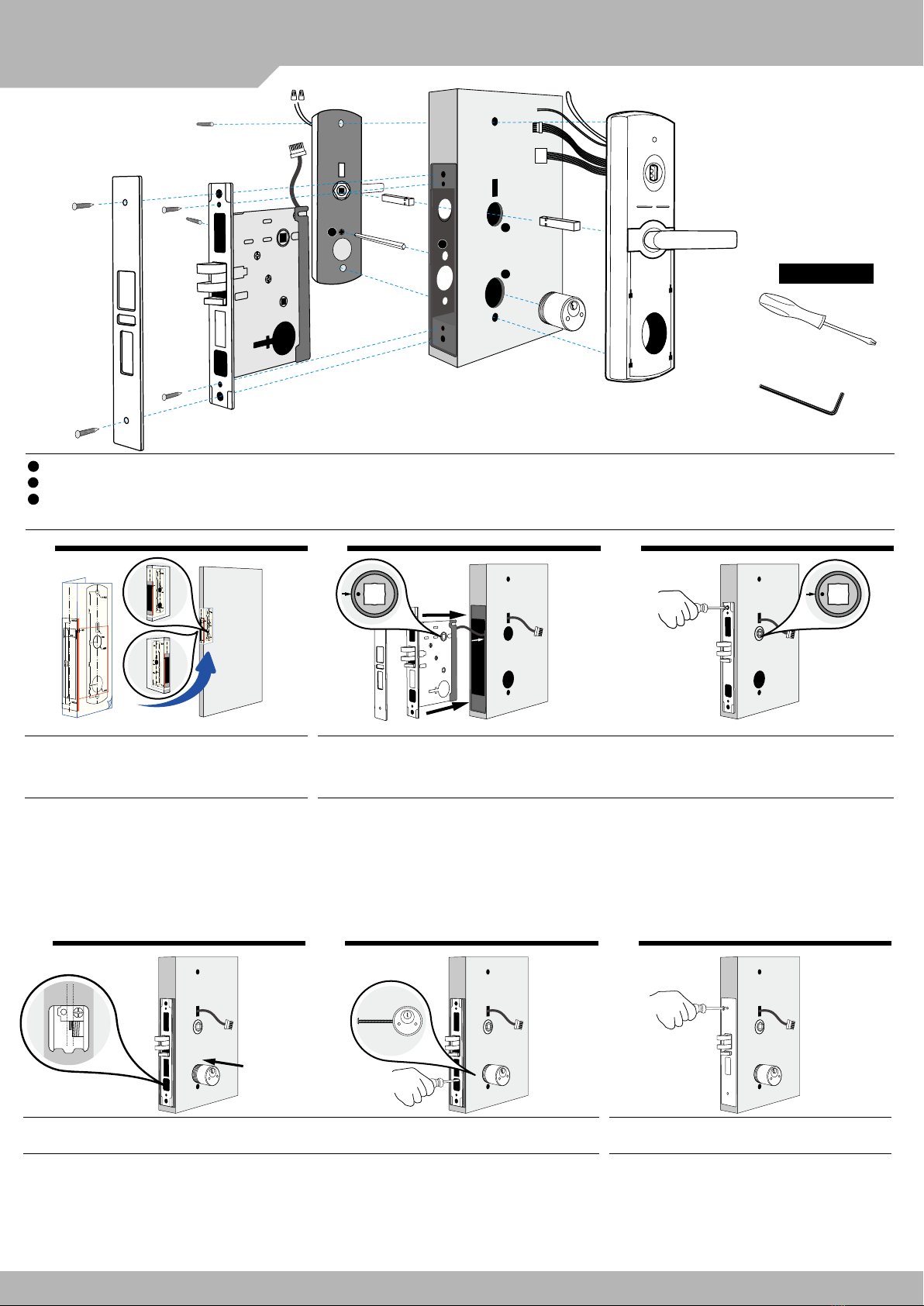
Handle hole / 把手孔
Deadbolt knob hole / 暗鎖孔
Cylinder hole / 鎖頭孔
5. Connector of Door contect / 門位磁簧線
6. Front panel / 外門座
7. Spindle of handle / 把手方柱
8. Mortise/ 鎖匣
9. Mortise plate / 鎖匣面板
10. Spindle of Knob / 暗鎖方柱
11. Back panel / 內門座
2. Connector of reader / 讀頭通訊線
3. Connector of mortise / 鎖匣排線
4. Power connector / 電源線
5. Connector of Door contect / 門位磁簧線
1.
7.
7.
2.
4.
5.
3.
6.
8.
10.
9.
11.
3.
Cross-Head screw driver /
十字起子
Inner hexagon screw driver /
內六角板手
Tools / 工具
13. 14. 15.
安裝內外面板 安裝舌孔內置盒及鎖舌擋板
(1)單機型需先安裝電池後再安裝內上面板(滑蓋式)。
Stand-alone: Install battery before the upper cover of
back panel.
(2)安裝內下面板(卡扣式:面板上端先插入把手腰帶扣環的
下側,再將面板下端向金屬座平壓扣緊。)
Install the lower cover of back panel as above picture
shown.
(3)安裝外下面板(滑蓋式)
Install the lower cover of front panel.
(1)建議鎖舌孔需開挖到能安置舌孔內置盒的程度,並注意擋 板位置及方向。
Make sure position and right hole direction for Strike box.
1. 2. 3.
115.87
20*10
115.87
20*10
115.87
20*10
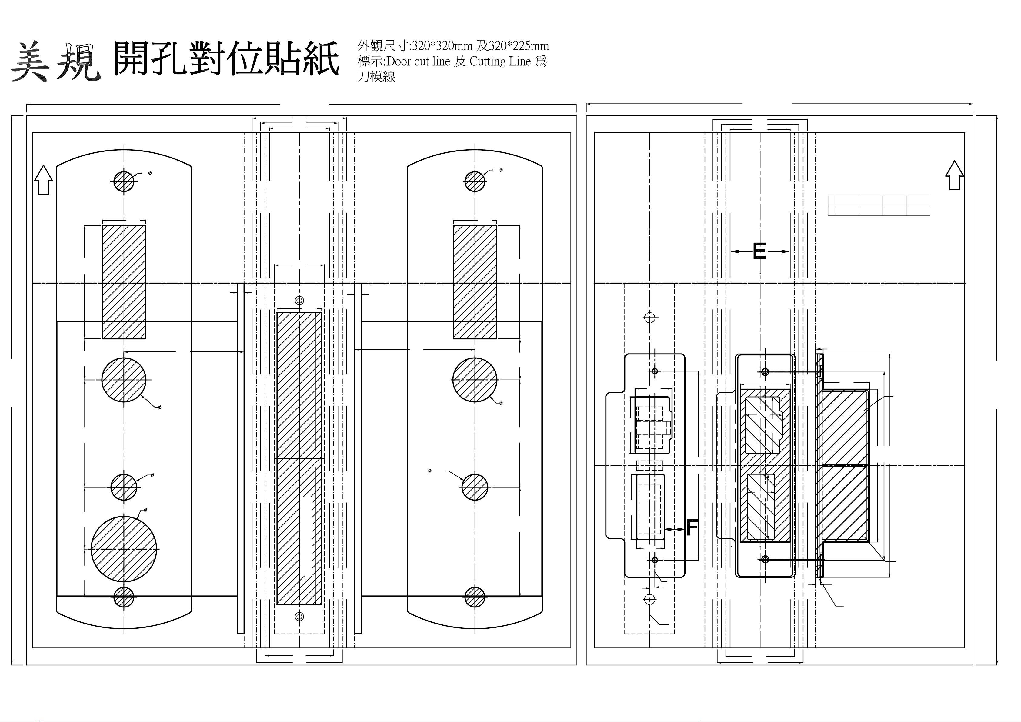
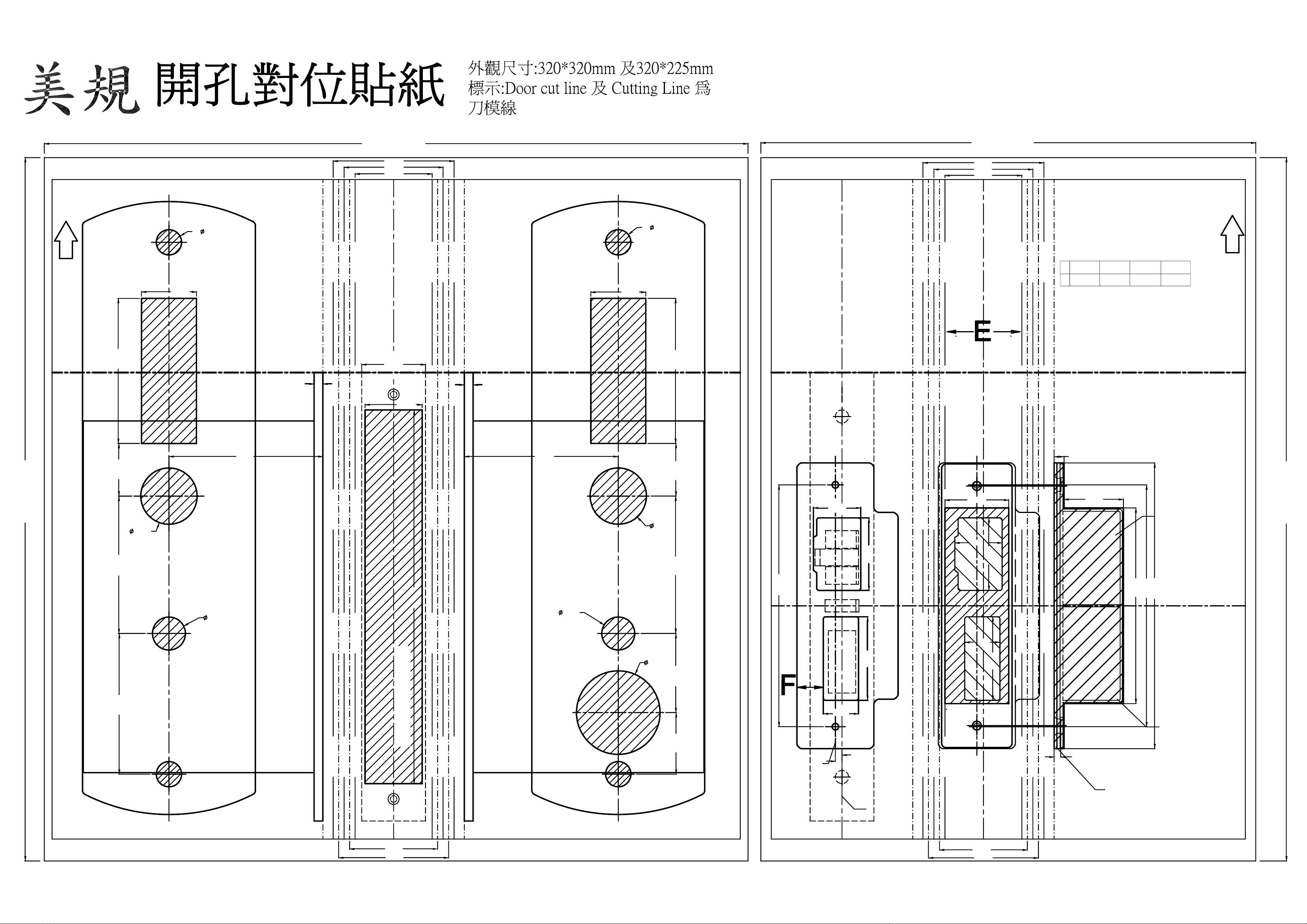
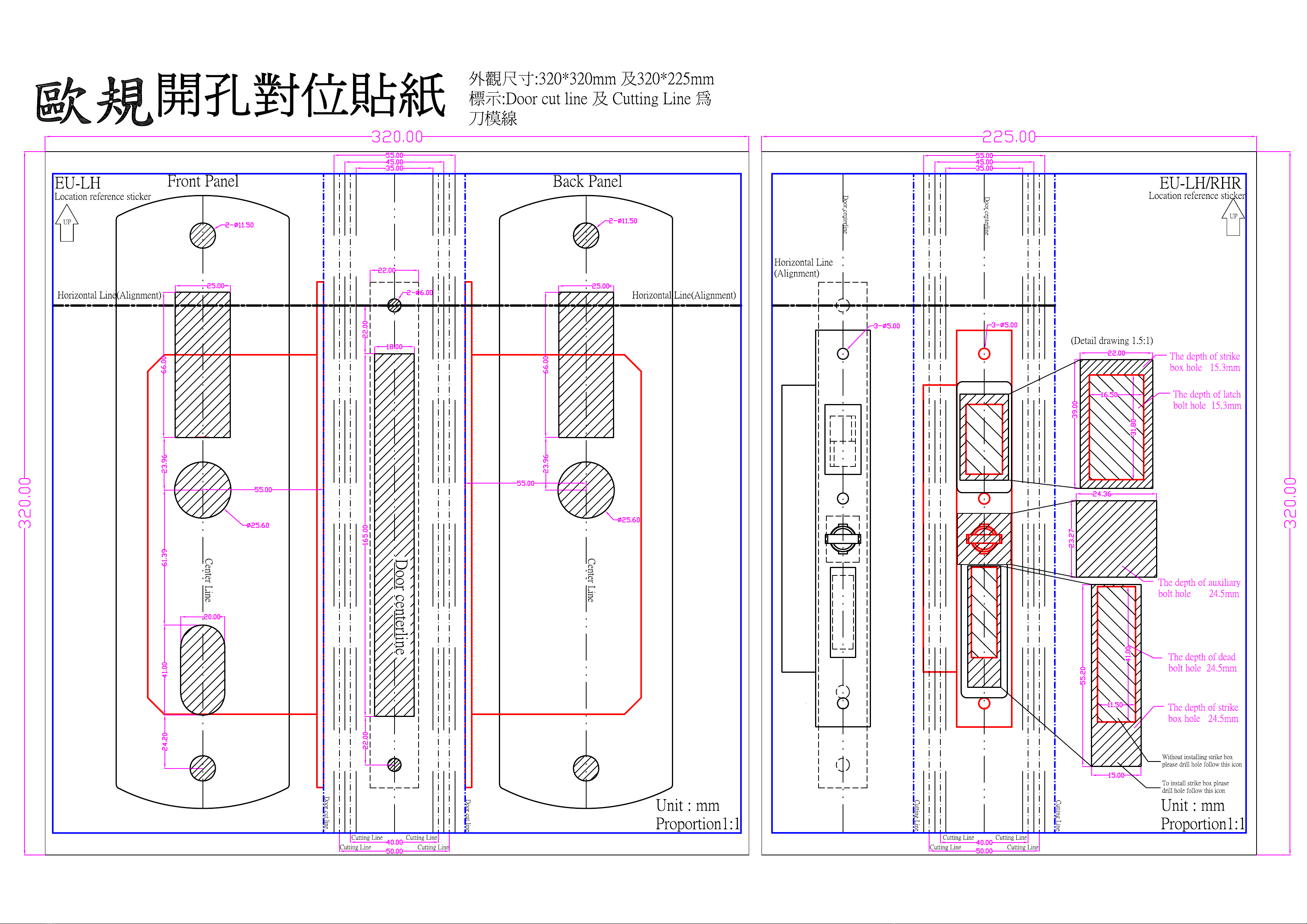
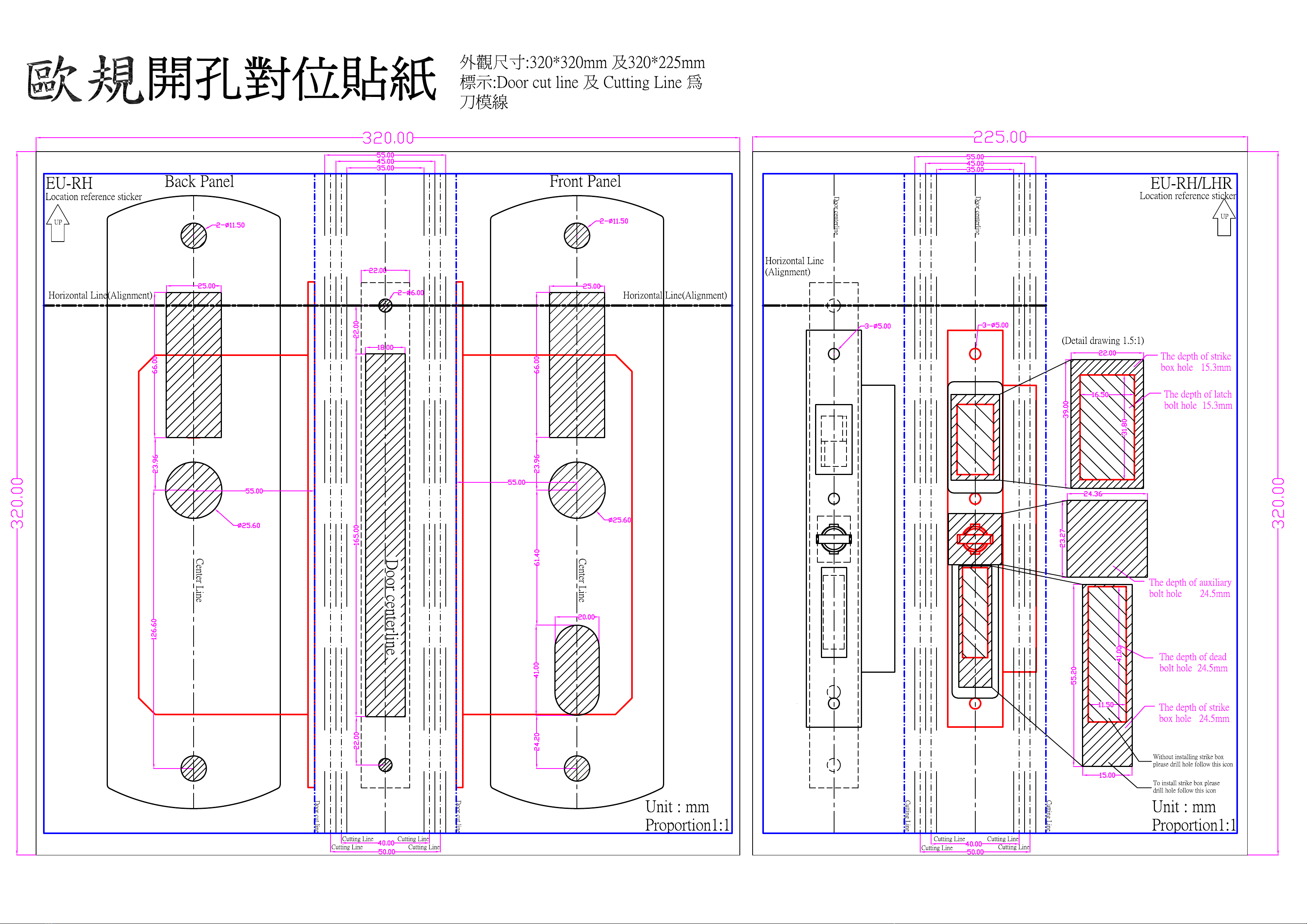
Paste hole-sticker on the door properly and make
cuts depending on hole-stickers dimension.
Install cylinder into mortise , use the screw to fix cylinder properly Installation Mortise plate
Take away mortise plate , embed mortise into door frame and fix it with screws properly.
Insert the spindle of handle separately into the
handle hole of mortise.
Installation front and back panel. Installation Strike and Strike box
The spindle of handle insert deadbolt knob hole,
front and back panel clamped and fixed on the
door with inner hexagon screw properly.
Connect the front panel connector to mortise.
Use tools "Plastic PICK" to guide rubber pad to fit
with front and back panel and then fixed them
together with the screws.
Connect power connector to
Battery-pack.
connect AR-321DAX1 to connector of
reader and install door contact if need.
Networking
mode
將孔位貼紙貼在欲安裝飯店鎖的位置,依孔位貼
紙圖示在門及門框上開孔挖槽
Paste hole-sticker on the doorframe properly and
make cuts depending on hole-stickers dimension.
將孔位貼紙貼在欲安裝飯店鎖的位置,依孔位貼
紙圖示在門框上開孔挖槽
卸下鎖匣修飾板,將鎖匣埋入門扇並以螺絲固定
(1)注意開孔位置,門內側暗鎖孔為盲孔(僅門內側到鎖匣處開孔)
Only make "deadbolt knob hole" from inner door to
mortise, don't cross to outer door.
(2)舌孔固定板定位需準確,並注意開孔方向,可於飯店鎖鎖
舌位置確定後再開孔。
make sure accurate position & right hole direction of
striker plate; before making cuts, latch bolt position can
be made firstly.
(3)連線型需另外再開走線孔。
Networking mode : Additional hinge cuts is required for
PC connection.
(1)埋入鎖匣前需確認鎖匣方向孔位皆正確才可繼續安裝。
Check the correct direction of mortise with latch download before fixed.
115.87
20*10
7. 8. 9.
4. 5. 6.
10. 11. 12.
安裝鎖頭於鎖匣上,以螺絲鎖緊固定 鎖上修飾板
(1)鎖頭旋入鎖匣深度不可太深或太淺,建議由鎖匣側面
(鎖舌處)檢視鎖頭撥片位置必須超過鎖頭固定螺絲介於
另一螺絲孔之間,以確保鎖頭能正常動作。
The depth of cylinder is not too deep or too shallow ,
we suggest to check inserted depth by the side of
mortise , make sure that the position of lock picks
must be over first screw and between screw and
screw holes to ensure cylinder operate normally.
(1)請確認鑰匙孔位置在鎖頭偏上方,並確實鎖緊固定。
Make sure the key lock hole on the topside,and fixed
tightly.
(2)請以鑰匙轉動確認能控制兩種鎖舌。
Please confirm the key can control 2 bolt.
※ 修飾板有輕微的內凹弧度是正常的。
將門內、外把手方柱插在鎖匣的位置上 外門座的排線與鎖匣連接
(1)空轉型鎖匣在安裝前需詳閱外門把手警示貼紙後,再撕開
貼紙確認鎖匣內的摯動梢已插入外門銅套的孔內。
Please read "warning sticker" before install the
rotated type of mortise, follow arrow direction to
insert spindle of handle.
(2)把手方柱上有定位設計將方柱分成長短兩端,以短的一端
插入鎖匣上相對應兩側的方孔。
Spindle of handle are divided into longest and short
edge, insert short edge to squre hole at the both
sides of mortise.
(1)使用連線型需供電DC12V由321DAX1轉換6V給飯店鎖使用。
AR-321DAX1 need 12V power supply, and
converted 12V into 6V to supply hotel lock.
(2)使用連線型外接門位偵測時,請將橙色短路線剪斷再外接
偵測裝置,短路時表示門已關上。
Please cut off orange short-cable before connect door
contact.
外門座需接AR-321DAX1模組
視需求外接門位偵測接點
以塑膠PICK整理橡膠墊貼合內外門座後再鎖緊固定
(1)固定內外門座的螺栓先別鎖緊,以塑膠片調整好金屬底座
與緩衝橡膠墊後再鎖緊。
Before fix front and back panel with the screw ,
make sure to fit metal base and rubber pad on the
door.
連線型
將電源線與電池盒電源線對接
(1)使用單機型(電池供電)不建議再接AR-321DAX1連線模組。
Stand-alone: AR-321DAX1 is not recommended.
(2)使用單機型時建議將外門座連線模組用排線頭固定於內門
座電池盒附近,以備日後設定、更新程式等連線使用。
Stand-alone: Suggest to fix Connector of networking
mode near to the "Battery-pack" for upgrade in future.
單機型
暗鎖方柱插入內門座,再將內、外門座對準方柱闔
上夾住門扇,以內六角螺栓固定於門板上。
(1)先將暗鎖方柱對準內門座插入,再連同內門座對準鎖匣的
暗鎖方孔插入,最後以把手方柱對準鎖匣的把手方孔插
入。
The spindle of knob insert to deadbolt knob hole of
back panel firstly, then insert to deadbolt knob hole of
mortise; finally the spindle of handle insert handle hole
of mortise.
(2)若使用單機型,請將電源線與訊號線需穿過門扇與內門座。
Stand-alone: Pull connector of mortise and power
connector through doorframe and back panel.
單機型需
將電線穿過
Stand-alone
Stand-alone:
Connector of
Power must
pass panel
(1)
(2)
(3)
1. Cylinder / 鎖頭