Consumer SupportTroubleshooting TipsOperating InstructionsSafety Instructions
■ Keep the area underneath and around your
appliances free of combustible materials (lint,
paper, rags, etc.), gasoline, chemicals and other
flammable vapors and liquids.
■ Keep the floor around your appliances clean and
dry to reduce the possibility of slipping.
■ Close supervision is necessary if this appliance is
used near children. Do not allow children to play
on, with or inside this or any other appliance.
■ Keep all laundry aids (such as detergents,
bleaches, etc.) out of the reach of children,
preferably in a locked cabinet. Observe all
warnings on container labels to avoid injury.
■ Never climb on or stand on the dryer top.
■ Never reach into the dryer while the drum is
moving. Before loading, unloading or adding
clothes, wait until the drum has completely
stopped.
■ Clean the lint filter before each load to prevent lint
accumulation inside the dryer or in the room.
DO NOT OPERATE THE DRYER WITHOUT THE
LINT FILTER IN PLACE.
■ Do not wash or dry articles that have been cleaned
in, washed in, soaked in or spotted with
combustible or explosive substances (such as
wax, oil, paint, gasoline, degreasers, dry-cleaning
solvents, kerosene, etc.). These substances give
off vapors that may ignite or explode. Do not add
these substances to the wash water. Do not use or
place these substances around your washer or
dryer during operation.
■ Do not place items exposed to cooking oils in your
dryer. Items contaminated with cooking oils may
contribute to a chemical reaction that could cause
a clothes load to catch fire.
■ Any article on which you have used a cleaning
solvent or that contains flammable materials (such
as cleaning cloths, mops, towels used in beauty
salons, restaurants or barber shops, etc.) must not
be placed in or near the dryer. There are many
highly flammable items used in homes such as
acetone, denatured alcohol, gasoline, kerosene,
some household cleaners, some spot removers,
turpentines, waxes, wax removers and products
containing petroleum distillates.
■ The laundry process can reduce the flame
retardancy of fabrics. To avoid such a result,
carefully follow the garment manufacturer’s care
instructions.
■ Do not dry articles containing rubber, plastic, foam
or similar materials such as padded bras, tennis
shoes, galoshes, bath mats, rugs, bibs, baby
pants, plastic bags, pillows, etc., that may melt or
burn. Some rubber materials, when heated, can
under certain circumstances produce fire by
spontaneous combustion.
■ Do not store plastic, paper or clothing that may
burn or melt on top of the dryer during operation.
■ Garments labeled
Dry Away from Heat
or
Do Not
Tumble Dry
(such as life jackets containing Kapok)
must not be put in your dryer.
■ Do not dry fiberglass articles in your dryer. Skin
irritation could result from the remaining particles
that may be picked up by clothing during
subsequent dryer uses.
■ To minimize the possibility of electric shock,
unplug this appliance from the power supply or
disconnect the dryer at the household distribution
panel by removing the fuse or switching off the
circuit breaker before attempting any maintenance
or cleaning (except the removal and cleaning of the
lint filter).
NOTE:
Turning the Cycle Selector knob
to an off position, or pressing START/PAUSE does
NOT
disconnect the appliance from the power
supply.
YOUR LAUNDRY AREA
WHEN USING YOUR DRYER
www.GEAppliances.ca
WARNING!
3
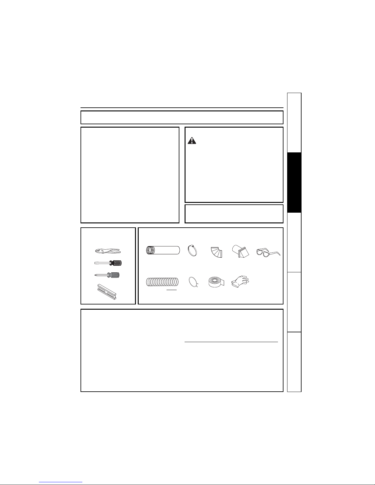
Installation Instructions