SP Scientific FTS SYSTEMS LYO-SEA User manual

SAMPLE EXTRACTOR ASSEMBLY OPERATOR’S MANUAL
FTS
S
YSTEMS
L
YO
-SEA
FOR
V
IR
T
IS
G
ENESIS
S
AMPLE
E
XTRACTOR
A
SSEMBLY


Rev 002, 04/11 i
© SP Scientific 2011
Copyright © 2011 SP Scientific. All marks herein are used under license.
All brand or product names mentioned may be trademarks or registered trademarks of their respective
companies.
Part Number 100003254
Rev 002, 04/11
SP Scientific
815 State Route 208
3538 Main Street
Gardiner, NY 12525 USA
Stone Ridge, NY 12484 USA
(800) 431-8232
(845) 255-5000
SP Service
(877) 548-4666
SP Service Fax
(845) 687-0024
Website
http://www.spscientific.com/
This Sample Extractor Assembly Operator’s Manual contains confidential and proprietary information of
SP Scientific and may be used only by a recipient designated by and for purposes specified by SP
Scientific.
Reproduction of, dissemination of, modifications to, or the creation of derivative works from this Sample
Extractor Assembly Operator’s Manual, by any means and in any form or manner, is expressly prohibited,
except with the prior written permission of SP Scientific. Permitted copies of this document must retain all
proprietary notices contained in the original.
The information in this document is subject to change without prior notice. Always confirm with SP
Scientific that you are using the most current version of this document. SP Scientific is free to modify any
of its products and services, in any manner and at any time, notwithstanding the information contained in
this document.
THE CONTENTS OF THIS DOCUMENT SHALL NOT CONSTITUTE ANY WARRANTY OF ANY KIND,
EITHER EXPRESSED OR IMPLIED, INCLUDING BUT NOT LIMITED TO THE IMPLIED WARRANTIES
OF MERCHANTABILITY AND/OR FITNESS FOR A PARTICULAR PURPOSE OR GIVE RISE TO ANY
LIABILITY OF SP SCIENTIFIC, ITS AFFILIATES OR ITS SUPPLIERS.
The terms and conditions governing the use of this Sample Extractor Assembly Operator’s Manual shall
consist of those set forth in written agreements with SP Scientific.

ii Rev 002, 04/11
© SP Scientific 2011
Important Symbols
WARNING!
INJURY OR EVEN DEATH
MAY RESULT IF A
RECOMMENDATION MARKED
WITH THIS SYMBOL IS NOT
HEEDED.
CRUSH HAZARD. KEEP HANDS
CLEAR WHEN OPERATING DOOR.
ELECTRIC SHOCK DANGER!
USE APPROPRIATE CAUTION
TO AVOID INJURY OR DEATH.
CORROSIVE CHEMICAL. WEAR
SUITABLE GLOVES, SAFETY
GLASSES, AND PROTECTIVE
CLOTHING.
BURN DANGER! POTENTIALLY
HOT SURFACE. USE
APPROPRIATE CAUTION.
PROPERTY CAUTION! TO PREVENT
DAMAGE TO CHAMBER EQUIP-
MENT AND/OR LOAD, ADHERE TO
PROCEDURES MARKED BY THIS
SYMBOL.
DO NOT STORE FLAMMABLE
MATERIALS IN CHAMBER.
PRACTICAL OPERATING TIP.
THESE RECOMMENDATIONS
STREAMLINE UNIT OPERATION
AND PREVENT COMMON
OPERATOR ERRORS.
WEAR SAFETY GLASSES.
EXPLOSIVE MATERIALS HAZARD!
KEEP OBJECTS AWAY FROM HEAT.
Freeze Dryer Safety Warnings
Always assume that shelf, condenser and internal parts may be very cold or very hot. Wear protectiveequipment to avoid burns.
Always ensure that only an authorized technician services the refrigeration, heat transfer, vacuum and electricalsystems.
Always ensure that the refrigeration air intake is clear and clean.
Always ensure vacuum pump exhaust is properly ventilated and/or contained.
Always practice team lifting when moving heavy equipment.
Always use a maximum one pound regulator if backfilling from an inert gas source.
Always wear safety glasses when using glass flasks.
Be sure to carefully read the entire instruction manual before attempting to operate the freeze dryer.
Be sure to verify that the electric service and other utilities match the unit’s requirements before connecting topower.
Never allow hand or body contact with open vacuum ports.
Never clean with solvents. Use mild detergent and water only.
Never operate the unit without all covers in place.
Never pressurize a freeze-drying chamber unless it has been specially designed and coded as a pressurevessel (e.g., displays an ASME-coded certificate).
Never stopper vials unless the chamber door is tightly closed.
Never use acrylic closures if they are cracked or crazed.
Never use with toxic, corrosive, flammable or organic materials unless special precautions are in place toprevent injury to personnel or damage to equipment.

Rev 002, 04/11 iii
© SP Scientific 2011
Warranty Information
FTS Systems Lyo-SEA for VirTis Genesis is warranted by SP Scientific to be free of defects in material and
workmanship when operated under normal conditions as specified in the instructions provided in this manual. Please
take this opportunity to locate the serial tag on your new FTS Systems Lyo-SEA for VirTis Genesis and record the
information below for future reference. SP Scientific also recommends that you complete and return your unit’s
warranty registration card.
Model Number
Serial Number
Part Number
Limited Warranty
SP Scientific (the “Company”) shall warrant each of its products against defects in material or workmanship for a period
of 12 months from the date of installation or 15 months from the date of shipment (whichever comes first) provided that
the product is used in a reasonable manner under appropriate conditions and consistent with the applicable operating
instructions.
The obligation of the Company shall be, at its option, to repair or replace, without charge any parts that prove to be
defective within the warranty period, if the purchaser notifies the Company promptly in writing of such defect. No
product shall be returned to the Company without prior approval of the Company.
This limited warranty shall cover the costs of parts and labor to repair or replace all defective product(s) at the Seller’s
factory. For all products installed by the Company and located within the Company service travel areas, this warranty
shall cover transportation charges to ship the product to and from the Company’s factory and/or the costs of travel,
room and board if the Company’s employees conduct repair at the Buyer’s location. In lieu of repair or replacement at
the Company’s factory, the Company may, in its discretion, authorize a third party to perform the repair or replacement
at the Buyer’s location, and at the Company’s sole expense.
The Company shall not be responsible for labor charges payable with respect to persons other than Company
employees. Replacement or repair of parts pursuant to this warranty shall not in any way extend the original warranty
period. The Company shall not be responsible for any unauthorized repairs, replacements or product modifications, nor
will it be responsible for any product failures resulting from such unauthorized repairs, replacements or product
modifications negligently or otherwise made by persons other than Company employees or authorized representatives
of the Company. The buyer shall assume transportation charges to ship the product to and from the Company’s factory
and the costs of travel, room and board if the Company’s employees conduct repair at the Buyer’s location within the
warranty period if the product was not installed by the Company’s and/or is not located within the Company’s service
travel areas.
THE COMPANY DOES NOT MAKE AND EXPRESSLY DISCLAIMS ANY WARRANTY OF MERCHANTABILITY OR
FITNESS FOR A PARTICULAR PURPOSE OR ANY OTHER WARRANTY, EXPRESSED OR IMPLIED, WITH
RESPECT TO THE SALE, INSTALLATION, DESIGN OR USE OF ITS PRODUCTS. ADDITIONALLY, THE
COMPANY SHALL NOT BE LIABLE FOR ANY CONSEQUENTIAL DAMAGES RESULTING FROM THE USE OF OR
ANY DEFECTS IN ITS PRODUCTS.
The Company’s employees are available to provide general advice to customers concerning the use of the Company’s
products; however, oral representations are not warranties with respect to particular products or their uses and may not
be relied upon if they are inconsistent with the relevant product specifications for the items set forth herein.
Notwithstanding the above, the terms and conditions set forth in the Company’s formal sales contracts shall be
controlling and supersede any inconsistent terms contained herein, and any changes to such contracts must be made
in writing and signed by an authorized executive of the Company.
WARNING! THE DISPOSAL AND/OR EMISSION OF SUBSTANCES USED IN
CONNECTION WITH THIS EQUIPMENT MAY BE GOVERNED BY VARIOUS FEDERAL,
STATE OR LOCAL REGULATIONS. ALL USERS OF THIS EQUIPMENT ARE URGED TO
BECOME FAMILIAR WITH ANY REGULATIONS THAT APPLY IN THE USERS AREA
CONCERNING THE DUMPING OF WASTE MATERIALS IN OR UPON WATER, LAND OR
AIR AND TO COMPLY WITH SUCH REGULATIONS.

iv Rev 002, 04/11
© SP Scientific 2011

Rev 002, 04/11 v
© SP Scientific 2011
Contents
Important Symbols...............................................................................................................................................ii
Freeze Dryer Safety Warnings.............................................................................................................................ii
Warranty Information .......................................................................................................................................... iii
Introduction .................................................................................................................1
Extractor Components .........................................................................................................................................1
Installation...................................................................................................................3
Standard Door Removal ......................................................................................................................................3
Operation ....................................................................................................................5
Operation.............................................................................................................................................................5
Shelf Spacing.......................................................................................................................................................9

Contents
FTS Systems Lyo-SEA for VirTis Genesis
vi Rev 002, 04/11
© SP Scientific 2011
Rev 002, 04/11 1
© SP Scientific 2011
Chapter
1
Introduction
The optional Lyo-SEA Sample Extractor allows you to select and remove a serum
bottle or vial from the product chamber at any time during a freeze-dry run. The
selection and removal process is achieved with virtually no interruption to the drying
process. The simplicity of the design and ease of use provides a cost effective
methodology for periodic removal of product for sample analysis. The Sample
Extractor is often pivotal in product development or stability studies.
Note: The Lyo-SEA Sample Extractor requires the use of an auxiliary vacuum pump to
depressurize the antechamber.
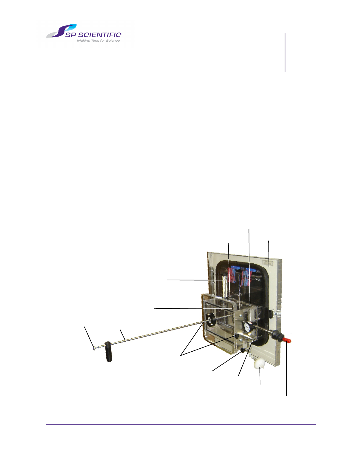
Extractor Components
The Lyo-SEA Sample Extractor is comprised of a modified acrylic door with the
following components:
Stoppering Ram
Acrylic Door
Vacuum Antechamber
Vacuum Gauge
Jaw Controls
Selector Arm
Thumbscrews
Inert Gas Backfill / Vacuum Break
Vacuum Pump
Inlet
Filter
Isolation Door Lock / Handle
Antechamber Isolation Door

Introduction
FTS Systems Lyo-SEA for VirTis Genesis
2 Rev 002, 04/11
© SP Scientific 2011

Rev 002, 04/11 3
© SP Scientific 2011
Chapter
2
Installation
Standard Door Removal
Before installing the Lyo-SEA Sample Extractor, the standard acrylic door must be
removed from the freeze-dryer.
To remove the door:
Ensure that the unit is not in operation and that the product chamber is not1. under vacuum.
Remove the left side panel from the unit.2.
Open the product chamber door. Have an assistant in position to support the3. door.
Remove the existing product chamber door and hinge bracket by removing4. the four hex nuts and two spacers. Slide the assembly outward through the
frame in an upright position.
Install the door of the Lyo-SEA with hinge stands into the frame. Reuse the5. tube spacers and hardware from the original assembly.
Close the door.6.
Adjust the hinge stands so that the chamber gasket presses evenly when the7. door is in the closed position. This is accomplished by tightening the nuts on
the hinge. When proper contact is achieved, a dark black surface should be
visible between the acrylic door and the chamber gasket surface.
Re-install the left side panel.8.
Hex Nut
Spacer
Hinge Bracket
Frame
Hinge Bracket Assembly (Top View)
Lyophilizer
Front Panel
Hex Nut
Acrylic Lyo-SEA Door
Hinge Stand
(Top)

Installation
FTS Systems Lyo-SEA for VirTis Genesis
4 Rev 002, 04/11
© SP Scientific 2011
Rev 002, 04/11 5
© SP Scientific 2011
Chapter
3
Operation
Before beginning operation of the Lyo-SEA Sample Extractor, ensure that the front
plate is closed and that the inert gas/vacuum break valve is closed.
Operation To operate the Lyo-SEA Sample Extractor:
Activate the auxiliary vacuum pump to depressurize the antechamber.1.
After the gauge stabilizes at the maximum position, allow the vacuum pump to2. operate for an additional 15 minutes.
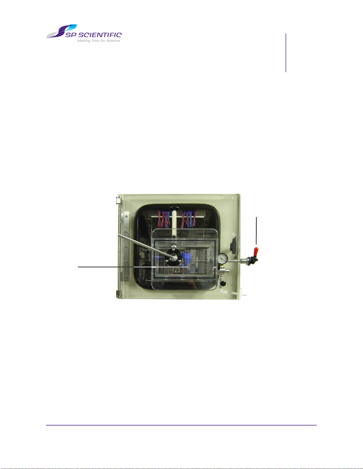
Open the antechamber isolation door. With locking handle in the up position3. (unlocked), slide the antechamber door open.
When the antechamber isolation door is fully open, you may lower the handle4. to lock the isolation door in position.
Antechamber Isolation Door
Raise handle to
unlock door.

Operation
FTS Systems Lyo-SEA for VirTis Genesis
6 Rev 002, 04/11
© SP Scientific 2011
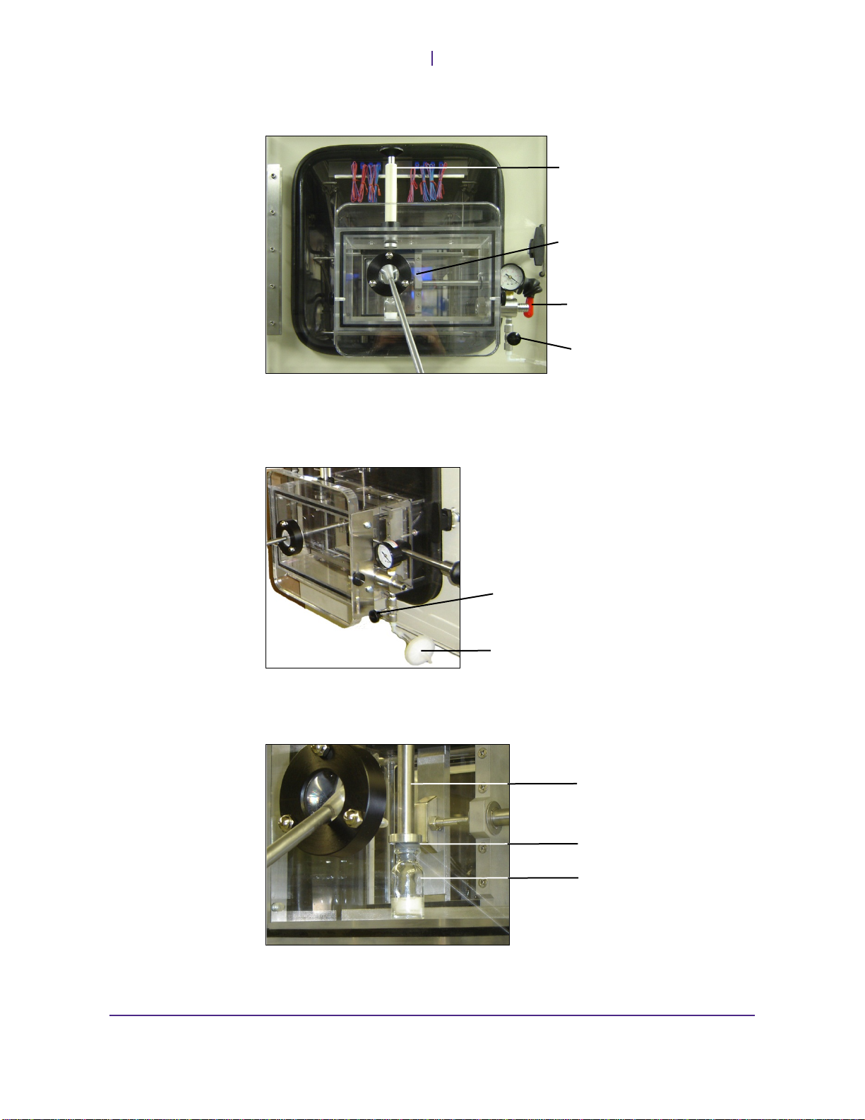
Manipulate the selector arm to select and extract vial(s).5.
Vials are held securely in spring-loaded jaws. Push the button on the selector6. arm to open the jaws. Release the button to close the jaws.
Place a sample in the antechamber directly beneath the stoppering ram.7.
Push button on selector
arm to open jaw.
Vial held in spring-loaded
jaws. Push button on
selector arm to open jaws
and release vial.
Vial placed beneath
stoppering ram.
Stoppering Ram
FTS Systems Lyo-SEA for VirTis Genesis
Operation
Rev 002, 04/11 7
© SP Scientific 2011
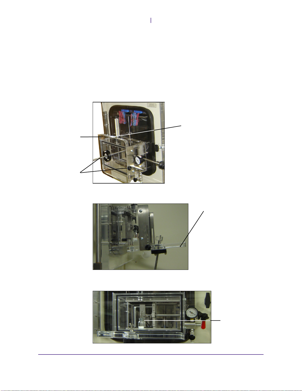
Slide the isolation door closed and lower the handle to lock it into position.8.
Prior to stoppering the sample, you may backfill the antechamber with an inert9. gas, such as nitrogen (N2(gas)) via the vacuum break valve. Connect your inert
gas source to the vacuum break valve via the filter attachment.
Remove the plastic shroud from the stoppering ram. Press down on the10. stoppering ram to manually stopper the vial.
Handle lowered to
lock isolation door
into position.
Isolation Door
Vacuum Break Valve
Plastic Shroud
(Stoppering Ram)
Stoppering Ram
Vial Sample
Stopper
Connect an inert gas source
to the vacuum break valve via
the filter attachment.
Vacuum Break Valve
Operation
FTS Systems Lyo-SEA for VirTis Genesis
8 Rev 002, 04/11
© SP Scientific 2011
Before the sample can be removed from the antechamber, the antechamber11. pressure must be returned to atmospheric pressure. If you have connected an
inert gas source for backfilling, remove it now. Open the vacuum brake valve
to release vacuum from the antechamber. Allow the antechamber to return to
atmospheric pressure.
Loosen the thumbscrews on each side of the antechamber and push down on12. the front plate until it can be opened.
Note: Vacuum pressure in the chamber will cause the antechamber front plate gasket
to seal. In order to break the seal, you may need to apply force initially when sliding
down the front plate.
Flip down the front plate.13.
Remove the vial(s).14.
Close the front plate to reseal the antechamber.15.
Thumbscrews
Antechamber
Front Plate
Push down on the
front plate until it can
be opened. You may
need to apply force
initially.
Antechamber
Front Plate
Vial Sample

FTS Systems Lyo-SEA for VirTis Genesis
Operation
Rev 002, 04/11 9
© SP Scientific 2011
Shelf Spacing
Certain applications of the Lyo-SEA sample thief may require shelf spacing
adjustments.
To adjust shelf spacing:
Ensure that all shelves are empty before continuing.1.
Press and hold the stoppering switch in the Down position to allow the shelf2. stack to compress fully.
Remove the four (4) upper shoulder screws and install latching rod3. extensions. Remove only the upper shoulder screws installed in the four
corners of the top shelf.
Replace and secure the four (4) upper shoulder screws.4.
Press and hold the stoppering switch in the Up position to allow the shelf5. stack to extend and return to its original position. The second product shelf
(now located near the bottom of the chamber) may be loaded with product.
Insert a corrugated shelf spacer on the first product shelf to ensure sufficient6. cylinder stroke to stopper the vials.
To return the shelves to their original configuration, repeat the process and7. remove the latching rod extensions. Ensure that the shoulder screws are
secured before extending the shelf stack.
Note: The top shelf is the radiant heat shelf and is not appropriate for product. The
shelf below the top shelf is the first "product" shelf, while the shelf below that is the
second "product" shelf, and so on. If the Lyo-SEA sample thief is retrofitted to an
existing Genesis unit, the four (4) latching rods will have to be installed on the first
product shelf. Latching rods are included in the accommodation kit.

Operation
FTS Systems Lyo-SEA for VirTis Genesis
10 Rev 002, 04/11
© SP Scientific 2011


Table of contents
Popular Scrubber manuals by other brands


BGS technic
BGS technic 9910 quick start guide

Global Industrial
Global Industrial 604153 user manual

Kärcher
Kärcher BR/BD45/40C Bp Original instructions

Wetrok
Wetrok Duomatic Esprit operating instructions

BM2 BIEMMEDUE
BM2 BIEMMEDUE WET 850 BA operating manual

Kärcher
Kärcher KM 100/100 R Bp Pack Operator's manual