STOLZENBERG TT 1200 User manual

TT 1200
htttp://www.stolzenberg.de
!
Service Manual
EN

2

1 CLEANING AND MAINTENANCE
The regular maintenance of the sweeper serves to preserve the
machine, its components and the sweeping result. If performed
regularly, the subsequently described maintenance work can
extend the lifetime of the equipment!
ATTENTION - Personal protective equipment in
the form of goggles, breathing protection and
gloves must be worn for interior and exterior
cleaning of the sweeper!
To clean the machine interior, the main cover must be opened and
secured by means of the main cover holder. Use a dry cloth for
cleaning and blow through the machine with compressed air.
Subsequently close the main cover properly once again.
For the exterior cleaning of the sweeper, use compressed air
and/or a cloth or a wash mitt moistened with warm water or a mild
detergent solution.
Safety instructions for cleaning and
maintenance
1.1
GENERAL CLEANING AND MAINTENANCE INSTRUCTIONS1.2
ATTENTION - For safety reasons, all cleaning and
maintenance work may only be carried out when
the machine is switched off! To do so, remove the
key from the device! Failure to do so may result in
serious injury!
For cleaning and maintenance intervals, please refer to the service
indicator
(§ see page 37 ) or the maintenance manual!
All service and maintenance work must be performed by a
qualified technician! If necessary, a Stolzenberg dealer can be
contacted at any time! You can find the relevant dealer or service
technician for your machine on the manufacturer website!
MAINTENANCE OF THE SWEEPING SYSTEM1.3
1.3.1 Maintenance of the sweeper roller drive
To maintain functioning, the sweeper roller should be inspected
regularly for wear on the drive chain and pinions. Furthermore, the
chain elongation must be measured regularly. For this purpose,
ten rolls are counted at an arbitrary position on the chain (ideally
in the pull strand) and the inner tangential distance between them
is measured with a calliper. If the value is between 79.3 mm and
81.8 mm, then the chain is still in order. A measured length of 81.9
mm or above indicates that the chain should be replaced, because
the wear of the pinions will be increased as of this value!
3
IMPORTANT - Do not use aggressive cleaning
agents!
ATTENTION - The sweeper may not be cleaned
using high-pressure or water jet, as these can
cause damage! There is a danger of short circuit
or other serious damage!
Contents
1 Cleaning and maintenance
1.1 Safety instructions for cleaning and maintenance
1.2 General cleaning and maintenance instructions
1.3 Maintenance of the sweeping system
1.3.1 Maintenance of the sweeper roller drive
1.3.2 Adjusting the sweeping pattern
1.3.3 Sweeper roller replacement
1.3.4 Maintenance of the side brush unit
1.3.5 Re-adjusting the side brush
1.3.6 Side brush replacement
1.4 Maintenance of the filter system
1.4.1 Maintenance of the fan
1.4.2 Filter replacement
1.4.3 Cleaning the filter
1.5 Battery setting & maintenance
1.5.1 Setting the battery type
1.5.2 Checking the battery status
1.6 Steering maintenance
1.6.1 Control and readjustment of the chain tension
1.6.2 Control of slide bearings
1.7 Maintenance of wheels
1.7.1 Rear wheel replacement
1.7.2 Front wheel replacement
1.8 Maintenance of the brake
1.8.1 Inspection of brake pads
1.8.2 Readjustment of the brake
1.9 Changing the machine settings
1.9.1 Setting options for end users
1.9.2 Setting options for service technicians
1.10 Resetting the service counter
2 Wiring diagrams
2.1 Wiring diagram basic version
2.2 Wiring diagram left side brush option
2.3 Wiring diagram light option
2.4 Wiring diagram on-board charger option
2.5 Wiring diagram backward signal
3 Accessories and spare parts
4 Warranty
5 Transport of the sweeper
6 Maintenance Plans
6.1 Maintenance work for machine owners
6.2 Maintenance work for service center
6.2.1 Service I
6.2.2 Service II
6.2.2 Service II
7 Maintenance Proof
8 Contact
..............................................................3
.............3
.................3
...................................3
.........................3
.........................................4
...............................................6
...................................8
.................................................9
.....................................................10
..........................................11
......................................................11
...............................................................11
................................................................16
.............................................17
.....................................................17
..............................................18
.............................................................19
...........19
...................................................22
...........................................................22
....................................................22
..................................................24
.......................................................26
...................................................26
................................................27
.............................................27
...........................................27
.........................28
................................................30
...............................................................................31
................................................31
................................32
...................................................33
...........................34
..........................................35
..........................................................36
.............................................................................................36
...............................................................36
..........................................................................38
..............................38
..................................38
.................................................................................38
................................................................................38
................................................................................38
...........................................................................39
...............................................................................................40
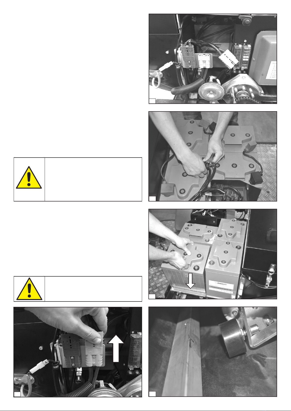
ATTENTION - Do not place any tools on the
batteries. This could short-circuit the batteries
and lead to the explosion of the batteries! It is
necessary to ensure that no connection can be
established between the battery terminals.
Special terminal protectors or electrical tape can
be used for this purpose.
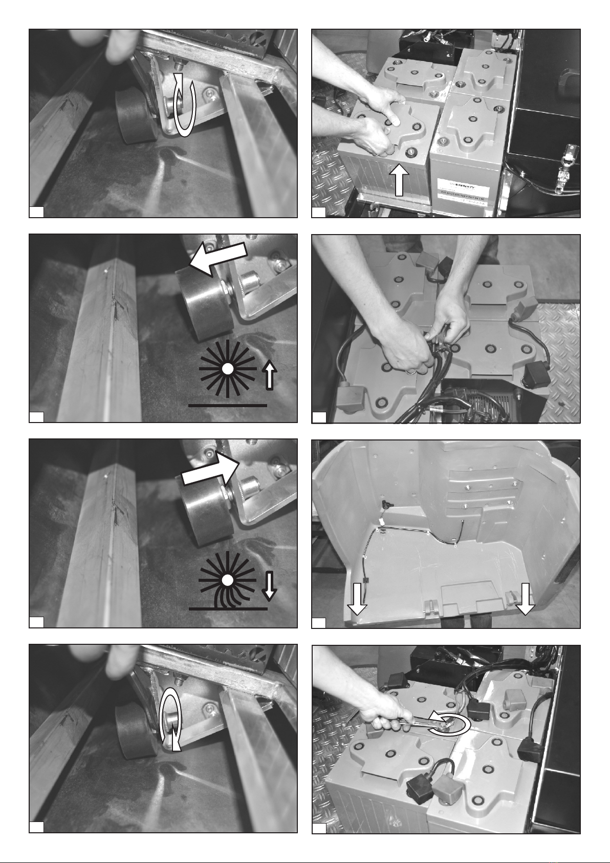
NOTE - Since the position of the stop buffer must
be adjusted depending on the surface, it may be
necessary to repeat the steps described above
several times.
2
1
4
5
3
4
Now both batteries at the front (in driving direction) can be
removed from the machine (4) to allow access to the sweeper
roller's depth stop buffer (5). To be able to turn the stop buffer, it is
necessary to loosen the locknut (6). To reduce the sweeping
pattern, the stop buffer is rotated clockwise (7) and to enlarge the
pattern, it is rotated counterclockwise (8). After the adjustment,
the locknut must be tightened again (9). Now the batteries can be
inserted and connected to the wiring harness (10-11). The
assembly of the main cover and the connection of the battery
connector (12-13) are the final steps to make the machine ready
for use once again.
The sweeper roller driving chain should be treated regularly with a
non-adhesive, solvent-based lubricant (e.g. B. Innotech 105) to
remove dirt particles and to maintain the lubricating film between
the individual chain elements and between the chain and the
pinions.
1.3.2 Adjusting the sweeping pattern
The sweeping pattern does not need to be set manually for this
sweeper. When the main sweeper roller motor is started, the
automatic lowering mechanism lowers the rear sweeper roller to
the floor, until a certain contact pressure is reached. The automatic
lowering mechanism can thus also ensure wear re-adjustment, so
that a consistently good sweeping result is achieved. For certain
applications - on carpets in particular - the pre-set pressure may,
however, be too high. In this case, a depth limitation can be set for
the automatic lowering mechanism.
The stop buffer required for the depth limitation is located
beneath the batteries. To access it, you first have dismantle the
main cover § see chapter 4.5.2 at the Operating Manual
Subsequently, the battery plug must be removed (1-2) to break the
connection between the machine and the batteries. Now the
battery terminals of the batteries can be loosened (3).
13
12
11
8
7
6
9
10
5

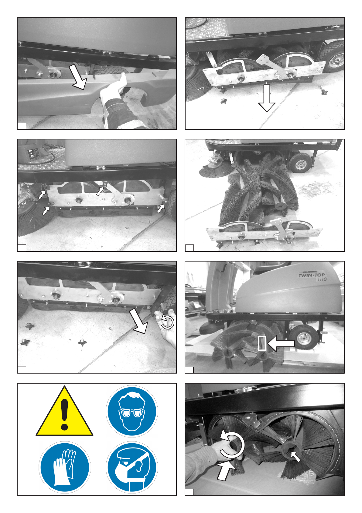
1.3.3 Sweeper roller replacement
For sweeper roller replacement, start by dismounting the left side
cover. For this purpose, start by removing the hopper (1). The
knurled nut to fasten the side cover on the machine frame is now
accessible (2) and must be removed (3). In the next step, the front
fixation of the side cover must be loosened (4-5). Now the side
cover can be removed (6). The lateral sweeper roller tunnel cover,
which is secured with four star grip nuts, is now accessible (7).
These nuts must now be loosened (8).
ATTENTION - Personal protective equipment in
the form of goggles, breathing protection and
gloves must be worn when removing the
sweeper rollers!
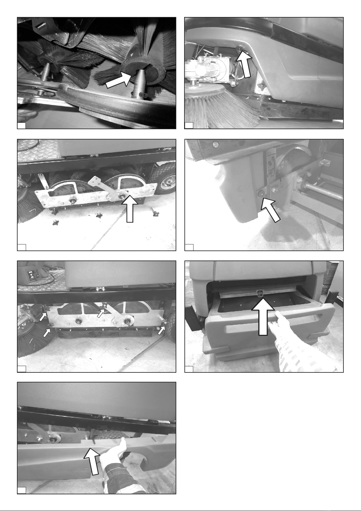
Then the lateral sweeper roller tunnel cover can be pulled off to
the side (9). The sweeper rollers are now freely accessible (10) and
can be replaced with new sweeper rollers. The correct mounting
orientation must be observed when inserting the new sweeper
rollers (11). The wear indicator (red bristles) must be visible on the
rear sweeper roller, i.e. it should point to the left in the driving
direction. For the front sweeper roller, the wear indicator must not
be visible, i.e. it should point to the right in the driving direction. It
is also important to ensure that the clamping pins at the engaging
elements (12) correctly engage the sweeper rollers. For this
purpose, the sweeper roller is inserted into the sweeper roller
tunnel and pushed on to the driving element with a slight twist
(13). The snapping of the sweeper roller into the clamping pin of
the driving element is ensured when the sweeper roller can no
longer be turned at all or only to a very limited extent. If the
sweeper roller is inserted correctly, the side sweeper roller tunnel
cover can be mounted again and secured with the corresponding
star grip nuts (14-15). Finally, the side cover is attached (16) and
fixed with the knurled nuts (17-18). After insertion and locking of
the dust box (19), the machine is once again ready for use.
1
3
4
2
5
6
6
7
8
9
10
12
11
7
14
15
16
17
1.3.4 Maintenance of the side brush unit
The side brush driver unit is a direct drive, which can be
considered as free of wear. It should however be checked at
regular intervals, to confirm that the swivelling mechanisms of
the side brush arm is still functioning properly and smoothly.
For this purpose, the side brush must first be set to the working
position (arrow on the side brush adjustment lever pointing
downwards (1). Now the side brush arm on the side brush cover
is pressed completely towards the machine centre (2), after
which the cover must be completely immersed under the
machine frames (3-4). When the side brush arm is released, it
must fully swivel back to its original position (5). It may happen
that the complete spring-back only takes place after the side
brush is switched on, because the bristles create a slight
resistance on the floor.
18
19
13
8

1.3.5 Re-adjusting the side brush
To re-adjust the side brush in case of wear, it suffices to adjust a
screw that is attached to the side brush adjustment unit and which
forms the depth stop of the side brush. In order to access the
setting screw, the side brush adjustment lever must first be moved
to the upper position (with the arrow on the side brush adjustment
lever pointing upwards (1). The setting screw behind the side
brush adjustment lever is now accessible and visible from the
footwell (2). By turning the setting screw clockwise (3), the depth
stop of the side brush is lowered (4), by turning the setting screw
counter-clockwise (5), the depth stop of the side brush is raised
(6).
5
4
3
1
2
1
2
9

The adjustment of the correct contact zone is essential for the
sweeping result. If an insufficient number of bristles touch the
floor (A), then the sweepings are not directed to the machine
centre, but rather thrown forward obliquely. If the bristle bed of
the side brush is too large (C), then it is possible that sweepings are
passed in front of the main sweeper roller and ejected laterally.
The side brush is considered correctly adjusted if the bristles in
line with the side brush arm touch the floor in a sickle-shape of
approx. 120° (B).
1.3.6 Side brush replacementSeitenbesenwechsel
The side brush is fixed to the side brush motor with a screw. To
reach this easily, the side brush should be brought to the rest
position (1). The wing screw used for fixation is positioned
centrally on the underside of the side brush (2) and must now be
unscrewed (3) to remove the side brush from the motor (4).
When installing the new side brush, it is necessary to ensure that
the lug on the side brush engaging piece (5) engages in the feather
key groove of the motor shaft when mounting the side brush onto
the drive motor (6). The side brush must now only be fastened with
the wing screw (7) before it is ready for use.
3
4
5
6 1
2
10
BA C
~120°

3
4
6
5
7
8
MAINTENANCE OF THE FILTER SYSTEM1.4
1.4.1 Maintenance of the fan
The fan of this sweeper is a maintenance-free component. It only
needs to be checked regularly to see if any foreign objects are
inside the fan or whether the fan generates amplified or unusual
noise.
ATTENTION - Personal protective equipment in
the form of goggles, breathing protection and
gloves must be worn when removing and
replacing the filter!
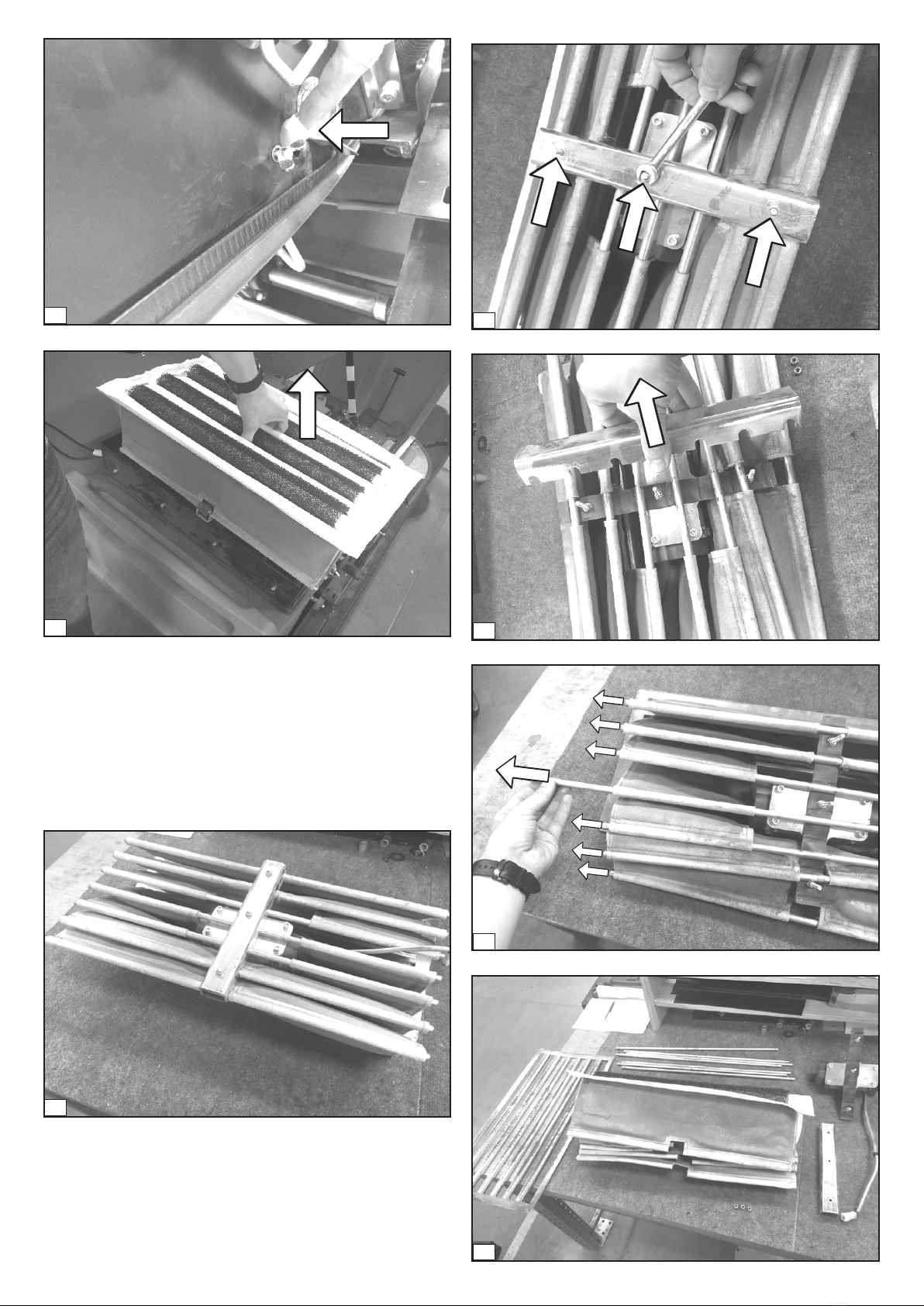
1.4.2 Filter replacement
1.4.2.1 Removing the filter unit
In order to remove the filter unit, it is initially necessary to open
the main cover and to secure it with the main cover bracket (1). In
the next step, the filter chamber cover must be removed. For this
purpose, the power supply of the fan is disconnected (2), the
clamps of the filter chamber cover attachment are loosened (3)
and the filter chamber cover is removed upwards (4). The filter unit
is now freely accessible (5). In order to remove it, the power
connector of the filter vibrator must be disconnected (6), the plug
feedthrough must be opened (7-8) and the plug must be pushed
inside the filter chamber (9). The entire filter unit can now be
removed upwards from the filter chamber (10).
11

4
5
6
7
8
3
1
2
12
9
10
1.4.2.2 Disassembling the filter unit
Place the filter unit upside down on a workbench/table for
disassembly (1). Then start by unscrewing the three screws of the
clamping plate (2). Remove the clamping plate (3) and laterally
pull out the seven vibrating rods from the filter bags (4). The entire
filter unit is now disassembled (5).
5
1
2
3
4
13
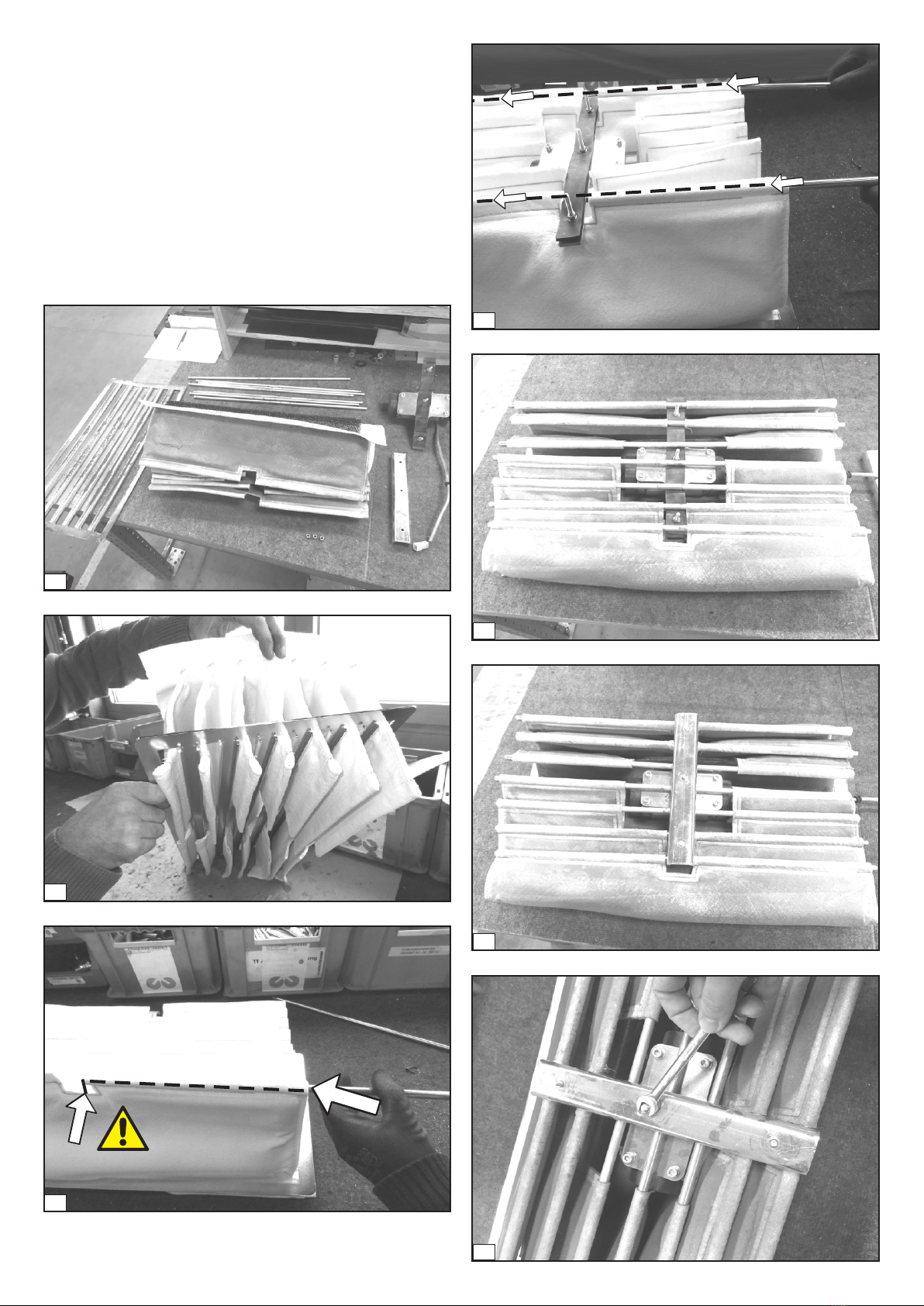
1.4.2.3 Mounting the filter unit
To assemble the filter unit, the filter bags must first be threaded
through the filter grid. It is important to make sure that the folds of
the filter grid point downward (2) in the installed state (inside the
machine)! In the next step the vibrating rods are threaded through
the filter loops laterally until the mark (3). The vibrator motor is
now positioned centrally on the pre-assembled filter unit (4). Now
the vibrating rods are pushed through the filter loops completely
(5). The vibrating rods are now placed on the rubber at the filter
vibrator (6), the clamping plate is mounted (7) and fixed with the
nuts (8). The filter unit is now ready for installation in the sweeper
(9).
1
2
5
7
6
14
3
4
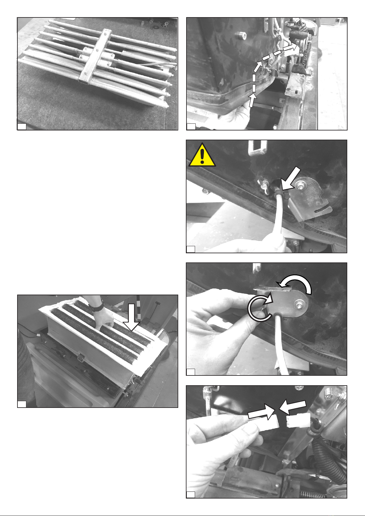
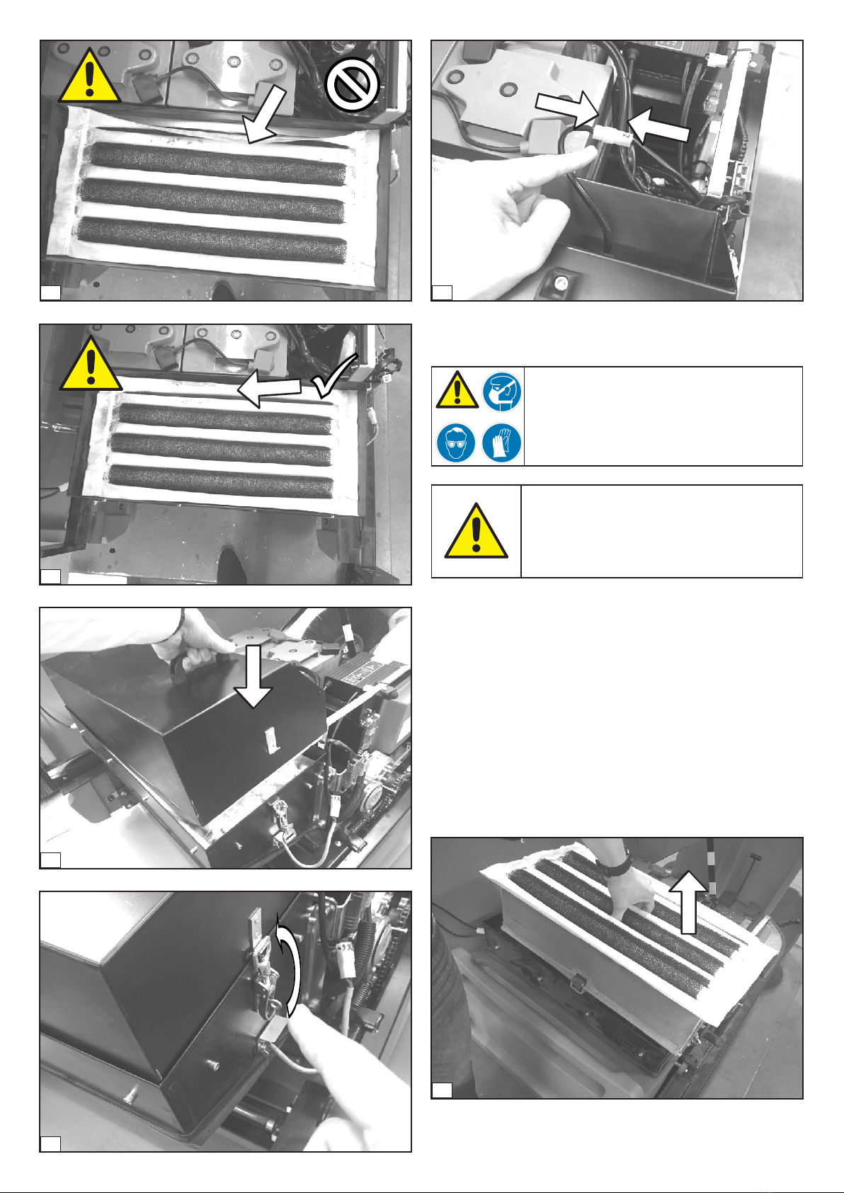
1.4.2.4 Installing the filter unit
The pre-assembled filter unit is inserted into the filter chamber
from above (1) and the filter vibrator cable is pushed through the
cable feedthrough from the inside (2). It is important that the
cable grommet is mounted correctly on the filter vibrator cable at
the designated position on the cable feedthrough (3). Then close
and fasten the cable feedthrough (4) and restore the power
connection to the filter vibrator (5). Before the filter chamber
cover is put back in place, it must be ensured that the filter rests
properly and smoothly on the filter grid (6-7). If this is not the case,
dust can be suctioned past the filter, which has a strong negative
effect on the filtration result! If it is ensured, place the filter
chamber lid with the ventilation openings facing backwards in the
driving direction onto the filter from above (8), lock it with the
side-mounted turnbuckles (9). The turnbuckles are mounted
asymmetrically to prevent incorrect installation of the filter
chamber lid. Finally, the power supply of the fan needs to be
restored (10).
1
3
4
5
8 2
15
10
7
8
9
1.4.3 Cleaning the filter
ATTENTION! RISK OF INJURY! - Always wear
your personal protective equipment in the form
of protective goggles, gloves and breathing
protection when cleaning the filter!
NOTE! Never clean the filter with water or other
(chemical-containing) liquids. This would
damage the filter beyond repair!
To clean the filter, it should be removed from the machine as
described in section (1). Filter carrier, vibrating rods and vibrator
motor must not be disassembled for cleaning.
The filter can now be cleaned, ideally by means of compressed air
from the clean side (2). Never clean the filter from the dust side (3),
since the dust present on the filter would be pressed into the filter
pores and the filter performance would be fundamentally
reduced! Now mount the filter unit once again into the sweeper as
described in section .
The cleaning interval to be observed is strongly dependent on the
environment to be swept. For moderate dust concentrations,
cleaning with compressed air is recommended every 10 hours.
1
6
16

3
4
BATTERY SETTING & MAINTENANCE1.5
1.5.1 Setting the battery type
A distinction is made essentially between gel and acid batteries,
which have different discharge curves and shutdown thresholds.
To ensure proper battery indication and proper discharge
protection, it is thus necessary to select the right type of battery in
the settings menu of the control system. To do this, select the
menu item "Settings" in the main menu of the control system (1)
and sign-in with your access code (2). You have now entered the
settings menu (3). Now switch to the menu item "Battery type" (4)
and select the installed battery type from the sub-menu (5-6).
After selecting the battery type, you switch to the menu item "Exit
settings" (7). Now select "Save and Exit" (8). You have now
returned to the main menu of the control system.
1
4
3
2
2
17

8
6
7
1.5.2 Checking the battery status
AT TE N T IO N ! - O n ly u se t h e c h arge r s
recommended by the manufacturer of this
sweeper to charge this machine! Using the
wrong charger or the wrong setting can damage
the batteries!
The best way to determine the battery state is by measuring the
battery voltage in the charged state. For this purpose, the batteries
must first be fully charged (1-2). Subsequently, a voltmeter is
connected (3-4) between the positive pole of the first battery and
the negative pole of the last battery. For identification: The poles
to be measured are those that are connected to the main cable
strand of the machine (3). If the voltmeter displays a voltage
between 25.5 V and 24.5 V, the battery is still in good condition. If
the indicated voltage lies between 24.5 V and 23.5 V, the battery is
in a sufficient condition, however, the machine running time is
already reduced. For a reading below 23.5 V, new batteries should
be inserted!
2
100%
5
18
1

4
25,5V – 24,5V
24,5V – 23,5V
< 23,5V
STEERING MAINTENANCE1.6
1.6.1 Control and readjustment of the chain tension
If the steering clearance on the steering wheel is too large, then
this indicates that the chain tension is too low. Typically, a steering
clearance up to 1 cm is acceptable in each direction. Greater
steering clearance must be reduced by adjusting the chain
tension.
NOTE! - A certain steering clearance is common.
A too high chain tension can cause steering noise
and increase wear on the chain and the pinions!
1
2
The chain tension is being increased by adjusting the sprocket.
Therefore the screws of the adjustment plate and excenter plate
will be loosened. Then the adjuster plate can be moved backwards
by turning the excenter plate. Move the adjuster bracket as long as
the chain is tensioned properly and fasten the screws.
3
1cm =
> 1cm =
19

6
5
8
7
9
10
4
3
20
Other manuals for TT 1200
1
Table of contents
Other STOLZENBERG Scrubber manuals


