Space ER 200 User manual
INSTRUCTION MANUAL
SPACE s.r.l. ER 200 - ER 220
ER150 - ER160 - ER165
Code M0076 - rev.1.6
(04/2005)
SPACE s.r.l. – 10090 Trana (TO) Via Sangano, 48
Tel. (+39) 011/ 933.88.65 – Fax (+39) 011/ 933.88.64
e-mail: info@spacetest.com
COMPOSIZIONE COMPOSITION ZUSAMMENSETZUNG COMPOSITION COMPOSICIÓN
42 pagine (copertine
comprese)
42 pages (including
cover pages)
42 Seiten (inkl.
Deckblätter)
42 pages (pages de la
couverture incluses)
42 páginas (incluidas
las portadas)
40 pagine numerate 40 numbered pages 40 numerierte Seiten 40 pages numérotées 40 páginas numeradas
• Per eventuali chiarimenti interpellare il più vicino rivenditore oppure rivolgersi direttamente a:
• For any further information please contact your local dealer or call:
• Im Zweifelsfall ober bei Rückfragen wenden Sie sich bitte an den nächsten Wiederverkäufer oder direkt an:
• Pour tout renseignement complémentaire s’adresser au revendeur le plus proche ou directement à:
• En caso de dudas, para eventuales aclaraciones, póngase en contacto con el distribuidor más próximo ó
diríjase directamente a:
SPACE ER 200 - ER 220
SPACE ER 150 - ER 160 - ER 165
MANUALE DI ISTRUZIONE
INSTRUCTION MANUAL
BETRIEBSANLEITUNG
MANUEL D’INSTRUCTIONS
MANUAL DE INSTRUCCIONES

INSTRUCTION MANUAL
SPACE s.r.l. ER 200 - ER 220
ER150 - ER160 - ER165
Code M0076 - rev.1.6
(04/2005)
SPACE s.r.l. – 10090 Trana (TO) Via Sangano, 48
Tel. (+39) 011/ 933.88.65 – Fax (+39) 011/ 933.88.64
e-mail: info@spacetest.com
SIMBOLOGIA UTILIZZATA NEL MANUALE
SYMBOLS USED IN THE MANUAL
IN DER BETRIEBSANLEITUNG VERWENDETE ZEICHEN
SYMBOLES UTILISES DANS LA NOTICE
SIMBOLOGÍA UTILIZADA EN EL MANUAL
SIMBOLI SYMBOLS ZEICHEN SYMBOLES SÍMBOLOS
VIETATO! FORBIDDEN! VERBOTEN INTERDIT! PROHIBIDO!
Obbligo!
Operazioni o
interventi da
eseguire
obbligatoriamente
Mandatory!
Operations or
jobs to be
performed
compulsorily
Vorschirift
Obligatorisch
auszuführende
Arbeitsvorgänge
oder Eingriffe
Obligation.
Opérations ou
interventions
obligatoires
Obigación.
Operaciones o
intervenciones que
hay que realizar
obligatoriamente
Pericolo!
Prestare
particolare
attenzione
Hazard!
Be especially
careful
Gefahr!
Äusserste
Vorsicht ist
geboten
Dager!
Faire trés
attention
Peligro!
Prestar especial
atención
Movimentazione
con carrello
elevatore o
transpallet
Handle using
fork-lift or pallet
transfer unit
Transport mit
Dabelstapler oder
Handgabelhub-
wagen
Déplacement
avec chariot
élévateur ou
traspalette
Desplazamiento
con carretilla
elevadora o
estibadora
Attenzione: carichi
sospesi
Caution: hanging
loads
Achtung:
hängende Lasten
Attention: charge
suspendue
Ateción: cargas
suspendidas
Attenzione: Non
sollevare mai la
macchina facendo
presa sull’albero
Caution: Never lift
the machine by
means of the
shaft
Achtung: Die
Maschine nie an
der Wuchtwelle
anheben.
Attention: ne
soulever pas
l‘équilibreuse en
ayant prise sur
l’arbre
Atención: no
levantar jamás la
máquina tomándola
por su eje
Pericolo: scariche
elettriche Shock hazard
Gefahr!
elektrische
Entladungen
Danger
d’électrocution
Peligro de
descargas
eléctricas
Indossare guanti
da lavoro Wear work gloves
Der Arbeit
angemessene
Handschuhe
tragen
Porter des gants
de travail
Colocarse guantes
de trabajo
Calzare scarpe da
lavoro Wear work shoes
Der Arbeit
angemessene
Schuhe tragen
Mettre des
chaussures de
travail
Usar zapatos de
trabajo
Indossare occhiali
di sicurezza
Wear safety
goggles
Schutzbrille
tragen
Porter des lunet-
tes de sécurité
Usar gafas de
seguridad

INSTRUCTION MANUAL
SPACE s.r.l. ER 200 - ER 220
ER150 - ER160 - ER165
Code M0076 - rev.1.6
(04/2005)
SPACE s.r.l. – 10090 Trana (TO) Via Sangano, 48 Page 1/ 40
Tel. (+39) 011/ 933.88.65 – Fax (+39) 011/ 933.88.64
e-mail: info@spacetest.com
LIST OF CONTENTS
0 INSTRUCTIONS ........................................................................................................................2
0.1 PRELIMINARY SAFETY INFORMATION ....................................................................................................................2
1 INTENDED USE.........................................................................................................................3
2 OPERATOR TRAINING...........................................................................................................4
2.1 GENERAL PREVENTIVE MEASURES.........................................................................................................................4
2.2 INDICATION OF OUTSTANDING RISKS .....................................................................................................................4
3 COMPOSITION OF EQUIPMENT .........................................................................................5
3.1 MODELS ER200 - ER220 ......................................................................................................................................5
3.2 MODELS ER150 - ER160 - ER165 ........................................................................................................................6
3.3 SAFETY DEVICES....................................................................................................................................................7
3.4 TECHNICAL DETAILS ..............................................................................................................................................7
3.5 OVERALL DIMENSIONS...........................................................................................................................................8
3.5.1 Models ER200 - ER220 ................................................................................................................................8
3.5.2 Models ER150 - ER160 - ER165 ..................................................................................................................8
4 TRANSPORT AND INSTALLATION.....................................................................................9
4.1 TRANSPORT AND UNPACKING ................................................................................................................................9
4.2 INSTALLATION .......................................................................................................................................................9
4.2.1 Fitting the shaft on the flange.....................................................................................................................10
4.2.2 Fitting the protection guard (mod. ER165 only) ........................................................................................10
4.2.3 Brightness and contrast adjustment............................................................................................................11
4.2.4 Power connections......................................................................................................................................11
5 FITTING THE WHEEL ON THE SHAFT............................................................................12
6 SWITCHING THE MACHINE ON AND OFF.....................................................................13
7 WHEEL BALANCING ............................................................................................................14
7.1 DETERMINATION OF WHEEL DIMENSIONS ............................................................................................................14
7.1.1 Manual setting of wheel dimensions for dynamic balancing and ALU 1, 2, 3, 4 functions ........................14
7.1.2 Wheel dimension manual setting for ALU-S type correction......................................................................16
7.1.3 Manual setting of wheel dimensions for static correction ..........................................................................17
7.2 USER MANAGEMENT ............................................................................................................................................18
7.3 UNBALANCE MEASUREMENT ...............................................................................................................................19
7.3.1 Dynamic balancing.....................................................................................................................................19
7.3.2 Wheel positioning .......................................................................................................................................21
7.4 ALU AND/OR STATIC PROGRAMS......................................................................................................................22
7.4.1 Static balancing ..........................................................................................................................................23
7.4.2 ALU-S procedure........................................................................................................................................25
8 WHEEL BALANCING IN MOTORCYCLE MODE...........................................................27
9 WEIGHTS HIDDEN BEHIND SPOKES MODE..................................................................28
10 MATCHING PROCEDURE (RIM-TYRE OPTIMISATION)............................................31
11 SETUP OF UNITS OF WEIGHT MEASUREMENT AND RIM WIDTH/DIAMETER
AND SETTING CAR/MOTORCYCLE MODE....................................................................34
12 CALIBRATION ........................................................................................................................36
13 ERROR SIGNALS....................................................................................................................39
14 MAINTENANCE ......................................................................................................................39
15 STORAGE AND SCRAPPING ...............................................................................................39
16 MACHINE IDENTIFICATION DATA..................................................................................40

INSTRUCTION MANUAL
SPACE s.r.l. ER 200 - ER 220
ER150 - ER160 - ER165
Code M0076 - rev.1.6
(04/2005)
Page 2/ 40 SPACE s.r.l. – 10090 Trana (TO) Via Sangano, 48
Tel. (+39) 011/ 933.88.65 – Fax (+39) 011/ 933.88.64
e-mail: info@spacetest.com
0 INSTRUCTIONS
Any damage caused by failure to follow the instructions in this manual or improper
machine use shall relieve SPACE s.r.l. of all liability.
0.1 Preliminary safety information
Before starting the machine:
•Read the instructions and the entire manual before using or working on the wheel
balancer. This manual represents an integral part of the product and is intended to
inform the user on how to use the wheel balancer model ER200, ER220, ER150,
ER160 and ER165. Look after the manual for the entire life of the machine. Keep it in
an easy to access place and refer to it every time the need arises. All machine
operators must be able to read the manual.
•Make sure the power supply is in conformity with the specifications shown on the
plate.
•Make sure the machine is properly positioned on the floor.
•Suitably position the machine power cables.
On starting the machine:
•Remove any foreign bodies from the tyre before spinning the wheel.
•Make sure the counterweights are fitted properly before spinning the wheel again.
In emergency conditions and before performing any maintenance:
•Isolate the machine from any power sources by means of the machine master switch.
Work environment and machine cleaning:
•The work environment must be kept clean and dry and must not be exposed to
atmospheric agents. It must also be well lit.
•Do not clean the machine using strong jets of water and compressed air.
•To clean plastic panels or tops, use alcohol (always avoid liquids containing solvents).
SPACE s.r.l. shall be entitled to make any changes to the models described in this manual a
t
any time for reasons of a technical and commercial nature

INSTRUCTION MANUAL
SPACE s.r.l. ER 200 - ER 220
ER150 - ER160 - ER165
Code M0076 - rev.1.6
(04/2005)
SPACE s.r.l. – 10090 Trana (TO) Via Sangano, 48 Page 3/ 40
Tel. (+39) 011/ 933.88.65 – Fax (+39) 011/ 933.88.64
e-mail: info@spacetest.com
1 INTENDED USE
For models ER220, ER160 and ER165, after manually entering rim data (diameter,
distance and width) and having started wheel spin, the stop procedure becomes
automatic until the required weight is found.
Wheel spin with wheel balancer mod. ER200 and ER150 is on the other hand manual,
consequently stop is also manual by means of the pedal provided.
Numerous reasons exist for wheel unbalance, but this is usually caused by a non-
symmetric distribution of the rim fabrication materials, above all of the tyre with respect
to the rotation axis and equatorial plane of the wheel, to imperfect mutual rim-tyre
positioning and to incorrect wheel centring on the hub.
The purpose of this equipment is to cancel out, or at least reduce to within acceptable
limits, the vibrations of the wheel that cause driving problems and damage mechanical
parts. The equipment is suitable for all types of vehicle wheels and light commercial
vehicles.
This aim can be achieved by fitting counterweights of suitable size and in specific
positions to wheels that are not correctly balanced.
A wheel can be considered completely balanced only once it is dynamically balanced, as
this also ensures dynamic balancing.
The specifications are indicated in the "TECHNICAL DETAILS" paragraph (para. 3.4 on
page 7). As well as standard procedures, 4 options exist for light alloy wheels and the
ALU/Special function, which enables the two counterweights to be fitted in the most
appropriate positions.
Counterweight positioning is also reduced to a simple procedure. If, when balancing
spokes alloy wheels, the external weight becomes visible, a special procedure exists
(weights hidden behind spokes mode), which splits the weight in two and positions these
behind two spokes. Autotest, auto-calibration and guided calibration of the measuring
heads make it possible to always work with perfectly functional machines.
INSTRUCTION MANUAL
SPACE s.r.l. ER 200 - ER 220
ER150 - ER160 - ER165
Code M0076 - rev.1.6
(04/2005)
Page 4/ 40 SPACE s.r.l. – 10090 Trana (TO) Via Sangano, 48
Tel. (+39) 011/ 933.88.65 – Fax (+39) 011/ 933.88.64
e-mail: info@spacetest.com
2 OPERATOR TRAINING
The machine must only be used by specifically trained and authorised personnel. To
ensure proper machine use and that measurements can be efficiently taken, operators
must be correctly trained and acquire the skills consistent with the instructions provided
by the manufacturer. In case of any doubts relating to machine use and maintenance,
refer to the instruction manual and then, if such doubts persist, contact an authorised
after-sales centre or SPACE s.r.l. technical assistance directly.
2.1 General preventive measures
•During operation and maintenance of this machine, always abide by the
safety and accident-prevention regulations in force.
•The machine must only be used by adequately trained and authorised
persons.
•UNDER NO CIRCUMSTANCES must the machine be used to spin anything
but vehicle wheels. Bad locking can cause rotating parts to come loose, with
potential damage to the machine and anything in the vicinity and injury to
the operator.
•This machine must only be used for the purpose for which it was expressly
intended.
SPACE s.r.l. declines all liability for injury or damage to persons animals and
things caused by improper machine use.
•Accessories and spare parts must be fitted by persons authorised by
SPACE s.r.l. and only original spare parts and accessories must be used.
•Operators should wear suitable protective clothing like gloves, safety
•The machine must only be operated in places where there is no danger of
explosions or fire.
•Removal or changes made to safety devices, or warning signals on the
machine can cause serious hazards and represents a violation of European
safety regulations.
•Before doing any maintenance jobs on the system, always disconnect the
power supply.
In case of doubt, do not interpret, but contact SPACE s.r.l. technical
assistance in order to obtain instructions suitable for performing operations
in total safety.
•Wheel balancer operators must not wear loose clothing, hanging ties, chains
or other accessories that could become trapped. Long hair should be properly
collected up and tied or protected.
•Do not allow unauthorised personnel to come near the wheel balancer during
the cycle.
2.2 Indication of outstanding risks
The machine was designed and manufactured in compliance with applicable regulations. The
risks connected to the use of the machine have been eliminated as far as possible. Other
outstanding risks are described in this manual; the machine also features self-adhesive
pictograms (chap. 3 on page 5) indicating hazard areas. In the event pictograms become
illegible, please order them from a dealer or directly from SPACE s.r.l. and replace them.
Please refer to Spare Parts manuals.
INSTRUCTION MANUAL
SPACE s.r.l. ER 200 - ER 220
ER150 - ER160 - ER165
Code M0076 - rev.1.6
(04/2005)
SPACE s.r.l. – 10090 Trana (TO) Via Sangano, 48 Page 5/ 40
Tel. (+39) 011/ 933.88.65 – Fax (+39) 011/ 933.88.64
e-mail: info@spacetest.com
Caution: Never lift the machine by
means of the shaft
Shock hazard
Wear work gloves
Wear work shoes
Wear safety goggles
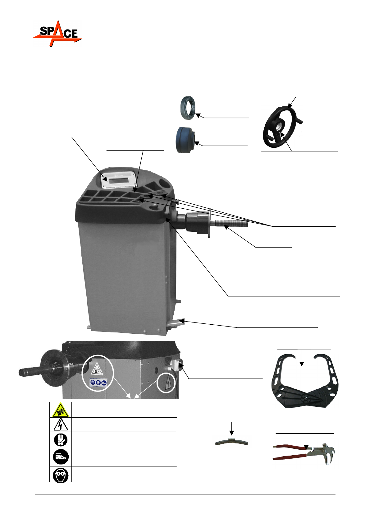
3 COMPOSITION OF EQUIPMENT
3.1 Models ER200 - ER220
PEDAL BRAKE
(MOD. ER200 ONLY)
DISPLAY SCREEN
INTEGRATED IN THE
WEIGHT HOLDER
SHAFT
ROD WITH RULE FOR MEASURING
THE DISTANCE OF THE INSIDE FLANK
OF THE RIM.
(IN INITIAL POSITION)
WEIGHT HOLDER
SMALL, MEDIUM
AND LARGE CONE
WEIGHT PLIERS
GAUGE FOR MEASURING
RIM WIDTH
CALIBRATION
WEIGHT (100g)
MASTER SWITCH (ON REAR
OF WHEEL BALANCER)
LOCKNUT
LEVER FOR QUICK
ENGAGEMENT/DISENGAGEMENT
MOD.ER220 ONLY
PRESSURE
RING
PROTECTION
CAP
INSTRUCTION MANUAL
SPACE s.r.l. ER 200 - ER 220
ER150 - ER160 - ER165
Code M0076 - rev.1.6
(04/2005)
Page 6/ 40 SPACE s.r.l. – 10090 Trana (TO) Via Sangano, 48
Tel. (+39) 011/ 933.88.65 – Fax (+39) 011/ 933.88.64
e-mail: info@spacetest.com
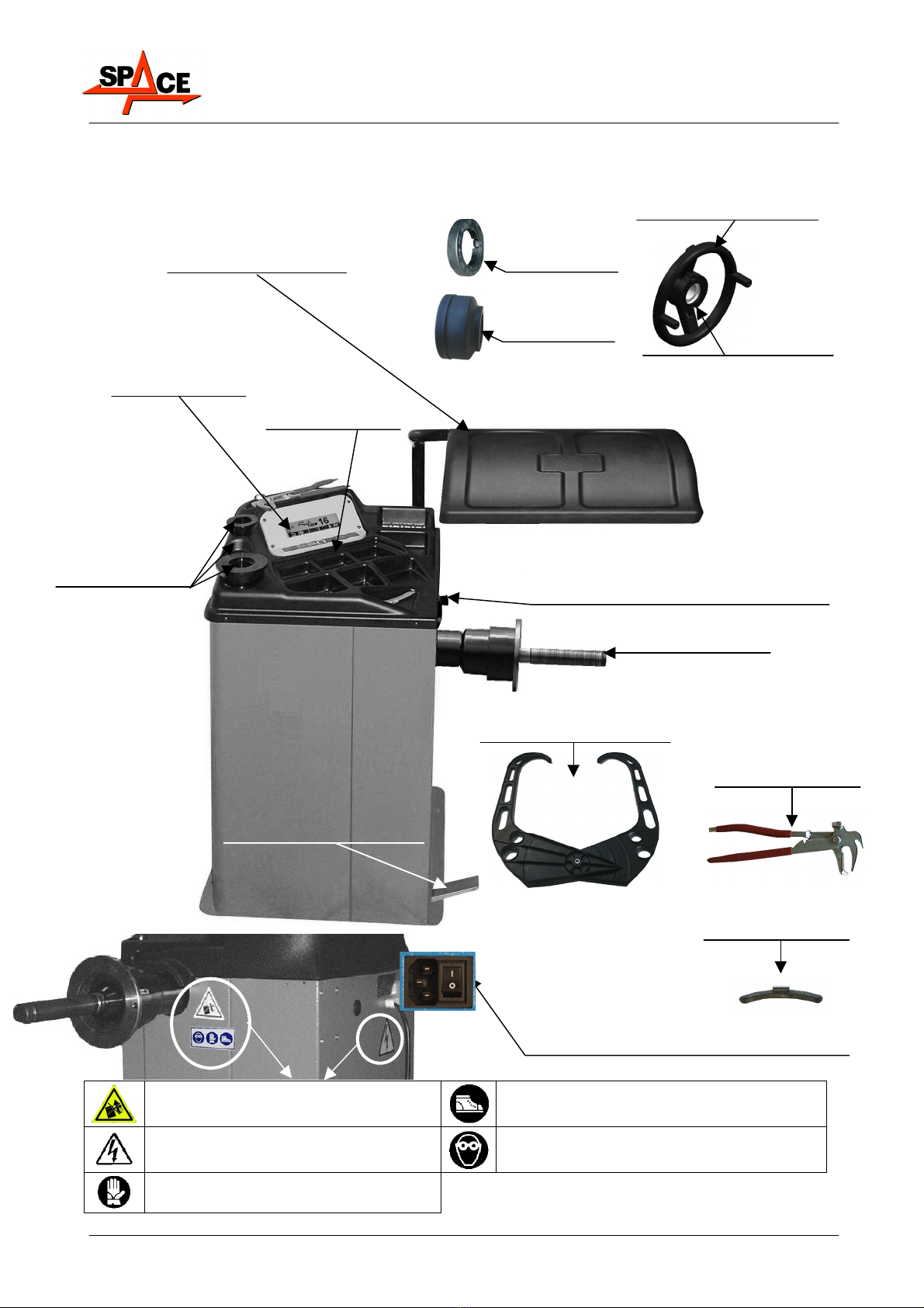
3.2 Models ER150 - ER160 - ER165
PEDALE BRAKE
(MOD. ER150 ONLY)
DISPLAY SCREEN
INTEGRATED IN THE
WEIGHT HOLDER
SHAFT
ROD WITH RULE FOR MEASURING THE
DISTANCE OF THE INSIDE FLANK OF THE RIM
(IN INITIAL POSITION)
WEIGHT HOLDER
SMALL, MEDIUM
AND LARGE CONE
PROTECTION
GUARD (RAISED)
ON MOD. ER165 ONLY
WEIGHT PLIERS
LOCKNUT
LEVER FOR QUICK
ENGAGEMENT/DISENGAGEMENT
MOD.ER160/ ER165 ONLY
PRESSURE
RING
GAUGE FOR MEASURING RIM
WIDTH
CALIBRATION
WEIGHT (100g)
PROTECTION
CAP
MASTER SWITCH (ON REAR OF WHEEL
BALANCER)
Caution: Never lift the machine by means
of the shaft Wear work shoes
Shock hazard Wear work goggles
Wear work gloves

INSTRUCTION MANUAL
SPACE s.r.l. ER 200 - ER 220
ER150 - ER160 - ER165
Code M0076 - rev.1.6
(04/2005)
SPACE s.r.l. – 10090 Trana (TO) Via Sangano, 48 Page 7/ 40
Tel. (+39) 011/ 933.88.65 – Fax (+39) 011/ 933.88.64
e-mail: info@spacetest.com
3.3 Safety devices
The wheel balancer features a number of safety devices. One of these is located on the
rear of the machine (master switch), see chap. 3, page 5. The master switch interrupts
power to the machine when turned clockwise.
In the case of model ER165 it is best to close the protection guard before spinning the wheel.
(key F1 on keyboard) can be pressed if required to manually stop the wheel in
case of an emergency.
3.4 Technical details
ER200
ER150
ER220
ER160 ER165
Max wheel weight 65kg 65kg 65kg
Max power absorption 40W 100W 100W
Power supply 230V 50/60Hz 1ph 230V 50/60Hz 1ph 230V 50/60Hz 1ph
Balancing precision ± 1g ± 1g ± 1g
Balancing speed 99 rpm 99 rpm 99 rpm
Min/max rim - machine distance 0÷400mm 0÷400mm 0÷400mm
Rim width setting 1.5” ÷ 22” 1.5” ÷ 22” 1.5” ÷ 22”
Diameter setting 10” ÷ 24” 10” ÷ 24” 10” ÷ 24”
Max wheel diameter inside protection --1016mm
Max wheel width inside protection --560mm
Sound emission level < 70 dB < 70 dB < 70 dB
Cycle time 7 sec 7 sec 7 sec
Weight 78kg (ER200)
68kg (ER150)
82kg (ER220)
72kg (ER160) 80kg (ER165)

INSTRUCTION MANUAL
SPACE s.r.l. ER 200 - ER 220
ER150 - ER160 - ER165
Code M0076 - rev.1.6
(04/2005)
Page 8/ 40 SPACE s.r.l. – 10090 Trana (TO) Via Sangano, 48
Tel. (+39) 011/ 933.88.65 – Fax (+39) 011/ 933.88.64
e-mail: info@spacetest.com
3.5 Overall dimensions
3.5.1 Models ER200 - ER220
3.5.2 Models ER150 - ER160 - ER165

INSTRUCTION MANUAL
SPACE s.r.l. ER 200 - ER 220
ER150 - ER160 - ER165
Code M0076 - rev.1.6
(04/2005)
SPACE s.r.l. – 10090 Trana (TO) Via Sangano, 48 Page 9/ 40
Tel. (+39) 011/ 933.88.65 – Fax (+39) 011/ 933.88.64
e-mail: info@spacetest.com
4 TRANSPORT AND INSTALLATION
4.1 Transport and unpacking
The machine is supplied packed in a box fastened to a pallet to facilitate
transport. To transport the machine to the point where it is to be installed, use a
lifting and transport mechanism such as a fork-lift truck or lift with forks.
The lifting device must have a lifting capacity equal at least to the weight of the
packed machine. During transport, prevent the lifted machine from swinging.
The machine must be stored in its packaging, in a dry and ventilated
environment (with a temperature between -25° +55°C).
Never overturn or position the packaging horizontally. The pallet must always
rest on a flat and solid surface. Do not stack other packages on top of the
packaging. Always position so the instructions can be easily read.
DURING UNPACKING, ALWAYS WEAR GLOVES TO PREVENT ANY INJURY
CAUSED BY CONTACT WITH PACKAGING MATERIAL (NAILS, ETC.).
Make sure you have received all standard parts as previously listed.
The packaging material (plastic bags, polystyrene, nails, screws, wood, etc.) must
be collected up and disposed of through authorised channels, except for the
pallet, which could be used again for subsequent machine handling.
4.2 Installation
Position the wheel balancer where this is to be used. Never lift the machine by
means of the shaft.
Install the machine in a dry, covered and well-lit place, possibly closed or
protected against the elements. Before positioning the machine, make sure the
place chosen complies with applicable safety regulations and check the
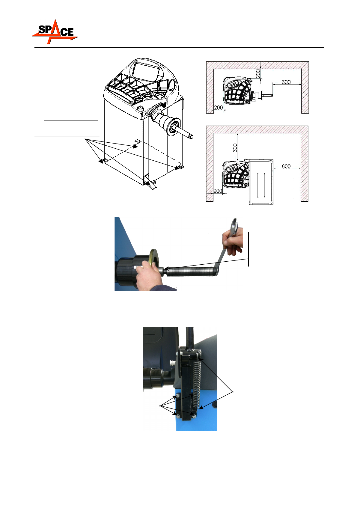
minimum distances from walls or other obstacles (see Figure 1).
The position must be such as to allow the operator to see the area around the
machine. During operation in fact, the operator must make sure there is no one
or nothing in the vicinity of the machine that could represent a hazard.
The characteristics of the machine operating environment must be maintained
within the following limits:
- temperature: 0° + 45° C ; relative humidity: 30 ÷ 90 % (without dew);
The wheel balancer can operate on any solid and flat surface.
Make sure the 4 support points are resting properly on the floor and if necessary
shim.
The machine is best secured to the floor at the 4 above anchor points (Figure 1).
Anchoring is mandatory if wheels weighing more than 30 kg are used; use floor
anchors for M8 x 80 mm screws.
• drill 4 x 10 mm dia. holes opposite the holes in the page;
• fit the anchors and install the machine so this coincides with the holes made
and then tighten the screws (torque wrench setting: about 22 Nm).
INSTRUCTION MANUAL
SPACE s.r.l. ER 200 - ER 220
ER150 - ER160 - ER165
Code M0076 - rev.1.6
(04/2005)
Page 10/ 40 SPACE s.r.l. – 10090 Trana (TO) Via Sangano, 48
Tel. (+39) 011/ 933.88.65 – Fax (+39) 011/ 933.88.64
e-mail: info@spacetest.com
Figure 1
4.2.1 Fitting the shaft on the flange
Figure 2
4.2.2 Fitting the protection guard (mod. ER165 only)
Figure 3
Fasten the shaft on the
flange using a setscrew
wrench
Check this is touching at the 4
support points provided.
Add shims as required;
Anchor if wheels are used
weighing > a 30kg
cTighten the 4 screws
sustaining the guard support
in the special inserts
positioned in the rear of the
unit using a socket wrench
dfit the spring between
the base of the support
and the anchor pin
MEASUREMENTS IN MILLIMETRES
ER200
ER220
ER150
ER160
ER165

INSTRUCTION MANUAL
SPACE s.r.l. ER 200 - ER 220
ER150 - ER160 - ER165
Code M0076 - rev.1.6
(04/2005)
SPACE s.r.l. – 10090 Trana (TO) Via Sangano, 48 Page 11/ 40
Tel. (+39) 011/ 933.88.65 – Fax (+39) 011/ 933.88.64
e-mail: info@spacetest.com
4.2.3 Brightness and contrast adjustment
In the first page of the program press the below indicated keys to adjust brightness and
contrast. Such adjustment is identical for all display. See Figure 4. Try to find the best
settings, going across the all steps, because the settings can pass through clear, dark and
again clear.
NOTE: The settings done remains also after a shut-down.
Figure 4
4.2.4 Power connections
Before connecting up the machine, carefully check:
• power line specifications correspond to machine requirements as shown on the machine
plate;
• there is an earth lead and this is of suitable size (section greater or same as max section of
the power cables).
•that all the component parts of the power line are in good condition;
•that a wall switch exists solely for starting and stopping the machine. This must feature a
residual current and thermal magnetic circuit breaker, taking into account the electrical
power indicated on the wheel balancer.
Connect the machine up to the mains by means of the 3-pole plug provided (230 V single-
phase) through the wall socket.
If the plug provided is not suitable for the wall socket, fit a plug that complies with local and
applicable regulations. This operation must be performed by expert and professional
personnel.
Press repeatedly to
obtain more
brightness/contrast
Press repeatedly to
obtain less
brightness/contrast
Keep it pressed

INSTRUCTION MANUAL
SPACE s.r.l. ER 200 - ER 220
ER150 - ER160 - ER165
Code M0076 - rev.1.6
(04/2005)
Page 12/ 40 SPACE s.r.l. – 10090 Trana (TO) Via Sangano, 48
Tel. (+39) 011/ 933.88.65 – Fax (+39) 011/ 933.88.64
e-mail: info@spacetest.com
5 FITTING THE WHEEL ON THE SHAFT
To achieve perfect balancing, the wheel must be carefully and properly fitted on the shaft.
Imperfect centring will inevitably cause unbalances.
Most important is that original cones and accessories are used. made specifically for
use on the wheel balancer.
Wheel fitting using the cones provided is illustrated below.
For alternative fittings, using optional accessories, refer to the special instructions provided
separately.
1. Remove any type of
foreign body from the
wheel: already-existing
weights, stones and
mud, and make sure
the shaft and the rim
centring area are clean
before fitting the wheel
on the shaft.
2. Carefully choose the cone
most suitable for the wheel to
be balanced. These
accessories must be
selected according to the
shape of the rim.
Carefully position the wheel
using the cone (otherwise
this could seize) until this
rests against the support
flange.
3. Fit the wheel
with the inner
side of the rim
towards the
wheel balancer
and against the
cone.
STANDARD WHEEL
4. Fit the protection
casing in the
locknut and
fasten against the
wheel.
Some aluminium wheels, with very high centring, must be fitted with the cone outside the
wheel.
1. Clean the shaft before
fitting the wheel.
2. Fit the wheel with the
outside of the rim
towards the wheel
balancer, until the wheel
is up against the support
flange.
3. Fit the cone with
the narrowest
part turned
towards the
wheel
4. Fit the grip-ring in the
locknut and secure
the cone.
ALUMINIUM WHEEL WHEEL FITTING
CONE PRESSURE
RING
LOCKNUT
SHAFT
SHAFT
WHEEL FITTING CONE
LOCKNUT
PROTECTION
CAP

INSTRUCTION MANUAL
SPACE s.r.l. ER 200 - ER 220
ER150 - ER160 - ER165
Code M0076 - rev.1.6
(04/2005)
SPACE s.r.l. – 10090 Trana (TO) Via Sangano, 48 Page 13/ 40
Tel. (+39) 011/ 933.88.65 – Fax (+39) 011/ 933.88.64
e-mail: info@spacetest.com
6 SWITCHING THE MACHINE ON AND OFF
The ON/OFF master switch is located on the rear of the machine.
To start the machine and access the program, switch on the system by turning the master
switch to ON (I).
Wait a few seconds for the operating program to load and for the first program page to appear
on the display screen.
The monitor shows various types of information and presents the user with numerous
operation options.
Figure 5
ICON KEY DESCRIPTION
RED (F1) Displays the program configuration panel
YELLOW (F2) Displays the alu correction procedures.
/CENTRE Displays car or motorcycle mode
BLUE (F3) Displays the tests of the different services (4 different
services are managed) para. 7.2 on page 18
GREEN (F4) The dynamic balancing test starts
By means of the 5 keys located on the display mask (F1-F2-CENTRE-F3-F4) all the machine
functions can be used.
During program running, the various display pages show the different keys by means of
which the corresponding function can be immediately selected.
Many display pages contain several rows of keys. In this case, the next row of keys can be
displayed by means of the key corresponding to the icon .
To go back and display the previous row of keys, press the key corresponding to the icon
or in some cases .
Program
operation key
FIRST
PAGE

INSTRUCTION MANUAL
SPACE s.r.l. ER 200 - ER 220
ER150 - ER160 - ER165
Code M0076 - rev.1.6
(04/2005)
Page 14/ 40 SPACE s.r.l. – 10090 Trana (TO) Via Sangano, 48
Tel. (+39) 011/ 933.88.65 – Fax (+39) 011/ 933.88.64
e-mail: info@spacetest.com
7 WHEEL BALANCING
7.1 Determination of wheel dimensions
7.1.1 Manual setting of wheel dimensions for dynamic balancing and ALU 1, 2, 3, 4
functions
SPACE wheel balancers feature a manual gauge and a graduated scale for determining wheel
dimensions (Figure 7 and Figure 8).
The rim distance dimension is always set with "mm" unit of measurement.
The width and diameter dimensions on the other hand can be set in "inches" or "mm". The
examples shown in this manual show measurements in "inches". To change the unit of
measurement from "inches" to "mm", see chap. 11 on page 34.
Figure 6
ICON KEY DESCRIPTION
RED (F1) Return to display previous page
YELLOW (F2) Decrease wheel dimension values
CENTRE Select and confirm the value to be set
BLUE (F3) Increase wheel dimension values
GREEN (F4) Perform spin
Press centre key ( ) to select the value to be set.
The display screen will show the selected value on black background and on the right the
same value in large characters (Figure 6).
Manually set the width. Generally speaking, the nominal width is indicated on the rim, but it
is always a good idea to position the graduated scale on the inner and outer side of the wheel
as shown in Figure 7 and determine the measurement to be set.
To enter the wheel width, the operator must select the “PLUS” or “MINUS” key
until the desired width is achieved.
Figure 7
Rim distance
value
Rim diameter
Selected dimension
displayed enlarged
User no. in use
Selected
program
Rim width (selected
d
im
e
n
s
i
o
n
)
MANUAL
GAUGE

INSTRUCTION MANUAL
SPACE s.r.l. ER 200 - ER 220
ER150 - ER160 - ER165
Code M0076 - rev.1.6
(04/2005)
SPACE s.r.l. – 10090 Trana (TO) Via Sangano, 48 Page 15/ 40
Tel. (+39) 011/ 933.88.65 – Fax (+39) 011/ 933.88.64
e-mail: info@spacetest.com
Press the centre key ( ) to select the rim diameter dimension.
Enter the rim diameter by selecting the “PLUS” or “MINUS” key until the desired
value is achieved.
Press the centre key ( ) to select the rim distance dimension
Move the graduated scale from the initial position against the inner edge to measurement
position (see Figure 8). Read the value to be set on the rule.
Enter the rim distance by selecting the “PLUS” or “MINUS” key until the desired
value is achieved.
Figure 8
After setting all the wheel dimensions, press the centre key ( ) again to confirm. The
program will show the page in Figure 9.
Figure 9
ICON KEY DESCRIPTION
RED (F1) Return to display previous page
YELLOW (F2) User management (para. 7.2 on page 18)
CENTRE Select and confirm the value to be set
BLUE (F3) Display the next row of keys
GREEN (F4) Perform spin
MANUAL
GRADUATED
SCALE IN
MEASUREMENT
POSITION
Dimensions entered
and confirmed

INSTRUCTION MANUAL
SPACE s.r.l. ER 200 - ER 220
ER150 - ER160 - ER165
Code M0076 - rev.1.6
(04/2005)
Page 16/ 40 SPACE s.r.l. – 10090 Trana (TO) Via Sangano, 48
Tel. (+39) 011/ 933.88.65 – Fax (+39) 011/ 933.88.64
e-mail: info@spacetest.com
7.1.2 Wheel dimension manual setting for ALU-S type correction
Select the ALU-S function as described in para. 7.4 on page 22 and press the “CENTRE key”
to confirm and enter the measurements.
The display screen will show the page in Figure 10.
Move the graduated scale to the position where the inner weight is to be fitted. Read the
value to be set on the scale. Enter the distance by selecting the “PLUS” or “MINUS”
key until the desired value is achieved.
Press the “CENTRE key” to confirm.
Figure 10
The "acquired dimension" indication is given by the first measurement point indication arrow,
which goes from white to black.
Figure 11
Move the graduated scale to the position where the outer weight is to be fitted (always hidden
inside the rim). Read the value to be set on the scale. Enter the distance by selecting the
“PLUS” or “MINUS” key until the desired value is achieved.
Press the “CENTRE key” to confirm.
Figure 12

INSTRUCTION MANUAL
SPACE s.r.l. ER 200 - ER 220
ER150 - ER160 - ER165
Code M0076 - rev.1.6
(04/2005)
SPACE s.r.l. – 10090 Trana (TO) Via Sangano, 48 Page 17/ 40
Tel. (+39) 011/ 933.88.65 – Fax (+39) 011/ 933.88.64
e-mail: info@spacetest.com
The "acquired dimension" indication is given by the second measurement point indication
arrow, which goes from white to black.
Enter the wheel diameter (Figure 12) by selecting the “PLUS” or “MINUS” key
until the desired value is achieved. Press the "CENTRE key" to confirm.
The program will show the page in Figure 13.
Figure 13
To display all the measurements entered, press the "CENTRE key" several times.
Press the “F4 key” to start the spin.
7.1.3 Manual setting of wheel dimensions for static correction
Select the STATIC function as described in para. 7.4 on page 22 and press the "CENTRE key"
to confirm and enter the measurements.
The display screen shows Figure 14.
Move the graduated scale to the position where the weight is to be fitted. Read the value to be
set on the scale. Enter the distance by selecting the “PLUS” or “MINUS” key
until the desired value is achieved.
Press the “CENTRE key” to confirm.
Figure 14
The "dimension acquired" indication is shown by the measurement point indication arrow
which goes from white to black.
Figure 15
Dimensions
entered and
confirmed

INSTRUCTION MANUAL
SPACE s.r.l. ER 200 - ER 220
ER150 - ER160 - ER165
Code M0076 - rev.1.6
(04/2005)
Page 18/ 40 SPACE s.r.l. – 10090 Trana (TO) Via Sangano, 48
Tel. (+39) 011/ 933.88.65 – Fax (+39) 011/ 933.88.64
e-mail: info@spacetest.com
Enter the wheel width diameter (Figure 15), always selecting the “PLUS” or “MINUS”
key until the desired value is achieved.
Press the “CENTRE key” to confirm.
The display screen will show Figure 16.
Figure 16
To display all the entered measurements, press the "CENTRE key" several times.
Press the “F4 key” to start the spin.
7.2 User management
To select user management, select the following key on the presentation page (para. 6 on
page 13).
SPACE wheel balancers can be used by 4 different users at the same time, by selecting the
above indicated key several times, until the desired user is reached.
When the user key is pressed, the current user number appears on the display screen (U1,
U2, U3 and U4 in car mode or M1, M2, M3 and M4 in motorcycle mode).
The system stores the data relating to the last performed spin according to the different
operators. The desired user can be called every time the program displays the specific key.
The measurements stored for each user are lost when the machine is switched off.
User management is valid for any wheel balancer function.
IMPORTANT: To enable or disable the "User Control" function, see para. 11(Figure 44 on page
35). Once this function has been disengaged by pressing the "User key F3" on the
presentation page (para. 6 on page 13) on the top left of the monitor, the only used user
appears “U” in car mode or “M” in motorcycle mode.
Dimensions
entered and
confirmed
This manual suits for next models
4
Table of contents


