10-Push button, imbalance display pitch and threshold 11- Push button, optimization of
imbalance and split imbalance 12-Counter weights installation posotion diagram.
13-Inside balance weight position light
14-Outside balance weight position light
15-Display the tire medial imbalance values or distance values 16-Display static imbalance value or
width value
17-Display the tire lateral imbalance value or diameter values
N.B. Only use the fingers to press push buttons. Never use the counterweight pincers or other
pointed objects.
6 Installation and Demounting of the Wheel
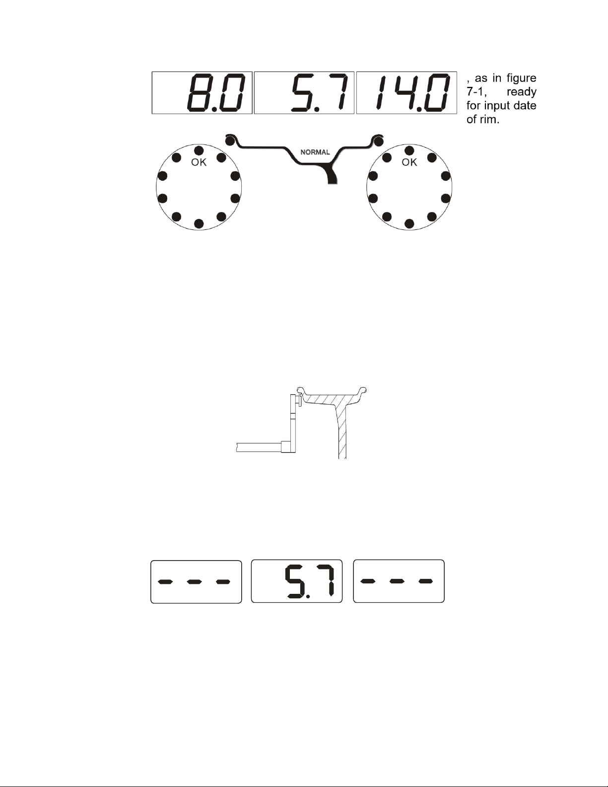
6.1 Checking the wheel
The wheel must be clean, none sand or dust on it, and remove all the primal counterweights
of the wheel. Check the tyre pressure whether up to the rated value. Check positioning plane of
rim and mounting holes whether deformed.
6.2 Installing the wheel
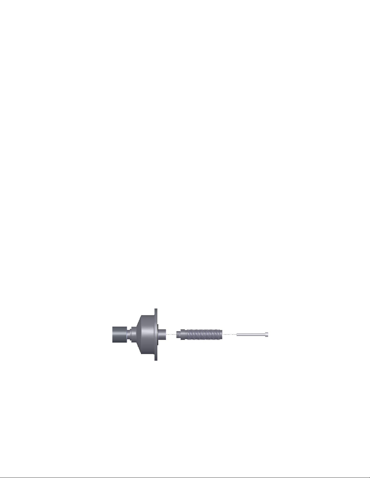
6.2.1 Select the optimal cone for the center hole when there is center hole on the rim.
6.2.2 Two ways of installing the wheel: A. positive positioning; B. negative positioning.
6.2.2.1 Positive positioning (refer to figure 6-1):
Positive positioning is commonly used. It operates easily, and it is applicable for
various rims of common steel structure and thin duralumin structure.
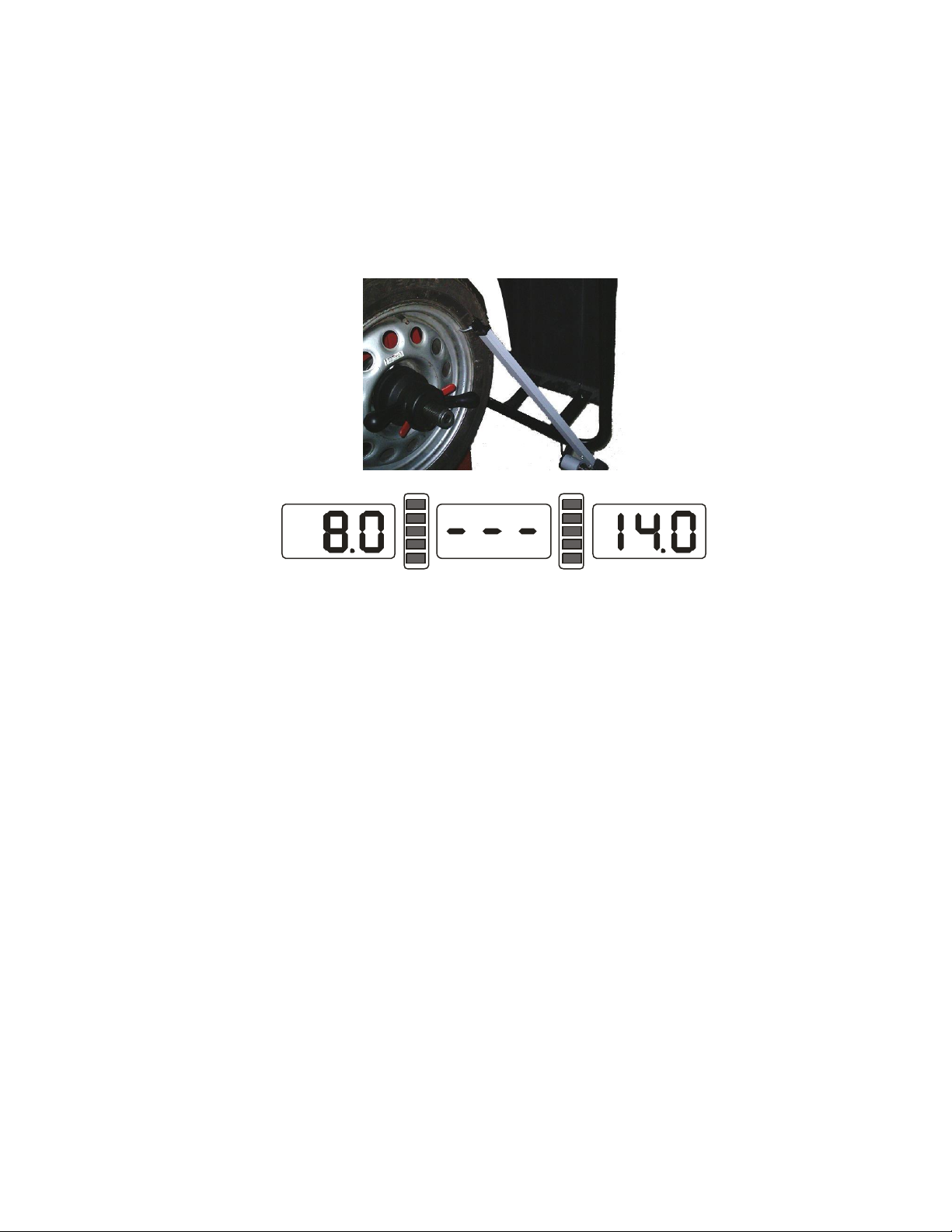
6.2.2.2 Negative positioning (refer to figure 6-2):
Negative positioning is used to ensure the inner hole of steel rim and main shaft is
positioning accurately when the outside of wheel deforming. Apply for all the steel rims,
thick steel rims especially.