Spacetronik SP-IPL07AHD User manual
IP camera tester
USER MANUAL
(IPC1.03)
SP-IPL07AHD
SP-IPL07SDI

Thank you for purchasing the CCTV security tester. Please read the manual before using the
CCTV tester and use properly.
For using the CCTV tester safely, please first read the「
Safety Information 」
carefully in the
manual.
The manual should be kept well in case of reference.
eep the S/N label for after-sale service within warranty period. Product without S/N label will
be charged for repair service.
If there is any question or problem while using the CCTV tester, or damages occurred on the
product, please contact our technical Department.

Content
1 .Safety information................................................................................................................................ 1
2. IP camera tester Introduction................................................................................................................ 2
2.1 General........................................................................................................................................ 2
2.2 Features....................................................................................................................................... 2
2.3 Function...................................................................................................................................... 4
2.3.6 Enhanced Color bar generator..................................................................................................4
2.3.7 DC12V 2A/DC 5V 2A output power.......................................................................................6
2.3.8 Audio testing............................................................................................................................ 6
2.3.9 Cable tester............................................................................................................................... 6
2.3.10 PTZ data analysis...................................................................................................................6
2.3.12 Video screenshot, record and playback..................................................................................6
2.3.13 DHCP dynamic address assignment.......................................................................................6
2.3.14 the dynamic address accessed................................................................................................ 7
2.3.15 Multi- segment IP Camera Test..............................................................................................7
2.3.25 WIFI....................................................................................................................................... 8
2.3.26 SDI came test (*only in SDI model).................................................................................8
2.3.27 PoE power supply.................................................................................................................. 8
2.3.28 HDMI signal output...............................................................................................................9
2.3.29 Network bandwidth testing.................................................................................................... 9
2.3.30 Cable search (Optional).......................................................................................................... 9


3.2.1 IP camera connection............................................................................................................. 15
3.2.2 Analog camera test...............................................................................................................16
3.3 OSD menu................................................................................................................................. 16
3.3.1Video monitor test........................................................................................................... 19
3.3.2 Color-bar generator (TV OUT)......................................................................................27
3.3.3 ONVIF...........................................................................................................................28
3.3.4 IP camera test................................................................................................................. 36
3.3.5 IP address scan............................................................................................................... 38
3.3.6 PING test........................................................................................................................ 39
3.3.7 Cable test........................................................................................................................ 40
3.3.8 Cable scan......................................................................................................................40
3.3.9 Port flash........................................................................................................................ 42
3.3.10 Data monitor................................................................................................................. 43
3.3.11 Optical power meter (Optional ).............................................................................43
3.3.12 Visual Fault Locator(optional)................................................................................45
3.3.13 Digital Multi-meter (optional )................................................................................47
3.3.14 Video Player................................................................................................................. 54
3.3.15 Music player................................................................................................................. 55
3.3.16 LED lamp (Flashlight)..................................................................................................56
3.3.17 PoE test........................................................................................................................57
3.3.18 TDR cable test (optional).......................................................................................57
3.3.19 Calculator..................................................................................................................... 60
3.3.20 Browser........................................................................................................................ 61
3.3.21 IPC viewer....................................................................................................................61
3.3.22 DC12V power output, PoE power supply....................................................................63
3.3.23 Application tools.......................................................................................................... 64
3.3.24 APPS Tools..................................................................................................................71
3.3.25 System Set.................................................................................................................... 72

3.3.26 Update.......................................................................................................................... 73
3.4 Audio test.................................................................................................................................. 74
3.5 HDMI output............................................................................................................................. 74
3.6 PoE power................................................................................................................................. 74
3.7 DC12V 2A power output..........................................................................................................75
3.7 USB 5V 2A power output.........................................................................................................76
4. Specifications.............................................................................................................................. 77
4.1 General Specifications...............................................................................................................77
4.2 Multi-meter specifications......................................................................................................... 79
4.3 Optical power meter specifications........................................................................................... 81
4.4 Visual fault locator specifications.............................................................................................82
AHD Model can measure AHD camera's
and SDI Model can measure SDI camera's.

1 .Safety information
◆The tester is intended to use in compliance with the local rules of the electrical usage and avoid to
apply at the places which are inapplicable for the use of electrics such as hospital, gas station etc.
◆To prevent the functional decline or failure, the product should not be sprinkled or damped.
◆The exposed part of the tester should not be touched by the dust and liquid.
◆During transportation and use, it is highly recommended to avoid the violent collision and vibration
of the tester, lest damaging components and causing failure.
◆Don’t leave the tester alone while charging and recharging. If the battery is found severely hot, the
tester should be powered off from the electric source at once. The tester should not be charged over 8
hours.
◆Don’t use the tester where the humidity is high. Once the tester is damp, power off immediately and
move away other connected cables.
◆The tester should not be used in the environment with the flammable gas.
◆Do not disassemble the instrument since no component inside can be repaired by the user. If the
disassembly is necessary indeed, please contact with the technician of our company.
◆The instrument should not be used under the environment with strong electromagnetic interference.
◆Don’t touch the tester with wet hands or waterish things.
◆Don’t use the detergent to clean and the dry cloth is suggested to use. If the dirt is not easy to
remove, the soft cloth with water or neutral detergent can be used. But the cloth should be tweaked
sufficiently.
About Digital Multi-meter
◆Before using, you must select the right input jack, function and range.
◆Never exceed the protection limit values indicated in specifications for each range of measurement.
◆When the meter is linked to a measurement circuit, do not touch unused terminals.
◆Do not measure voltage if the voltage on the terminals exceeds 660V above earth ground.
◆At the manual range, when the value scale to be measured is unknown beforehand, set the range
selector at the highest position.
◆Always be careful when working with voltages above 60V DC or 40V AC, keep fingers behind the
Page.1.

probe barriers while measuring.
◆Never connect the meter with any voltage source while the function switch is in the current,
resistance, capacitance, diode, continuity, otherwise it will damage the meter.
◆Never perform capacitance measurements unless the capacitor to be measured has been discharged
fully.
◆Never measure any of resistance, capacitance, diode or continuity measurements on live circuits.
Visual laser sour es
When you turn on visual laser sources, please don’t stare at it, or will damage to eyes
When not using it,Please turn it off and cover the protective cap .
2. IP amera tester Introdu tion
2.1 General
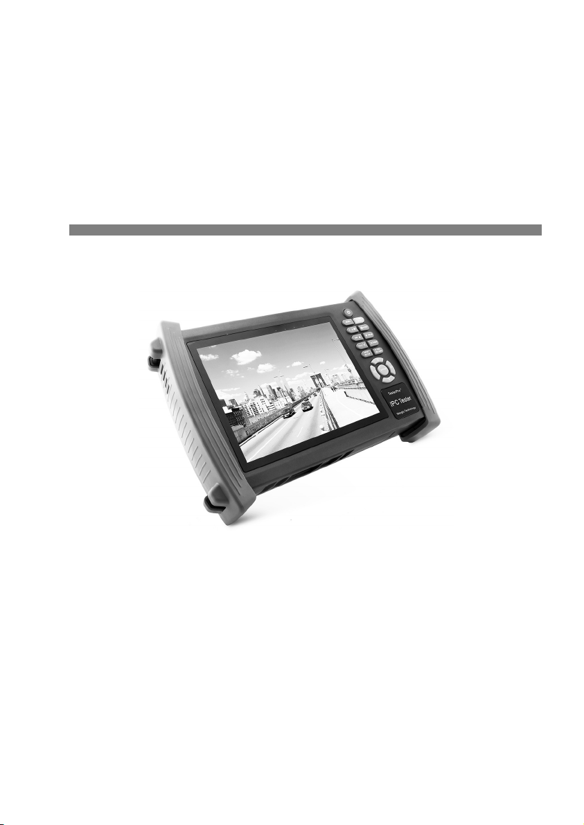
7 inch Touch Screen IPC camera tester is for maintenance and installation of IP camera and Analogue
camera ,display HD camera and analogue camera image ,PTZ control, easy to use and operate .
Built in network testing tools (IP address search, PING etc), quickly check the IP camera problem.
Cable scan, TDR tester, easy to check the network cable, BNC cable problem. Optical power meter,
Visual fault detector function, effective to solve the optical fiber transmission problem.
2.2 Features
7 inch 800×600 touch screen, easy to operate
Support ONVIF came test
Support Dahua,HI VISION,ACTI ,H.264/MPEG4/MJPEG camera test etc( Customize)
Built in Wi-Fi ,can receive wireless camera(ONVIF and customize camera)
SDI Digital camera image display, record and screenshots * (Optional)
HDMI signal input,support1080P*(Optional)
HDMI signal output,support1080P
Analogue video image display, Auto adapt and display the video format of NTSC/PAL
Page.2.

Support more than 30 protocols ,such as PELCO-P、PELCO-D、SAMSUNG etc
Video image magnification, to view the details, easy to use
Snapshot and save the current image as JPG file in the SD card, video record and playback
LED Lamp, easy to operate at night
Micro SD card moveable
LCD screen brightness/contrast/color Saturation adjustable
Visual fault locator , to test fiber’s bending and breakage(Optional)
Optical power meter ,test fiber loss and value
Digital Multi-meter , DC and AC voltage measurement, Resistance measurement,
Continuity test, Diode measurements, Capacitance measurement(Optional)
Enhanced Color bar generator, Video Generating, the PAL/NTSC multi-system color bar video
generator (Eight-system switchable, transmit/receive eight-system colorful imagines).
PEA video signal level, SYNC signal level, COLOR BURST chroma level measurement,test
video signal attenuation (Optional)
Cable scan, Send the specific signal, easy to find the connected cable.
PING is the most conventional network debugging tools; It is used for testing if the connected IP
camera or other network equipment’s Ethernet port is working normally and the IP address is
correct.
In digital IP surveillance applications, if IP camera’s IP address is not clear or forgotten; the
device cannot be used .IP address scan can quickly search the connected IP camera or other
network device’s IP address.
PoE voltage test,It can test the PoE voltage when the POE switch is supplying the POE power
to IP camera ,wireless AP etc
TDR cable test,test cable length and short-circuit (Optional)
Cable test , Test LAN cable or telephone cable,UTP cable etc ,cable type and the sequence of
wires will be displayed
Support RS232/RS485,Rate 600 ~ 115200bps adjustable
PTZ protocol analysis, control protocol command displays to check RS485 transmission
Page.3.

Whether is normal, easy to find the fault device
PTZ control. Pan/tilts the P/T unit, zooms in/out the lens, adjusts the focus, aperture and
sets and the preset position
DC12V 2A output power for camera
PoE power output,supply temporary power for PoE camera
DC5V 2A power output,as a power bank
Audio input test, test the audio signal from pickup devices
7.4V 48.1Wh Battery energy display, It can last 16hours for normal use after charging for 8
hours
2.3 Fun tion
2.3.1 Tou h s reen and OSD menu
IPC camera tester use capacitive touch screen operation,easy to use and improve work efficiency.
The function icons can move to APPS tool file and menu, the common function keep on the main menu,
the others be move to Apps tool file, the menu more clearly.
2.3.2 IP amera test
Built in ONVIF test, IP camera tester, browser function etc, display IP camera image and change IP
address. 7 inch 800×600 screen display,Larger viewing angle, it convenient engineers to locate the
network camera. Built in ONVIF TOOLS and PTZ control, IP camera protocols customized ,support
test more than 30 IP camera types now ,such as ACTi、
Dahua IPC-HFW2100P、
Hikvision,DS-2CD864-
E13、
Samsung SNZ-5200、
Tiandy TD-NC9200S2、
odak IPC120L、
Honeywell HICC-2300T、
Aipu-
waton IP5000-BC-13MP/IRS06-13MP、fine-Tida IPC、FSJ BY-1080Q、WEIS Y IPC camera etc.
2.3.3 Analog amera test
Display analog camera image ,7 inch 800×600 LCD screen display ,larger viewing angle ,More
intuitively and easily display the camera image quality. Support PAL/NTSC format image signal .
LCD screen backlight brightness adjustable, and analog video image brightness/contrast/color
Saturation adjustable.
Page.4.

2.3.4 Video level meter
PEA video signal level, SYNC signal level, COLOR BURST chroma level measurement
Use hardware high-frequency sampling and processing technology; test the Peak video signal, SYNC
signal level, COLOR BURST chroma level more accurate.
PEA video signal level: Measuring peak video signal, the video signal level is 1000±175mV in PAL
format (NTSC format :140±15IRE ), the level is too low will cause the image to dim, reducing dynamic
range; Level is too high will lead to virtual shadow, reducing the definition of the image .
The SYNC signal level: measuring the amplitude of the video sync pulse, for determining the video
level is correct and that the coaxial cable connectivity. Sync level range is 300 ± 35mV in PAL
format(NTSC format: 40 ± 5IRE ), the level is too low will cause the image to fracture or scroll; Level
is too high will reduce the image color levels and dynamic range.
COLOR BURST chroma level: Measuring camera color burst level, to determine whether the coaxial
cable transmission for the best detail and color. Chroma standard level is 280mV in PAL format and is
40 IRE in NTSC format. Chroma level is low,Chroma level is low, the color will become dark, color
level is too low, the details of monitor reception image will be lost and even become black and white;
chroma level is too high, the image will be displayed spot , affect the image detail and clarity. Coaxial
cable is too long will reduce the chroma level.
2.3.5 PTZ ontroller
Display the input video images. Pan/tilt the P/T unit and zoom in/ out the image. Setup the controlling
parameters like protocol, communication port, baud rate, PTZ ID, pan/tilt speed; set and call preset
position.
2.3.6 Enhan ed Color bar generator
Video Generating, the PAL/NTSC multi-system color bar video generator (Eight-system switchable,
transmit/receive eight-system colorful imagines). By receiving the video color bar to test the video
channel whether transmit normally. And judge whether the color is different, because of the
transmission loss or interference, it suitable for Video transmission of the field tests, such as optical
video transmitter and receiver, video cable etc.
Page.5.

The new function color bar can test the image whether shift.
The color bar (red, green, blue, white, black) test the monitor whether have white or black dot etc.
2.3.7 DC12V 2A/DC 5V 2A output power
Power the camera with DC12V (1A) power output from the tester. It is helpful for demo and testing
when the power supply is not available. Built in DC5V2A power output,as a power bank .
2.3.8 Audio testing
Test the audio input from pickup devices. Connect the tester and pickup device with the audio cable.
Recording can save.
2.3.9 Cable tester
Test LAN cable or telephone cable.
Connect LAN cable or telephone cable with the CCTV tester and cable tester. And then the connecting
status, cable type and the sequence of wires will be displayed, as well as the serial number of the cable
tester kit.
2.3.10 PTZ data analysis
Search the Control protocol code from Multifunction keyboard or DVR by RS485 /RS232 interface, test
the PTZ control command data whether received anomaly and RS485/RS232 data transmission.
Screen displays 16 hexadecimal codes such as
PELCO-P:A0 00(Add) xx xxxxxx AF xx
PELCO-D:FF 01(Add)xx xxxxxxxx
2.3.11 Image magnifi ation
Set image zoom, can view and display the details .Support ONVIF 、
DaHua、
Hikvision、
ACTi、
Samsung
camera etc.
2.3.12 Video s reenshot, re ord and playba k
Capture the video image and save the current video frames as JPEG file, record and save the current
video in the SD card, video image and record files are saved in the SD card. Storage file directory can
Page.6.

be created according to the date.
2.3.13 DHCP dynami address assignment
Built in DHCP server, dynamic assign address for the IP camera or network device
2.3.14 the dynami address a essed
ester can accessed IP address assignment from DHCP, as the tester’s IP address, so not need manual
set it.
2.3.15 Multi- segment IP Camera Test
Support Multi- segment Static IP address setting,,Can simultaneously test different segments IP
network cameras
2.3.16 IP address s an
In digital IP surveillance applications, if IP camera’s IP address is not clear or forgotten; the device
cannot be used .IP address scan can quickly search the connected IP camera or other network device’s
IP address.
2.3.17 PING Test
PING is the most conventional network debugging tools; It is used for testing if the connected IP
camera or other network equipment’s Ethernet port is working normally and the IP address is correct.
2.3.18 Port Flashing
The tester will send special signals to make the connected POE port flicker at special frequency, which
will enable the installers to easily and quickly find the connected ethernet cable. This function can
prevent mistakenly insertion or disconnection non-corresponding cable to artificially interrupt network
connection.
2.3.19 PoE Test
It can test the PoE voltage when the POE switch is supplying the POE power to IP camera. It can
clearly display the power+ and power- on the Ethernet cable pins, each cable pin’s voltage and the
failure connection of cable pin series numbers.
Page.7.

2.3.20 Digital Multi-meter (Optional)
CCTV Tester built in highly stable and reliable 33/4 digit (6600) digital multi-meter. It is used for the
DC and AC voltage measurement, AC and DC current measurement, Resistance measurement,
Continuity test, Diode measurements, Capacitance measurement, Auto/Manual measuring range
switching, relative value measurement and locking. It is easy operation and professionally accurate.
2.3.21 Visual fault lo ator (Optional)
Visual Fault Locator with 650nm wavelength can emit red laser sources to test multi-mode and single
mode fiber’s bending and breakage, and Continuous light-emitting and 1HZ, 2Hz modulating light
output. It is indispensable tool in fiber project constructing, fiber net-work maintaining, optical
component manufacture and research.
2.3.22 Opti al Power Meter (Optional)
The New tester adopts the most advanced handheld instrument specific integrated chip , achieve ultra-
low power operation, with the 3.5 TFT-LCD High-definition screen display ,five wavelength
calibration points 1625nm,1550nm ,1490nm , 1310nm , 1300nm , 850nm.Linear or nonlinear optical
power display, it can measure the optical power value, and also be used for Relative measurement of
optical fiber link loss. It is necessary tool for fibre-optic communication, cable television system and
security system maintenance.
2.3.23 LED lamp
It is useful for the Engineer to install and maintain security system at night. Press button LED On/Off,
easy operation.
2.3.24 TDR able length and short ir uit measurement (Optional)
TDR cable testing, accurately measure BNC cable, network cable, controls cable’s length and short-
circuits location. It improves working efficiency.
2.3.25 WIFI
Built in WIFI, can receive wireless camera (ONVIF and customize camera) or network data etc.
2.3.26 SDI amera test (only in SDI model)
SDI digital video surveillance testing, support 720P/1080P digital camera image test and video
Page.8.

image zoom, record ,screenshots, Photo viewer and playback .
2.3.27 PoE power supply
Support PoE power supply,High capacity 48.1WhLithium polymer battery, Provides temporary
power for the PoE network camera .
2.3.28 HDMI signal output
With HDMI output port, support 1080P output, record and media files playback
Via connect HDMI port output to HD TV display
2.3.29 Network bandwidth testing
Network channel bandwidth test, need two instruments to test, one as a transmitter, the other as a
receiver, also can install test software in the PC, combine with instrument to test Network
channel bandwidth
2.3.30 Cable sear h (Optional)
Send the specific signal, easy to find the connected cable.
2.3.31 S reen rotation Display
Support screen 180 degree rotations (manual set), the network port will be on the top, to convenient
connect the cable.
2.3.32 AHD camera test (only in AHD model)
AHD video surveillance testing, support 720P/1080P digital camera image test and video image zoom,
record ,screenshots, Photo viewer and playback .
2.4 Pa king list
1). Tester
2). Adapter Polymer Battery(7.4V DC 6500mAh )
5). BNC cable
6). RS485 cable
7).SC,ST connector(Only for optical power meter)
8).Multi-meter test leads one pair of red and black (only for the Multi-meter models)
9). Output Power cable
Page.9.
10). Audio cable
11). TDR alligator clamp (only for TDR models)
12). Safety cord
13). Tool bag
14). Manual
15) 4G SD card
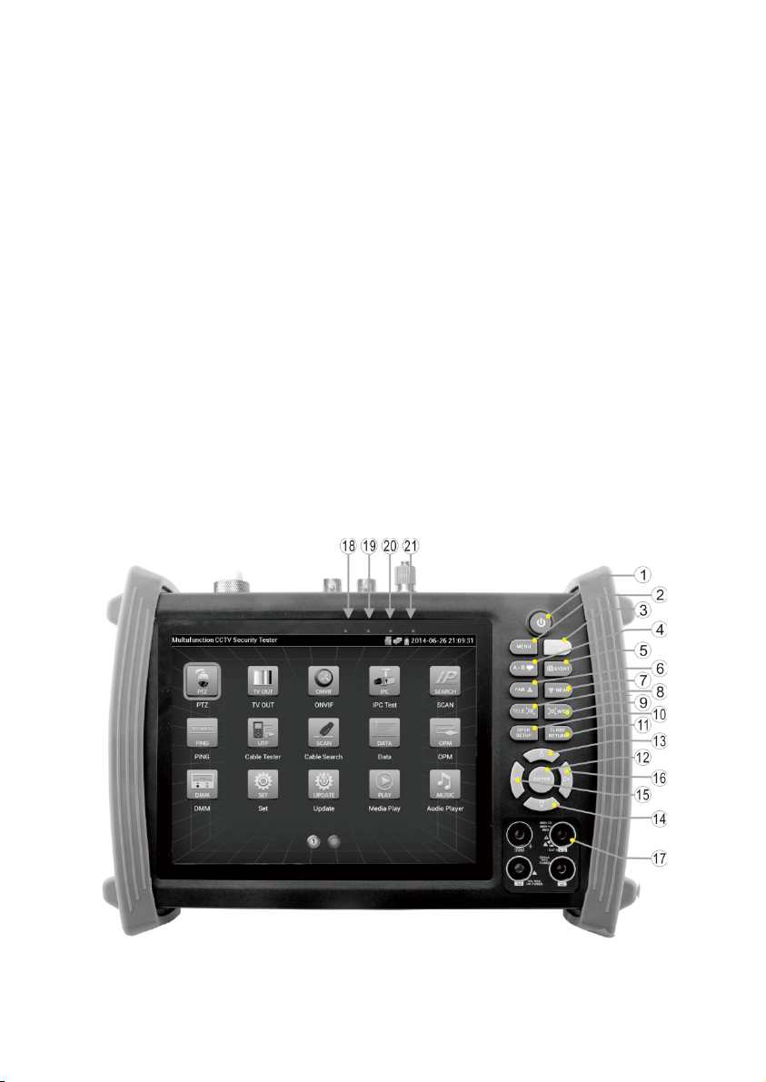
2.5 Fun tion
Page.10.

1 Press more than 2 seconds, turn on or off the device ,short press to turn on or off the
menu display
2Menu key
3
OTDR
test。
10xz
oom the
image
display.
4Video record
5Snapshot
6Far focus: Focus the image faraway
7Near focus: Focus the image nearby
8TELE: zoom in the image
9WIDE: zoom out the image
10 Open/set ,Confirm the setting of parameters, open or enlarge the aperture
11 Return/Close : Return or cancel while setting parameters of the menu, close or
decrease the aperture
12 Confirm key
13 Upward, set function or add parameter. Tilt the PTZ upward
14 Downward, set function or reduce the value of the parameter. Tilt the PTZ
downward
15 Leftward, select the parameter whose value will be changed
16 Rightward, select the parameter whose value will be changed. Add the value of the
parameter. Pan the PTZ right
Page.11.

Top interface
Bottom interface
17 Multimeter interface
18 Battery Charge Indicator,when charging is red, if battery imbue with, charge indicator turn off.
19 RS485/RS232 Data transmission indicator ,red color
20 RS485/RS232 Receive data indicator,red color
21 external power indicator,green
22 Visible red laser source emits Interface((Optional)
Page.12.

23 Output DC12V2A power output , for provisional DC test supply
24 Video image signal input(BNC interface)
25 Video image signal output(BNC interface)/cable search interface
26 Optical power meter interface (Optional)
27 RS485 Interface: RS485communication for the PTZ
28 RS232 Interface: RS232 communication for the PTZ
29 LED lamp
30 TDR cable test interface
31 HDMI output interface
32 Micro SD card moveable,Factory standard card is 4G, largest expansion to 16G
33 UTP cable port: Please use together with UTP LAN cable tester or wire tracker
34 Audio output and earphone interface
35 Audio input
36 PSE power supply input interface
37 PoE power supply output/network test interface,
38 USB 5V 2A power output ,only as a power bank ,not transmit data
39 DC12V2A charging interface
40 Output DC12V2A power output , for provisional DC test supply
Page.13.

3. Operation
3.1 Installing the Battery
The tester has built-in lithium ion polymer rechargeable battery. The battery cable inside battery
cabin should be disconnected for safety during transportation!
Prior to the use of the instrument, the battery cables inside the battery cabin should be well
connected.
Usually it doesn’t need to disconnect the cable at the normal use
Pressing the key continuously can power on or off the tester.
Notice:Pls use the original adaptor and connected cable of the device!
when charging,show the battery is full or Charge Indicator turns off, Indicates that the battery
imbue with.
Notice: When the Charge Indicator turns off, the battery is approximately 90%
charged. The charging time can be extended for about 1 hour and the charging time within 12
hours will not damage the battery.
Noti e :Press the key several seconds to restore the default settings when the
instrument works abnormally.
Multi-meter: the red and black multi-meter pen must insert the corresponding port.
Warnings:Instrument communication port is not permitted access circuit voltage over 6V,
otherwise damage the tester.
Warnings:Not allow insert multi-meter pen in the
Page.14.
This manual suits for next models
1
Table of contents


