Circutor MEG-1000 User manual

INSULATION GUARD
MEG-1000
(Code M15051)
INSTRUCTION MANUAL
(M98122001-20-19A)
(c) CIRCUTOR S.A.

MEG-1000
Page nº 1
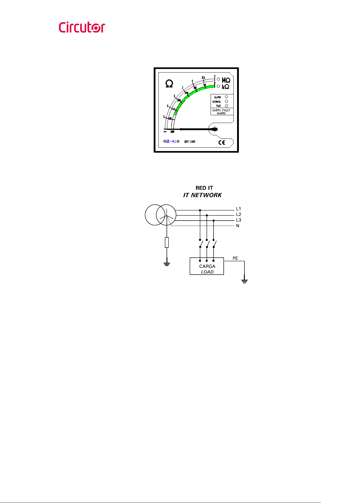
Insulation guard MEG-1000
1.-BASIC INSTRUCTIONS
1.1.- Delivery spot check
This manual is issued to help all the MEG-1000 users to install and use it in order
to get the best from it. After receiving the unit please check the following points:
(a) Does this device corresponds to your order specifications?
(b) Check if any damage was done during the shipment process.
(c) Verify that it includes one instruction manual.
1.2.- Connection procedures
For the safe use of MEG-1000 is basic that people who install or handle it follow
the normal safety considerations and the diverse advises related in this manual.
Before connecting verify:
a. The power supply of the instrument (as default, 230 Va.c.
±
20 %)
corresponds to the rated voltage of the mains where you have to power it.
b. The voltage between phase and ground (points between which the insulating
level will be measured) have to be in normal conditions lower or equal than
600 Va.c.
c. Due to its operation mode, the device can only be used in A.C. networks.
MEG-1000
Page nº 2
2.- MAIN CHARACTERISTICS
MEG-1000 is an electronic device that measures the insulating resistance between
the ground and one phase of an insulated neutral network (IT).
The insulating resistance value shows on a double scale galvanometer, which the
equipment selects automatically depending on the value.
MEG-1000
Page nº 3
Two output relays with temporisation adjustment are available: high resistance
relay (NORMAL) and low resistance relay (ALARM). The trip value and the delay
can be adjusted on each relay. The adjustment is done by means of three rear
push buttons (MODE,
↑
,
↓
). All adjustments are memorised even if the equipment
is not powered on.
The equipment has five led in the front plate, that indicate the measuring scale
and the output relays status in the operation mode; and the adjusted parameter in
the set-up mode.
Before operating the instrument read the INSTALLATION and ADJUST chapters
and choose the properly operation mode.
3.- INSTALLATION AND START-UP
The manual you hold in your hands contains information and warnings that the
user should respect in order to guarantee a proper operation of all the instrument
functions and keep its safety conditions.
The instrument must not be powered on and used until its definitive assembly on
the cabinet’s door.
If the instrument is not used as manufacturer’s specifications, the protection of
the instrument can be damaged.
When any protection failure is suspected to exist (for example, it presents external
visible damages), the instrument must be immediately powered off. In this case
contact a qualified service representative.
MEG-1000
Page nº 4
3.1.- INSTALLATION
Before applying AC power to the instrument, check the following points:
a.- Auxiliary voltage supply:230 Va.c. ±20 %
-Connection terminals: A1-A2.
-Instrument consumption: 2.8 VA.
b.-Measuring network structure: A.C. insulated or impedant neutral network (IT)
with phase-ground voltage ≤600 Va.c.
c.- Maximum permanent voltage between the measuring connection terminals
(E-R):1000 Va.c.*
-Connection terminals: E-R.
* This value allows the instrument to be protected from a phase fall on ground.
d.- Operation conditions:
- Working temperature: -20 to +50 ºC.
- Protection degree: Front plate: IP 52 / Connection terminals: IP 20.
- Indoor use.
e.-Safety: Designed to meet protection class I as per EN 61010.
Mounting:
The instrument is to be mounted on a panel. All connections keep inside the
cabinet.

MEG-1000
Page nº 5
Note that with the instrument powered on, the terminals could be dangerous to
touchi
ng and cover opening actions or elements removal may allow accessing
dangerous parts. Therefore, the instrument must not be used until this is
completely installed.
The instrument must be connected to a power supply circuit protected with gl
type (IEC 269 ) or M type fuses rated between 0.5 and 2 A. This circuit should be
provided with an automatic switch or any equivalent element to disconnect the
instrument from the power supply network. The supply and measuring voltage
circuits will be both connected through a wire with a minimum cross-section of 1
mm2.
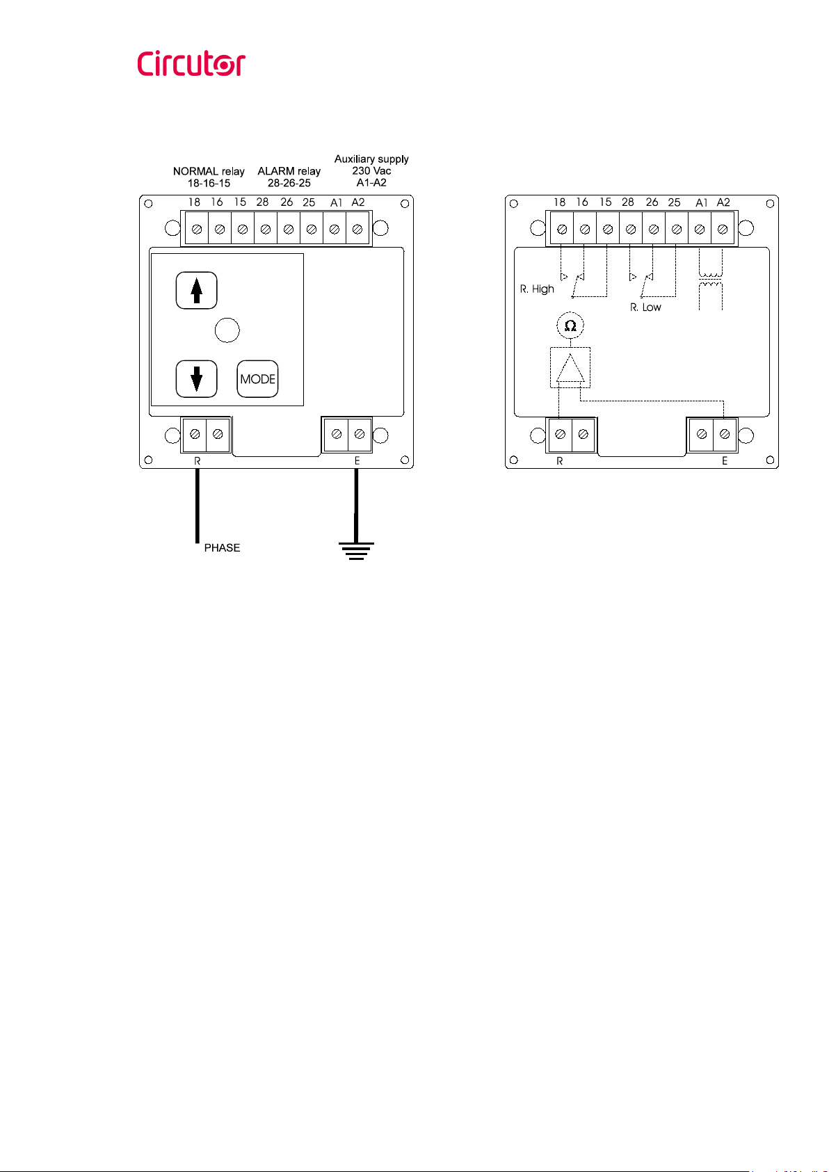
3.2.- MEG-1000 CONNECTION
3.2.1.- Connection terminals
Name
Concept
A1 -A2
Auxiliary supply of the device (230 Va.c. ±20 %)
E – R
Measuring of the insulation between a phase (R) and earth (E)
15 - 18 - 16
NORMAL relay with switchover contacts (free of voltage).
15-18: NO contact. 15-16: NC contact.
25 - 28 - 26 ALARM relay with switchover contacts (free of voltage).
25-28: NO contact. 25-26: NC contact.
MEG-1000
Page nº 6
3.2.2- Wiring diagram
MEG-1000
Page nº 7
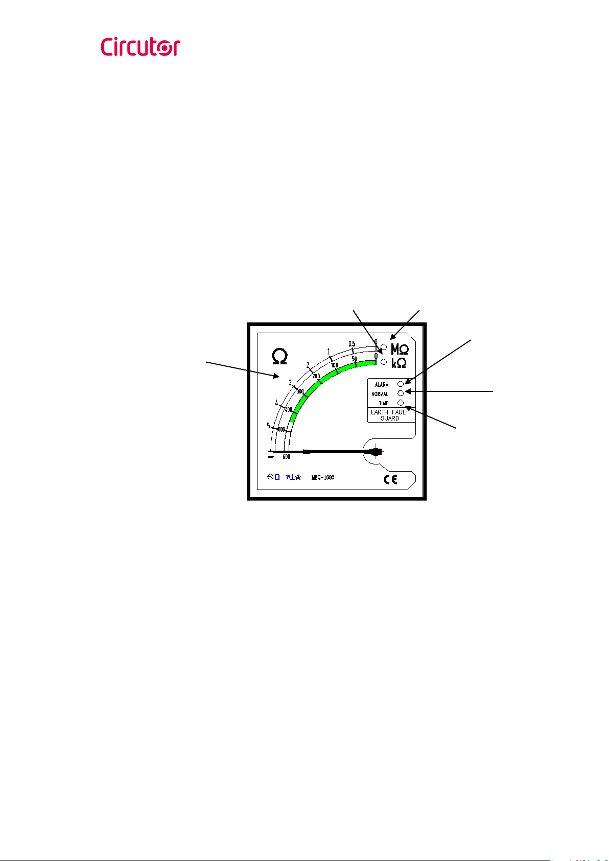
4.- OPERATION MODE
The user is informed about all the parameters by means of:
•Double scale galvanometer, that shows the value of the insulating resistance
(1).
•5 front plate leds:
-M
Ω
(2) and k
Ω
(3) leds indicate the measuring scale.
-ALARM (4) and NORMAL (5) leds indicate if the resistance is lower or
higher than the adjusted trip values.
-ALARM (4), NORMAL (5) and TIME (6) leds indicate the adjusted
parameter, when you are in adjusting mode.
(1)
(2)
(3)
(4)
(5)
(6)

MEG-1000
Page nº 8
The operation mode of the insulating guard is the following:
1. The device applies 24 Vd.c. voltage between the phase (R connection
terminal) and the ground (E connection terminal) and measures the
current.
2. The insulating resistance value, that is showed in the front plate
galvanometer (1), is obtained from the voltage and current values.
The instrument changes automatically the measuring scale, depending on the
value of the resistance. (2) and (3) yellow leds indicate whether the value is
referred to the MΩscale or to the kΩscale.
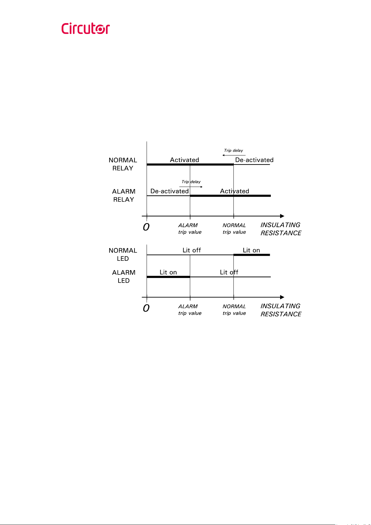
4.1.- OUTPUT RELAYS. OPERATION AND INDICATORS
Two output relays are available: ALARM relay and NORMAL relay. The trip value
and the delay time can be adjusted in each relay.
•NORMAL relay
While the insulating resistance is higher than the adjusted trip value the
NORMAL relay keeps de-activated. If the resistance being measured is lower
than the adjusted trip value the relay is activated after a set time.
Delay only takes place in relay activation; thus, when the resistance goes
beyond the relay trip value the relay is instantaneously de-activated.
NORMAL (5) green led lit on means that the insulating resistance is higher
than the NORMAL trip value.
MEG-1000
Page nº 9
•ALARM relay
While the insulating resistance is lower than the adjusted trip value the
ALARM relay keeps de-activated. If the resistance being measured is higher
than the adjusted trip value the relay is activated after a set time.
Delay only takes place in relay activation; thus, when the resistance lowers
under the relay trip value the relay is instantaneously de-activated.
ALARM (4) red led lit on means that the insulating resistance is lower than the
ALARM trip value.
In a chart:

MEG-1000
Page nº 10
4.2.- EQUIPMENT ADJUSTMENT
The equipment has three rear push buttons in order to adjust the ALARM and
NORMAL values and their corresponding temporisation:
•MODE push button
MODE push button gives access to different adjustments and allows to pass
from one adjustment to the other.
•Upward
↑
and downward
↓
push buttons
These two buttons adjust the selected value through the indication needle on
the scale.
In the adjustment mode the equipment has a safety temporisation. After 10
seconds without pressing one of the push buttons, the equipment automatically
goes back to working mode, only updating the values entered pressing MODE (see
adjustment sequence in page 12).
The pointer and the scale leds (kΩ(2) and MΩ(3)) show the trip value when it is
being adjusted. Any value within the measuring range can be adjusted. For a
properly operation of the instrument, the NORMAL relay trip value should be
higher than the ALARM relay trip value.

MEG-1000
Page nº 11
The pointer and the scale leds (kΩ(2) and MΩ(3)) show the delay time when it is
being adjusted:
-ALARM relay temporisation. Each 100 kΩmeans a trip delay of 1
second. The active measuring scale is the kΩscale. The adjusting range
is within 0.1 and 3 s.
-NORMAL relay temporisation. If the active measuring scale is the kΩ
scale, each 100 kΩmeans a trip delay of 1 second. If the active
measuring scale is MΩ, each 1 MΩmeans a trip delay of 10 seconds.
The adjusting range is within 0.1 and 30 s.
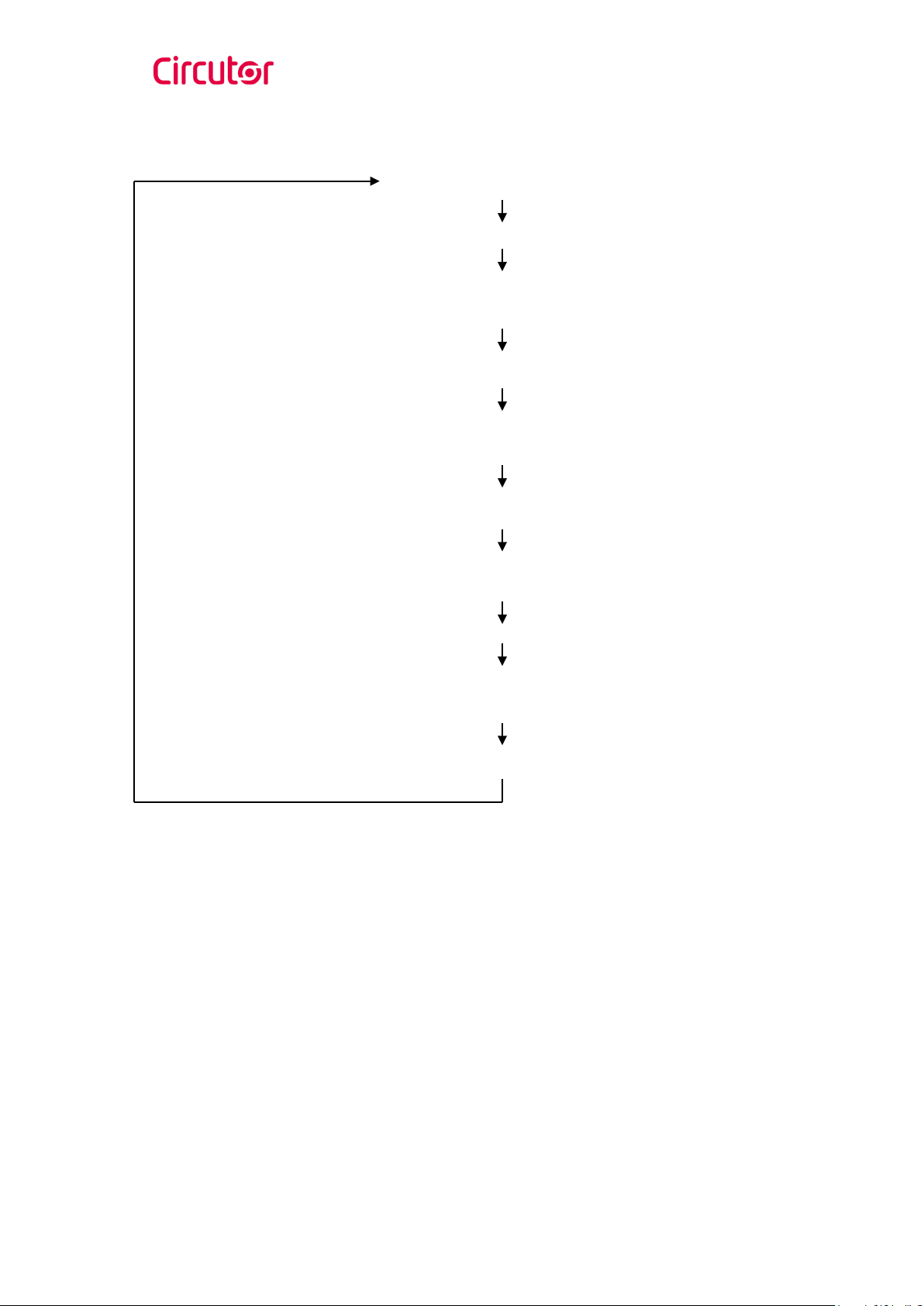
Adjustment push buttons give access to different adjustments according to the
following sequence:
MEG-1000
Page nº 12
OPERATION MODE
Press MODE
ADJUST OF THE “ALARM” RELAY TRIP VALUE
ALARM led blinks. Adjust the value by means of
↑
and
↓
Press MODE
ADJUST OF THE “ALARM” RELAY DELAY TIME
ALARM and TIME leds blink. Adjust the value by means of
↑
and
↓
Press MODE
ADJUST OF THE “NORMAL” RELAY TRIP VALUE
NORMAL led blinks. Adjust the value by means of
↑
and
↓
Press MODE
ADJUST OF THE “NORMAL” RELAY DELAY TIME
NORMAL and TIME leds blink. Adjust the value by means of
↑
and
↓
Press MODE

MEG-1000
Page nº 13
•Quick adjustment mode
Besides of the explained adjusting mode, the instrument has a “quick
adjustment” where the next default values are loaded:
ALARM relay trip value ................... 440 kΩ
ALARM relay delay time ................. 0.5 s
NORMAL relay trip value ................ 3 MΩ
NORMAL relay delay time ............... 3 s
In order to load these values all three push buttons (MODE,
↑
and
↓
) must be
pressed at the same time for a minimum of 2 seconds; during that time all led
blink simultaneously. When the leds are off the equipment returns to working
mode.
NOTICE: When pressing the three push buttons do not press MODE button first, otherwise
the equipment will go to adjustment mode.
5.- TECHNICAL CHARACTERISTICS
Auxiliary supply
Voltage: 230 V ±20% 50...60 Hz.
Consumption: 2.8 VA.
Measuring circuit
Measuring range: within 0 and 500 kΩ, in kΩmeasuring scale.
within 0.5 and 5 MΩ, in MΩmeasuring scale.
Accuracy:1.5 class
Maximum permanent voltage between E and R connection terminals: 1000 Va.c.
Voltage applied by the equipment between E and R connection terminals in order
to measure the insulating resistance: 24 Vd.c.

MEG-1000
Page nº 14
Output relays
Relays: ALARM (15-16-18) and NORMAL (25-26-28).
Type: mechanical, 3 terminals, free of voltage.
Use: AC11 250 V/8 A
Isolation between contacts: 1000 Va.c.
between coil and contacts: 4000 Va.c.
Relays temporisation adjustment
ALARM relay: from 0.1 to 3 s.
NORMAL relay: from 0.1 to 30 s.
Accuracy: ±10 %.
Isolation
Between any connection terminal and the case: 2.5 kV 50 Hz for 1 min.
Insulating resistance between the inputs, the outputs and the power supply:
1 GΩ.
Insulating resistance between any connection terminal and the case: 1 GΩ.
Working conditions
Working temperature: -20 / +50ºC.
Use: indoor.
Constructive characteristics
Case material: ABS self-extinguishing (as per UL 94 V1) and high resistance
against impacts.
Protection degree: Case: IP 52 / Terminals: IP 20
Screwed transparent cover for the adjustment push buttons.
Safety
Category I , EN-61010.
Standards
IEC 255-5, IEC 1010-1, EN 61010-1, IEC 801-2, IEC 801-3, IEC 801-4.

MEG-1000
Page nº 15
Dimensions:
Panel hole: 92 mm+0.8 x 92 mm+0.8
7.-SAFETY CONSIDERATIONS
All installation specification described at the previous chapters named
INSTALLATION AND STARTUP and SPECIFICATIONS.
Note that with the instrument powered on, the terminals could be dangerous to
touching and cover opening actions or elements removal may allow accessing
dangerous parts. This instrument is factory-shipped at proper operation condition.

MEG-1000
Page nº 16
8.- MAINTENANCE
The MEG-1000 does not require any special maintenance. No adjustment,
maintenance or repairing action should be done over the instrument open and
powered and, should those actions are essential, high-qualified operators must
perform them.
Before any adjustment, replacement, maintenance or repairing operation is carried
out, the instrument must be disconnected from any power supply source.
When any protection failure is suspected to exist, the instrument must be
immediately put out of service. The instrument’s design allow a quick replacement
in case of any failure.
9.- TECHNICAL SERVICE
For any inquiry about the instrument performance or whether any failure happens,
contact to CIRCUTOR’s technical service.
CIRCUTOR S.A. - After sales service :902 449 459 (SPAIN) / (+34) 937 452 919
Vial Sant Jordi, s/n
08232 - Viladecavalls (Barcelona) - España
Tel: (+34) 973 452 000
Fax:(+34) 973 452 914
e-mail: sat@circutor.com–
This manual suits for next models
1
Table of contents
Other Circutor Test Equipment manuals


