Spandau pumpen PXK Series User manual
Product name
Centrifugal pumps
Product line: PXA… / PXK…
Original installation instruction with included
operating manual
in accordance with EC-Machinery
Directive 2006/42/EC
Version 02

Imprint page 2
EN
mprint
This original installation instr ction with incl ded
operation man al complies with EC-Machinery
Directive 2006/42/EC and is an integral part of the
described prod ct. It m st be kept for f t re se.
This original installation instr ction with incl ded
operation man al was created in accordance with
the valid standards and reg lations on doc menta-
tion, VDI 4500 and EN 292.
© SKF Lubrication Systems Germany AG
This doc mentation is protected by copyright. The
photomechanical reprod ction, copying, and distri-
b tion of this doc mentation or parts thereof by
means of processes s ch as data processing, data
carriers, and data networks is strictly prohibited
witho t the express permission of SKF L brication
Systems Germany AG.
We reserve the right to make content and technical
changes.
Service
If yo have technical q eries, please contact one of
the following plants:
SKF L brication Systems Germany AG
Prod ct range Spanda P mpen
Motzener Straße 35/37
12277 Berlin
Germany
Tel. +49 (0)30 72002-0
Fax +49 (0)30 72002-261
Kontakt@Spanda p mpen.de
www.spanda p mpen.com

Table of contents page 3
EN
Table of contents
Original installation instruction in accordance
with EC-Machinery Directive 2006/42/EC
mprint 2
Service 2
Table of contents 3
nformation concerning the EC Declaration of
Conformity and the EC Declaration of
ncorporation 4
General information 5
Meaning of symbols and corresponding
information 5
1. Safety information 7
1.1 Intended se 7
1.2 A thorized personnel 8
1.3 Danger relating to electric c rrent 8
1.4 Danger relating to hydra lic press re 8
2. Fluids delivered 9
3. Assemblies and type designation 10
4. Composition and function 11
5. nstallation instruction 12
5.1 Positioning and mo nting 12
5.2 Connecting dimensions 14
5.3 Installation of Pipes 14
5.4 Connection of Pipes 14
5.5 Fastening to the Container 14
5.6 Electrical connection 15
5.7 Sense of Rotation 15
Operating manual 16
6. Transport, delivery and storage 17
6.1 P mps 17
6.2 Electronic and electrical devices 17
6.3 General information 17
7. Start-up and operation 18
8. Shutdown 19
8.1 Temporary sh tdown 19
8.2 Definitive sh tdown 19
9. Maintenance 20
9.1 General notes 20
9.2 Disassembly and Assembly PXA 21
9.2.1 Disassembly of the P mp 21
9.2.2Assembly of the P mp 22
10. Faults 25
11. Technical data 28
11.1 Design feat res 28
11.2 Mechanical design 28
11.3 Electrical design 28
11.4 Meas rements 29
12. Notes 33

Information concerning the EC Declaration of Conformity and the EC Declaration of Incorporation page 4
EN
nformation concerning the EC Declaration of Conformity and the EC Declaration of
ncorporation
For the prod ct(s) designated below:
Centrifugal pump
Prod ct line:
PXA… / PXK…
SKF herewith certifies that it conforms to the perti-
nent safety req irements set forth in the following
Co ncil Directive(s) for the harmonisation of the
laws of the Member States...
•Machinery Directive 2006/42/EC
•Low-voltage Directive 2006/95/EC
•Electromagnetic compatibility 2004/108/EC
Notes:
(a) This declaration certifies conformity with the
aforementioned directive(s), b t does not
contain any ass rance of properties.
(b) The safety instr ctions in the doc mentation
incl ded with the prod ct m st be observed.
(c) The certified prod ct m st not be started p
ntil it is ass red that the machine, vehicle or
the like in which the prod ct was installed
meets the provisions and req irements of the
national directives to be applied. This is in par-
tic lar important for the implementation of the
Use of Work Directive.
(d) Operation of the prod cts on non-standard
mains voltage as well as nonobservance of in-
stallation instr ctions can affect the EMC
properties and electrical safety.
SKF f rther declare that the above mentioned
prod ct:
•is meant for integration into a machine / for
connection to other machinery according to
the EC-Machinery Directive 2006/42/EC,
Appendix Part B. Starting p the prod ct
is not admissible ntil it is ass red that the
machine, vehicle or the like in which the
prod ct was installed meets the provisions
and req irements of the reg lations set forth
in the EC Directive 2006/42/EC.
•with reference to the EC Directive 97/23/EC
concerning apparatus subjected to
pressure this prod ct m st only be sed as
intended and according to the notes in the
doc mentation. Especially observe the
following:
Prod cts of SKF L brication Systems Germany AG
m st not be sed in con¬j nction with fl ids, gro p
I (hazardo s fl ¬ids), according to the definition of
article 2 paragraph 2 of the Directive 67/548/EC
dtd. 27th J ne, 1967; and are not approved for
application with s ch.
None of the prod cts man fact red by SKF L -
brication Systems Germany AG are approved for
application in con¬nection with gases, liq efied
gases, gases dissolved nder press re, steams or
fl ids that will reach a steam press re of more
than 0.5 bar above the normal atmospheric
pres¬s re (1013 mbar) in the admissible ap-
plica¬tion temperat re range.
When sed as intended, the prod cts s p¬plied by
SKF L brication Systems Germany AG do not
reach the limit val es listed in the Article 3 par. 1,
sections 1.1 to 1.3 and par. 2 of the Press re
Eq ipment Directive 97/23/EC. Therefore they do
not come nder the req irements set forth in
annex I of that Directive. They are not labelled with
the CE mark with reference to the Directive
97/23/EC. They are classified by s to come nder
Article 3 par. 3 of the Direc¬tive.
The EC Declaration of Conformity and EC-Declara-
tion of Incorporation is part of the prod ct doc -
mentation. These doc ments are delivered with
the prod ct.
General information page 5
EN
General information
Meaning of symbols and corresponding
information
In this installation instr ction, these symbols are
sed to highlight safety information that comm -
nicates a partic lar risk to persons, material assets,
or the environment.
Pay attention to this information and be especially
caref l in sit ations where a risk is indicated. Pass
on all safety instr ctions to other people as appro-
priate.
Hazard symbols
Information that is attached directly to the prod ct
- s ch as the examples below - m st be observed.
S ch signs m st be kept in a legible state.
•Rotational direction arrow
•Fl id connection label
Keywords in safety information and their
meanings
The responsibility is yours!
Read this installation instr ction thoro ghly and
pay attention to the safety information.
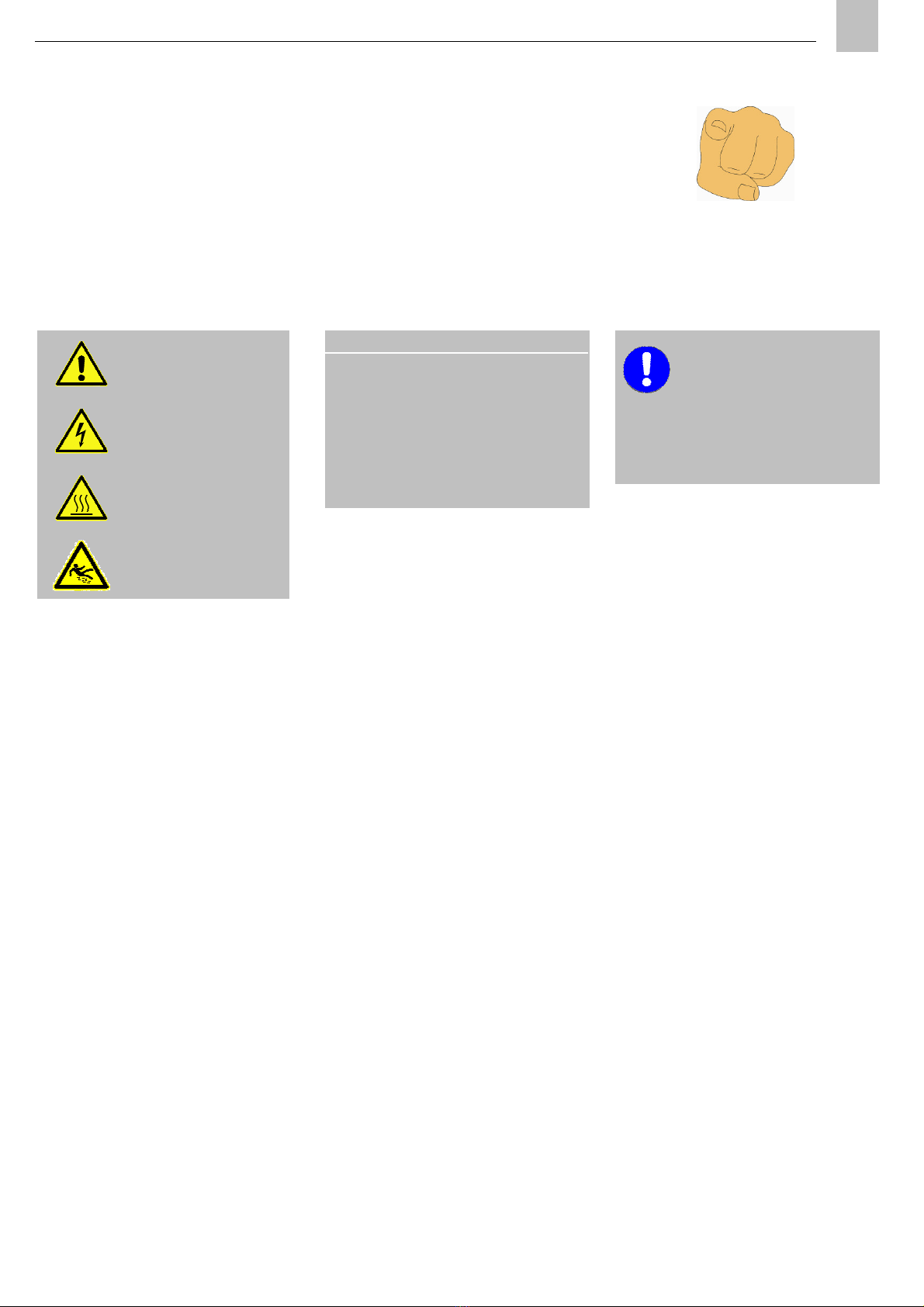
nformation symbols
D N 4844-2
W000
General
risk
D N 4844-2
W008 Voltage
D N 4844-2
W026
Hot
surface
D N 4844-2
W028
Slip
hazard
Keyword Use
Danger! Indicates a danger of inj ry to
persons
Caution! Indicates a danger of damage
to property or the environment
Note! Indicates additional
information
Note
⇒ Prompts yo to take action
• Used for b lleted lists
> Indicates other iss es, ca ses or
circ mstances
∗ Provides additional information

Product name
Centrifugal Pump
Product line: PXA… / PXK…
Original installation instruction
in accordance with
EC-Machinery Directive 2006/42/EC

1. Safety information page 7
EN
1. Safety information
Please observe the following safety instr ctions to
ens re tro ble-free f nctioning of the nit and
prevent damage.
The operator of the described prod ct
m st ens re that this installation in-
str ction is read and nderstood by all
persons who are involved with the as-
sembly, operation, maintenance, and
repair of the prod ct. This installation
instr ction m st be kept close at hand.
Note that this installation instr ction is
an integral part of the prod ct. It m st
be handed over to the new operator of
the prod ct if the prod ct is sold.
The described prod ct was man fact red in accor-
dance with all generally acknowledged reg lations
pertaining to technology, occ pational safety, and
accident prevention. However, dangers that can
ca se physical inj ry to persons or damage to
other material assets might still occ r d ring the
se of the prod ct. This prod ct sho ld therefore
only be sed if it is in a technically perfect state and
with f ll observance of the information provided in
this installation instr ction. In partic lar, malf nc-
tions that might affect the safety of the prod ct
m st be rectified immediately.
Especially errors that co ld affect safety m st be
resolved witho t delay.
Safety meas res corresponding to the parameters
of the l bricant s pplied m st be stip lated.
The safety mechanisms m st not be damaged,
dismantled, or in any way made inoperable, nor
m st they be replaced by parts which have not
been expressly approved of by VOGEL.
In addition to the information provided
in the installation instr ction, all gener-
ally valid reg lations on accident pre-
vention and the environment m st be
observed.
1.1 Intended se
All SKF L brication Systems Germany
AG prod cts may only be sed for their
intended p rpose and in accordance
with the specifications of the installation
instr ction for the prod ct in q estion.
Spanda P mpen Immersion p mps, type PXA or
PXK, are m lti-stage centrif gal p mps for
p mping of mineral oil based oils and em lsions as
well as synthetic cooling and l brication agents
witho t abrasive and long fibro s components.
They are designed for vertical installation.
Any other se of this prod ct constit tes improper
se.
Only a thorized l bricants for the p mp
type may be s pplied. Uns itable
l bricants co ld lead to the p mp failing
and possibly severe property damage
and personal inj ry.
Una thorized modifications to the
p mps and the se of na thorized
spare parts and aids are prohibited and
void the warranty.
Worn-o t nits m st be made inoperable and
disposed of properly.
1. Safety information page 8
EN
Prod cts of SKF L brication Systems Germany AG
m st not be sed in con¬j nction with fl ids, gro p
I (hazardo s fl ¬ids), according to the definition of
article 2 paragraph 2 of the Directive 67/548/EC
dtd. 27th J ne, 1967; and are not approved for
application with s ch.
None of the prod cts man fact red by SKF L -
brication Systems Germany AG are approved for
application in con¬nection with gases, liq efied
gases, gases dissolved nder press re, steams or
fl ids that will reach a steam press re of more
than 0.5 bar above the normal atmospheric
pres¬s re (1013 mbar) in the admissible ap-
plica¬tion temperat re range.
If it is not shown separately prod cts of SKF
L brication Systems Germany AG m st not be
sed in areas exposed to explosion hazards as
discribed in the ATEX Directive 94/9/EC.
1.2 A thorized personnel
The prod cts described in the installation instr c-
tion may only be installed, operated, maintained,
and repaired by q alified experts. Q alified experts
are persons who have been trained, instr cted, and
familiarized with the end prod ct into which the
described prod ct is installed. These persons are
considered capable of s ch tasks d e to their
ed cation, training, and experience with valid
standards, conditions, accident prevention reg la-
tions, and assembly meas res.
They are entitled to carry o t the req ired tasks
and to recognize - and th s avoid - any dangers
that might otherwise occ r.
A definition of what constit tes a q alified person
and information on the prohibition on allowing
work to be carried o t by nq alified personnel are
stip lated in DIN VDE 0105 and IEC 364.
1.3 Danger relating to electric c rrent
The electrical connection for the described prod ct
may only be established by q alified, instr cted
persons who have been a thorized to carry o t the
task at hand by the operator. All local electrical
operating conditions and reg lations s ch as DIN
and VDE m st be observed. Improperly connected
prod cts can res lt in considerably damage to
property and inj ry to persons.
Working on prod cts that have not been
disconnected from the power s pply can
ca se inj ry to persons.
Assembly, maintenance, and repair
work may only be carried o t by q ali-
fied experts on prod cts that have been
disconnected from the power s pply.
The s pply voltage m st be t rned off
before any prod ct components are
opened.
1.4 Danger relating to hydra lic
press re
The described prod ct is nder press re
when it is being operated. The prod ct
m st therefore be depress rized before
starting assembly, maintenance, or re-
pair work and before making any
changes to the system.

2. Fl ids delivered page 9
EN
2. Fluids delivered
•Clean, t rbid and air-free fl ids witho t long-
fibered or abrasive constit ents
•Low viscosity cooling and c tting oils, mineral
and synthetic types
•Aq eo s em lsions
•Water
•Cleaning liq ids
•Acids and bases
The following limit values m st be complied with
when contaminated or highly visco s fl ids are
involved:
Max. gain size:
Ø
2mm with PXA/PXK 02/04
Ø
3mm with PXA 10/18
Max.
contamination:
50 g/m
3
bei PXA/PXK 02/04
100 g/m
3
bei PXA 10/18
Max. kinematic viscosity 20 mm
2
/s
Check the motor power when the density or
viscosity deviates from that of water.
Temperat re range: -10°C bis +90°C
3. Assemblies and type designation page 10
EN
3. Assemblies and type designation
Spanda P mpen Immersion p mps, type PXA or
PXK, are offered in different sizes which mainly
differ in dimension and p mping o tp t. The
f nctional principle of all sizes is identical.
The respective size or designation of yo r p mp as
well as f rther important identification data is
given on the nameplate.
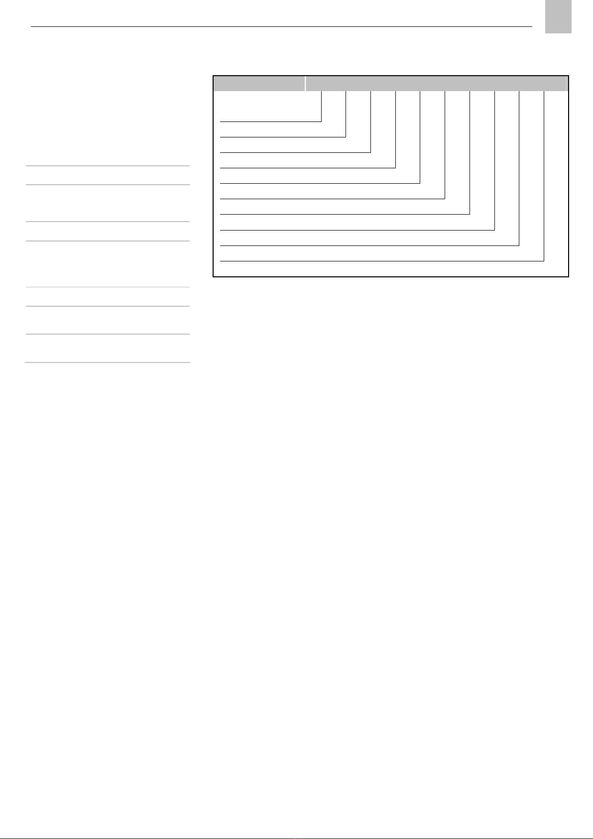
Series PXA
PXK
p to 25bar
p to 7bar
Size 02
04
10
18
2 m³/h
4 m³/h
10 m³/h
18 m³/h
N mber of stages 02 - 25 N mber of
active stages
Materials G
E
Cast iron
(standard)
stainless steel
(only PXA/PXK
02/04)
Seal types B
G
Split b sh
Glide ring seal
P mp version S
V
Basic version
prepared for
extension pipe
Immersion depth 185 bis 626 Immersion
depth of p mp
in mm
Table 1. Type key
Designation PXA 04 02 G B S 185 D 01 AA
Series
Size
N mber of stages
Materials
Seal type
P mp version
Immersion depth
Motor size index1)
Electric s pply1)
Motor version1)
1) The motor data can be extracted from the motor’s nameplate.
4. Composition and f nction page 11
EN
4. Composition and
function
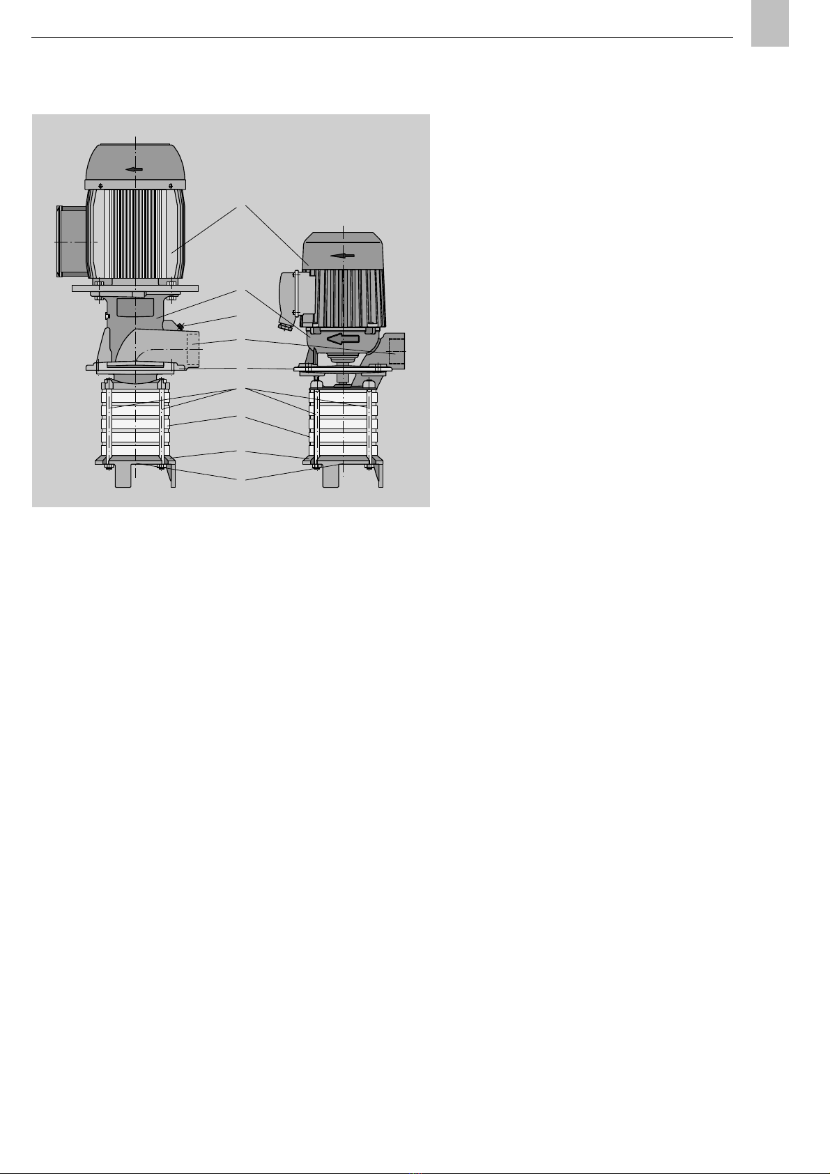
Fig.1 shows the principle design of the p mps PXA
or PXK.
The p mps are sed in s ction operation. They are
designed for vertical installation.
The electric drive (1) is installed on the p mp
connector (2), to which the individ al p mp stages
(7) are fastened by means of tie rods (6).
The connector ho ses the p mp shaft bearing and
the sealing. The press re connection (4) and the
assembly flange (3) for installation on the medi m
container are likewise part of the connector. The
p mp PXA also feat res a venting screw (5) near
the press re connection.
A variable n mber of p mp stages s pplies the
medi mn that is drawn in at the p mp bottom (8)
thro gh the intake opening (9).
Fig.: 1. Design of the
pumps PXA and PXK
1 Drive
2 Pump connector
3 Assembly flange
4 Pressure connection
5 Venting screw (PXA
only)
6 Tie rod
7 Pump stage
8 Pump bottom
9 ntake opening
1
6
5
4
3
2
7
8
9
PXA
PXK

5. Installation instr ction page 12
EN
5. nstallation instruction
The prod ct described in the installation instr ction
may only be installed, operated, maintained, and
repaired by q alified experts. Q alified experts are
persons who have been trained, instr cted, and
familiarized with the end prod ct into which the
described prod ct is installed. These persons are
considered capable of s ch tasks d e to their
ed cation, training, and experience with valid
standards, conditions, accident prevention reg la-
tions, and operating meas res. They are entitled to
carry o t the req ired tasks and to recognize - and
th s avoid - any dangers that might otherwise
occ r.
A definition of what constit tes a q alified person
and information on the prohibition on allowing
work to be carried o t by nq alified personnel are
stip lated in DIN VDE 0105 and IEC 364.
Before assembling/positioning the prod ct, remove
the packaging material and any transportation
safety devices s ch as sealing pl gs. Keep the
packaging material ntil yo are s re that there
are no delivery discrepancies that need to be
clarified.
The prod ct m st not be tipped p or
dropped.
Regional accident prevention reg lations and the
operating and maintenance instr ctions of the
operator m st be observed when carrying o t all
assembly work on machines.
5.1 Positioning and mo nting
Immersion p mps, type PXA and PXK, are
designed for vertical installation inside the medi m
container. If yo need a p mp that can be installed
in a different position, please contact yo r p mp
s pplier.
Before installing the p mp, remove packing
materials and transport safety devices (e.g. blind
pl gs in the intake and press re connections).
The p mp m st be transported only by means of
the transport eyes.
If an intake pipe has been ordered, it is s pplied
separately and m st be screwed seal tight into the
conical thread in the intake ho sing before the
p mp is installed. Select the sealing material in
harmony with the operating conditions and
temperat res.
When installing the intake pipe, ens re that the
sealing material does not enter the interior of the
p mp or the pipe.
To allow installation of the p mp on the container
ho sing, the p mp has a 4-hole installation flange
with standard dimensions (see specifications).
When selecting the installation site, ens re
s fficient space for installation, cabling, inspection
and ventilation. The distance between the air
intake of the motor and walls, components etc.
m st be at least ¼ of the diameter of the air intake
opening. The air flow direction is from the air
intake opening to the p mp.
5. Installation instr ction page 13
EN
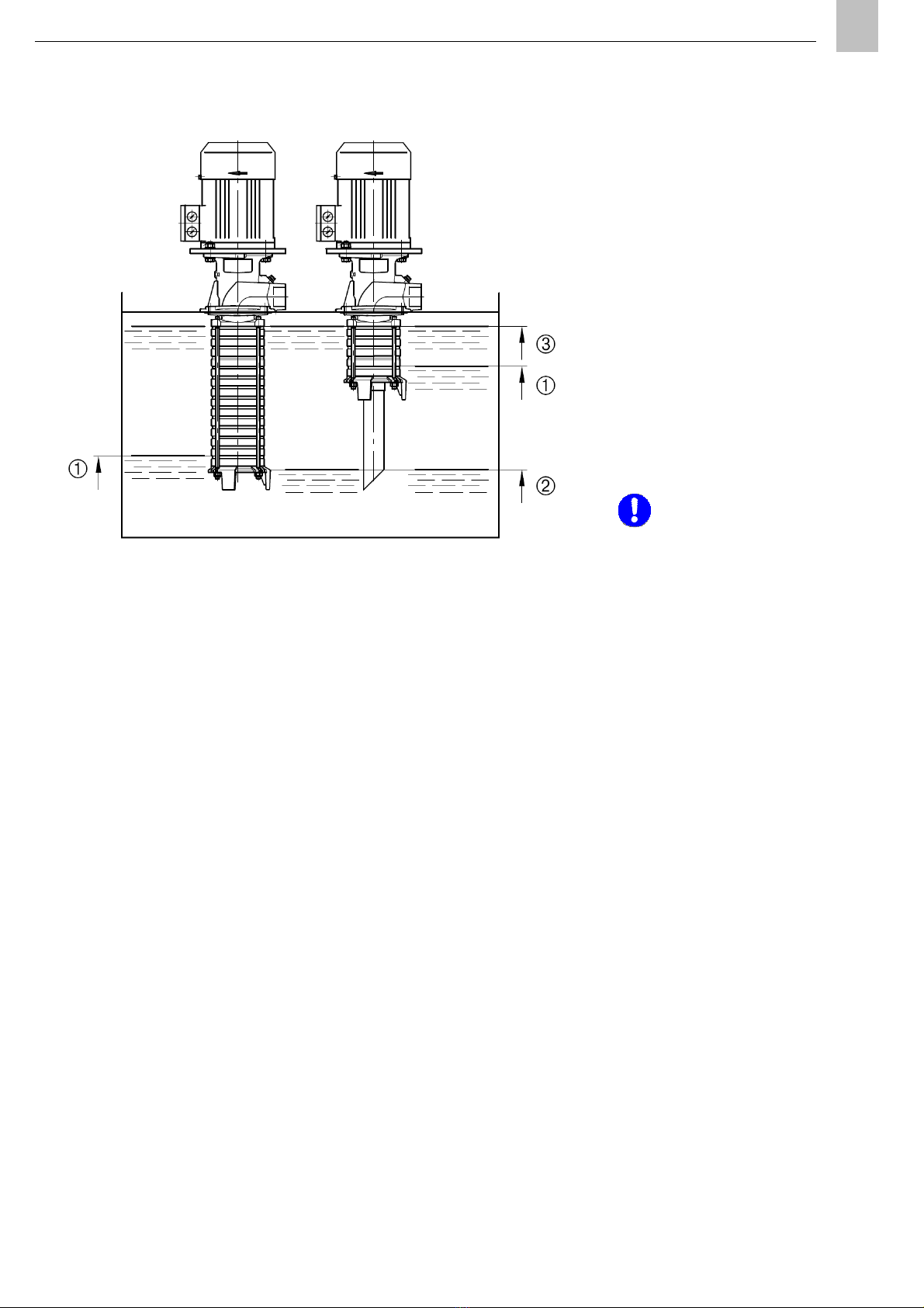
Versions:
with empty intermediate chambers
with extension t be
When installing the p mp, take the maxim m and
minim m fl id levels into consideration (Fig.2).
When the p mp is switched on the minim m level
of fl id has to be above the bottommost p mp
chamber
.
The p mp then delivers all the way to the intake in
the chamber or t be
. The maxim m permissible
level of fl id amo nts to 30mm below the
reservoir’s cover
.
The prod ct sho ld be mo nted in a way that
protects it from h midity and vibrations. It sho ld
also be easily accessible so that all other installa-
tion work can be carried o t witho t problems.
Make s re that there is a s fficient amo nt of
circ lating air to prevent the excessive heating of
the prod ct. For information on the maxim m
permitted ambient temperat re, see the technical
data.
The prod ct m st be installed vertically in accor-
dance with the specifications of the c stomer
doc mentation.
If no c stomer doc mentation is
available, c stomer doc mentation can
be req ested directly from SKF
L brication Systems Germany AG.
Fig. 2: different delivery characteristics at the same immersion depth

5. Installation instr ction page 14
EN
5.2 Connecting dimensions
Flange and port dimensions to DIN EN 12157
5.3 Installation of Pipes
When installing pipes, observe the following notes
to ens re tro ble-free f nction of the p mping
circ it:
•All elements of the p mping circ it, s ch as
pipes, sh t-off armat res, valves etc., which
come in contact with the medi m m st be
cleaned caref lly. Inside the lines, seals m st
not protr de toward the interior, to prevent
contaminants from reaching the interior of the
p mp and ca sing damage or destroying the
p mp.
•Use only pipes or hoses which are s itable for
the operating press re of the respective p mp,
the prevailing temperat res and the media to
be p mped.
•The lines m st be connected so that no force
is transmitted to the p mp ( nconstrained
connection). Therefore it is recommended to
install the press re lines to the p mp before it
is fastened to the container cover.
•The flow of the medi m in the lines sho ld not
be obstr cted by sharp bents, edge valves and
ret rn flaps. Unavoidable red ctions of the
line's cross-section m st be softened by
sloping transitions. S dden changes of the
flow direction m st be avoided in any case.
•The lines m st be seal tight and installed in
s ch a way that air may not be sh t in at any
point.
•The pipes sho ld always be laid o t rising. It
sho ld be possible to vent press re lines at the
highest spot.
•The cross-section of the press re line sho ld
at least reach the cross-section of the
press re connection.
5.4 Connection of Pipes
The pipes are connected to the press re ho sing of
the p mp at the connection provided. Ens re that
no force is transmitted to the p mp.
Connect the pipe with a flat face end seal and a
cylindrical thread. If tapered threads are sed, a
s itable sealing material m st be sed.
The screw-in torq e sho ld not exceed 70 Nm,
since the p mp connector may otherwise b rst or
break off.
5.5 Fastening to the Container
Once the press re line has been installed, the
p mp can be fastened to the container at a
maxim m tightening torq e of 15 Nm.

5. Installation instr ction page 15
EN
5.6 Electrical connection
The p mp may be connected only by
properly q alified and instr cted
personnel. Comply with the notes in this
operating man al.
Connect the p mp motor according to the
information on its nameplate considering the
s pply voltage available on site.
For installation, observe the applicable standards,
s ch as VDE 0100, VDE 0101, and VDE 0165, as
well as the req irements of the local energy
s pplier.
Cables and lines m st be fastened to the terminal
box with a cable fitting incl ding strain relief.
Connect the motor according to the electric
diagram in the terminal box of the motor.
If the p mp has been stored for a longer period in
a h mid room, the isolation resistance between
motor winding and p mp ho sing sho ld be
meas red.
At a winding temperat re of abo t 20 °C the
minim m resistance for low voltage motors is 1 kΩ
per Volt rated voltage. If the resistance is lower,
the motor m st be dried in a warm room or with
heating devices, ntil the req ired isolation
resistance is reached.
5.7 Sense of Rotation
The sense of rotation of the motor m st agree with
the arrow on the p mp. To check the sense of
rotation, open the valves in the press re and intake
lines and switch the motor on for a short time
(approx. 1 s).
Wrong sense of rotation will damage the
p mp.

Product name
Centrifugal pump
Product line: PXA… / PXK…
Operating manual

6. Transport, delivery and storage page 17
EN
6. Transport, delivery
and storage
SKF L brication Systems Germany AG prod cts
are packaged as is s al in the trade in
accordance with the reg lations of the recipient
co ntry and in accordance with DIN ISO 9001.
O r prod cts m st be transported with care.
Prod cts m st be protected against mechanical
infl ences s ch as impacts. Transport
packaging m st be labelled with the
information 'Do not drop!'.
The prod ct m st not be tipped p
or dropped.
There are no restrictions relating to land, air, or
sea transportation.
Following receipt of the shipment, the prod ct
or prod cts m st be checked for damage and
the shipping doc ments sho ld be sed to
make s re that the delivery is complete. Keep
the packaging material ntil yo are s re that
there are no delivery discrepancies that need to
be clarified.
The following conditions apply to the storage of
SKF L brication Systems Germany AG
prod cts:
6.1 P mps
•The p mp m st be transported only by
means of the transport eyes (if provided).
•For storage ens re dry, d st-free and low-
vibration (veff 0.2 mm/s) environment.
We recommend to store the nit in vertical
position.
•If stored for longer periods, the sability
period of the grease in the bearings is
red ced.
•If the nit is stored for more than 12
months, the condition of the grease m st
be checked before the nit is taken into
operation. Also, the isolation resistance
between motor winding and ho sing m st
be meas red. If the resistance is 1 k per
Volt rated voltage, the motor winding m st
be dried.
6.2 Electronic and electrical devices
•Ambient conditions: Dry, d st-free
environment; storage in well-ventilated,
dry area
•Storage time: 24 months max.
•Permitted air h midity: < 65%
•Wareho se temperat re: 10 - 40°C
•Light: Direct s nlight/UV radiation m st be
avoided; nearby so rces of heat m st be
screened
6.3 General information
•Ens re that no d st gets into stored
prod cts by wrapping them in plastic film
•Store prod cts on racks or pallets to
protect them from rising damp
•Before placing prod cts into storage,
protect ncoated metal s rfaces - and
drive parts and mo nt s rfaces in
partic lar - from corrosion sing long-
term corrosion protection
•At 6-monthly intervals: Check prod cts for
corrosion. If signs of corrosion are fo nd,
improve the corrosion protection
meas res.
•Drives m st be protected against
mechanical damage

7. Start- p and operation page 18
EN
7. Start-up and
operation
Before taking it into service, all connections at
the p mp m st be checked. Be s re, the intake
and press re connections of the p mp are
nstopped.
The p mp m st r n smoothly and evenly. To
perform checks, yo can remove the fan hood
and spin the p mp shaft several times by
t rning the fan impeller man ally. Be s re to
reinstall the fan hood afterward.
Check the sense of rotation of the p mp pon
start- p. It m st agree with the direction
indicated by the arrow on the press re ho sing.
The container m st be filled with fl id to the
level indicated in section “Set p”.
The p mp m st not r n dry. Wrong
sense of rotation and/or dry r n may
damage the p mp.
Also ens re that no inadmissible dirt is inside
the container or piping system and that the
intake filter works properly.
PXA
Take the p mp PXA into operation as follows:
•Close the sh t-off valve on the press re
side.
•Open the venting screw.
Take care of the direction of the
venting opening points in order to
prevent being hit by escaping fl id.
•Switch on the p mp and check the sense of
rotation. It m st agree with the direction
indicated by the arrow on the p mp
ho sing.
•Open the sh t-off valve on the press re
side a little, allowing the medi m to flow
thro gh.
•Close the venting screw as soon as fl id
drools from the valve.
•Now yo can open the sh t-off valve on
the press re side.
PXK
Take the p mp PXK into operation as follows:
•F lly open the sh t-off valve on the
press re side - if installed - and ens re the
press re connection is nstopped.
•Switch on the p mp and check the sense of
rotation. It m st agree with the direction
indicated by the arrow on the p mp
ho sing.
•Let the p mp r n ntil a stable s pply
condition is reached or no more air b bbles
are visible in the medi m.
•Now yo can adj st the req ired s pply
vol me sing the sh t-off valve on the
press re side.
The p mps sho ld be operated on a contin o s
basis whenever possible. If, for example, that is
not possible for technical reasons, constant
p mp delivery can be reg lated by an control
valve or the like.
If the p mp is to be operated intermittently at
short intervals, please contact the s pplier for
cons ltation.

8. Sh tdown page 19
EN
The p mp m st be operated only within the
defined o tp t range. The respective
identification data is given on the nameplate of
the p mp.
When the p mp operation is interr pted, the
minim m fl id level may drop to the intake
opening. However, ens re that the fl id level
will not drop f rther d ring operation, since the
p mp will otherwise r n dry.
When the p mp stands still, the filling level
m st not drop below the val e indicated in
chapter “Assembly” in section “Set p”.
Otherwise the p mp might r n dry when the
p mp starts and the filling level drops.
The p mp m st not r n dry, since it
may otherwise be damaged.
8. Shutdown
8.1 Temporary sh tdown
Yo temporarily sh t down the described
prod ct by disconnecting the electrical,
pne matic, and/or hydra lic s pply
connections. For more information, see the
section 'General information' in this installation
instr ction.
If yo wish to sh t down the prod ct for a
longer period of time, refer also to the
instr ctions in the section 'Transport, delivery,
and storage' of this installation instr ction.
When placing the prod ct back into operation,
pay attention to the information in the sections
'Assembly' and 'Start- p of this installation
instr ction.
8.2 Definitive sh tdown
All regional legal g idelines and legislation on
the disposal of contaminated eq ipment m st
be observed when sh tting down the prod ct
for the final time.
L bricants can contaminate the
gro nd and waterco rses.
L bricants m st be sed and
disposed of properly. Regional
reg lations and laws on the se and
disposal of l bricants m st be
observed.
In exchange for the inc rred costs, SKF
L brication Systems Germany AG can take back
the prod ct and arrange for its disposal.

9. Maintenance page 20
EN
9. Maintenance
9.1 General notes
Working on prod cts that have not
been disconnected from the power
s pply can ca se inj ry to persons.
Assembly, maintenance, and repair
work may only be carried o t by
q alified experts on a prod ct that is
not connected to a power s pply.
The s pply voltage m st be
disconnected before any prod ct
components are opened.
The described prod ct is nder
press re when it is being operated.
The prod ct m st therefore be
depress rized before starting
assembly, maintenance, or repair
work and before making any
changes to the system.
Immersion p mps, type PXA or PXK, are largely
maintenance-free. To ens re perfect f nction,
yo sho ld check the p mp reg larly for
exterior damage or leakage.
The medi m p mped as well as intake filters
and screens sho ld be checked reg larly for
contamination and sho ld be cleaned or
replaced as needed.
Also, ens re that the ho sing of the p mp
motor remains free from d st, foreign objects
etc., to ens re good heat exchange between
motor and ambient air for nhindered s rface
heat dissipation.
All electrical connections and lines m st be
checked reg larly for damage and to ens re
that they are firmly in place.
Any fa lts fo nd m st be properly rectified
before the p mp is activated again.
Yo m st not dismantle the prod ct
or parts therefore d ring the
stat tory g arantee period. Doing so
invalidates all g arantee claims.
Only original SKF L brication
Systems Germany AG spare parts
may be sed. Yo m st not carry o t
alterations to the prod ct or se
non-original spare parts or
reso rces. Doing so invalidates the
stat tory g arantee.
SKF L brication Systems Germany AG is not
liable for damage ca sed by improper
assembly, maintenance, or repair work.
This manual suits for next models
5
Table of contents
Other Spandau pumpen Water Pump manuals

Popular Water Pump manuals by other brands


SEW-Eurodrive
SEW-Eurodrive MOVIMOT MM..D Series Addendum to owner's manual

Zoeller
Zoeller 503 Installation guides

Coleman
Coleman 120V QuickPump How to use and enjoy

BRINKMANN PUMPS
BRINKMANN PUMPS SBA1600 operating instructions

Ismatec
Ismatec MCP-CPF Process operating manual

KSB
KSB RPH Series operating instructions

Ceco
Ceco Sethco 2500 Series Operation manual

SPX
SPX Johnson Pump F2P10-19 1/2 slang 12 V instruction manual

Graco
Graco Check-Mate 450 Instructions-parts list

Graco
Graco 231169 Instructions-parts list

Gardena
Gardena 1490 operating instructions

Wilo
Wilo VeroLine-IPH-O Installation and operating instructions