Sparrow IMS-130 User manual

- 1 -
Sparrow
IEEE 1394b Industrial CCD Camera
IMS-130
User’s Manual
Manual Version: 1.2
Release Date: July 15, 2010
ICP DAS Co., LTD. ww.icpdas.com

- 2 -
Table of Contents
1. Introduction ............................................................................................................5
1.1 Features................................................................................................................................... 5
1.2 Applications.............................................................................................................................. 5
1.3 System Requirement ............................................................................................................... 5
1.4 Function Descriptions .............................................................................................................. 7
1.4.1 AOI (Area of Interest).................................................................................................. 7
1.4.2 Brightness ................................................................................................................... 8
1.4.3 Sharpness................................................................................................................... 8
1.4.4 White Balance............................................................................................................. 8
1.4.5 Hue.............................................................................................................................. 9
1.4.6 Saturation.................................................................................................................... 9
1.4.7 Gamma and LUT....................................................................................................... 10
1.4.8 Gain........................................................................................................................... 10
1.4.9 Shutter (Exposure).................................................................................................... 10
1.4.10 Trigger Control ...........................................................................................................11
1.4.11 GPIO (General Purpose Digital Input and Output) ................................................... 13
1.4.12 Strobe Control........................................................................................................... 16
1.4.13 Save Camera Configuration...................................................................................... 16
1.4.14 Data Flash Control .................................................................................................... 16
1.4.15 Software AES Project Encryption.............................................................................. 17
1.4.16 Test Pattern............................................................................................................... 17
1.5 Spectral Response................................................................................................................. 18
1.6 Benchmarks........................................................................................................................... 19
1.6.1 Standard Video Mode................................................................................................19
1.6.2 AOI Video Mode ........................................................................................................20
1.6.3 ICP DAS IEEE 1394 products...................................................................................20
2. Hardware Reference.............................................................................................21
2.1 Sparrow IMS-130................................................................................................................... 21
2.1.1 Camera Specification ................................................................................................21
2.1.2 Camera Interface.......................................................................................................22
2.1.3 Standard Package Contents .....................................................................................22
2.2 Optional Accessories ............................................................................................................. 23
2.2.1 VISION BOX platform................................................................................................23
2.2.2 1394 Interface Cards.................................................................................................24
2.2.3 1394 Cable ................................................................................................................24
2.2.4 1394 Repeater: 1394R3B..........................................................................................26

- 3 -
3. Installation Guide .................................................................................................27
3.1 Hardware Installation ............................................................................................................. 27
3.1.1 VISION BOX..............................................................................................................27
3.1.2 IPC/PC Platform........................................................................................................27
3.1.3 Notebook PC / PCMCIA Socket.....................................................................................29
3.2 XP Driver Installation.............................................................................................................. 31
3.2.1 Visual Studio (VC/VB/BCB/VC.NET) Users...................................................................31
3.2.2 NI LabVIEW Users.........................................................................................................35
3.2.3 Windows XP SP1 rollback .............................................................................................36
4. EzView Pro Utility.................................................................................................37
4.1 Overview................................................................................................................................ 37
4.2 Menu ...................................................................................................................................... 38
4.2.1 Camera......................................................................................................................38
4.2.2 Configure...................................................................................................................40
4.2.3 Function.....................................................................................................................40
4.2.4 About .........................................................................................................................42
4.3 Tool Icons............................................................................................................................... 43
4.4 Camera List............................................................................................................................ 43
4.5 Display Window...................................................................................................................... 44
4.6 Camera Feature..................................................................................................................... 44
4.7 Color Parameter..................................................................................................................... 45
5. Function Library...................................................................................................46
5.1 List of Functions..................................................................................................................... 47
5.2 Programming Flowchart......................................................................................................... 48
5.3 Camera Management ............................................................................................................ 54
5.4 Callback Event....................................................................................................................... 62
5.5 Camera Acquisition................................................................................................................ 65
5.6 Camera Configuration............................................................................................................ 68
5.7 Trigger Setting........................................................................................................................ 80
5.8 GPIO Control.......................................................................................................................... 84
5.9 Strobe Control........................................................................................................................ 89
5.10 Lookup Table Control............................................................................................................. 92
5.11 Data Flash Control................................................................................................................. 94
5.12 AES Project Encryption.......................................................................................................... 96
5.13 Test Pattern............................................................................................................................ 98
6. Mechanical............................................................................................................99

- 4 -
6.1 Sparrow Camera.................................................................................................................... 99
6.2 Tripod Adapter...................................................................................................................... 100
7. Appendix.............................................................................................................101
7.1 Standards Compliance......................................................................................................... 101
7.2 Glossary............................................................................................................................... 102
7.3 Revision History................................................................................................................... 104
8. Warranty Policy ..................................................................................................105
9. ICP DAS Worldwide............................................................................................106

- 5 -
1. Introduction
Sparrow; a new IEEE 1394 camera product line of ICP DAS--designed for industrial machine vision
applications. Sparrow IMS camera are designed within high sensitivity industrial CCD sensor and be able
to acquire color image or monochrome image. The IMS-130 offers 1288 x 964 resolutions and acquisition
speed up to 31 frames per second.
Sparrow camera also offers industrial digital I/O and screw locked 1394b connector interface designed.
Compact housing with industrial level design can be adopted into all kind of inspection system such as
inspection by robot arms. Sparrow IMS camera image applications can be implement on industry
environments such as semiconductor, electric component, high-speed assembly and manufacture quality
control
1.1 Features
Progressive-scan for on-the-fly applications
VGA to up 1.3 mega-pixel high resolution
Small and exquisite compact industrial housing design
Built-in 32MB memory buffer
64KB data flash and AES project encryption
Robust external trigger I/O interface supported
Free SDK API for VC, VB, BCB and VC.Net 2005
Supports Windows XP driver only
1.2 Applications
Electronic component inspection
Alignment AOI system
Manufacturing quality control
Food and beverage inspection
Factory automation inspection
1.3 System Requirement
To ensure seamless operation, ICP DAS recommends that your system meets the minimum
requirements below:
Platform: Pentium III 800MHz CPU, 256MB DDRAM or above.
VGA display: AGP 4X or above.
Display setting: 800 x 600 resolution or above.

- 6 -
32-bit OS only:
If using Windows XP SP2 or above version, please rollback to Service Pack 1.
The 1394b full spec. driver may only supported in Windows XP SP1, therefore
ICPDAS has offer ‘fixSP2g’program to help customer to roll-back the 1394b driver
into Windows XP SP2/SP3 or above system (Please refer Chapter 3.2.3 Windows XP
SP1 rollback).
**Please refer 1.6 Benchmark for system limitation information.**
- 7 -
1.4 Function Descriptions
To ensure proper implementation, please carefully review the, limitation parameters and formula
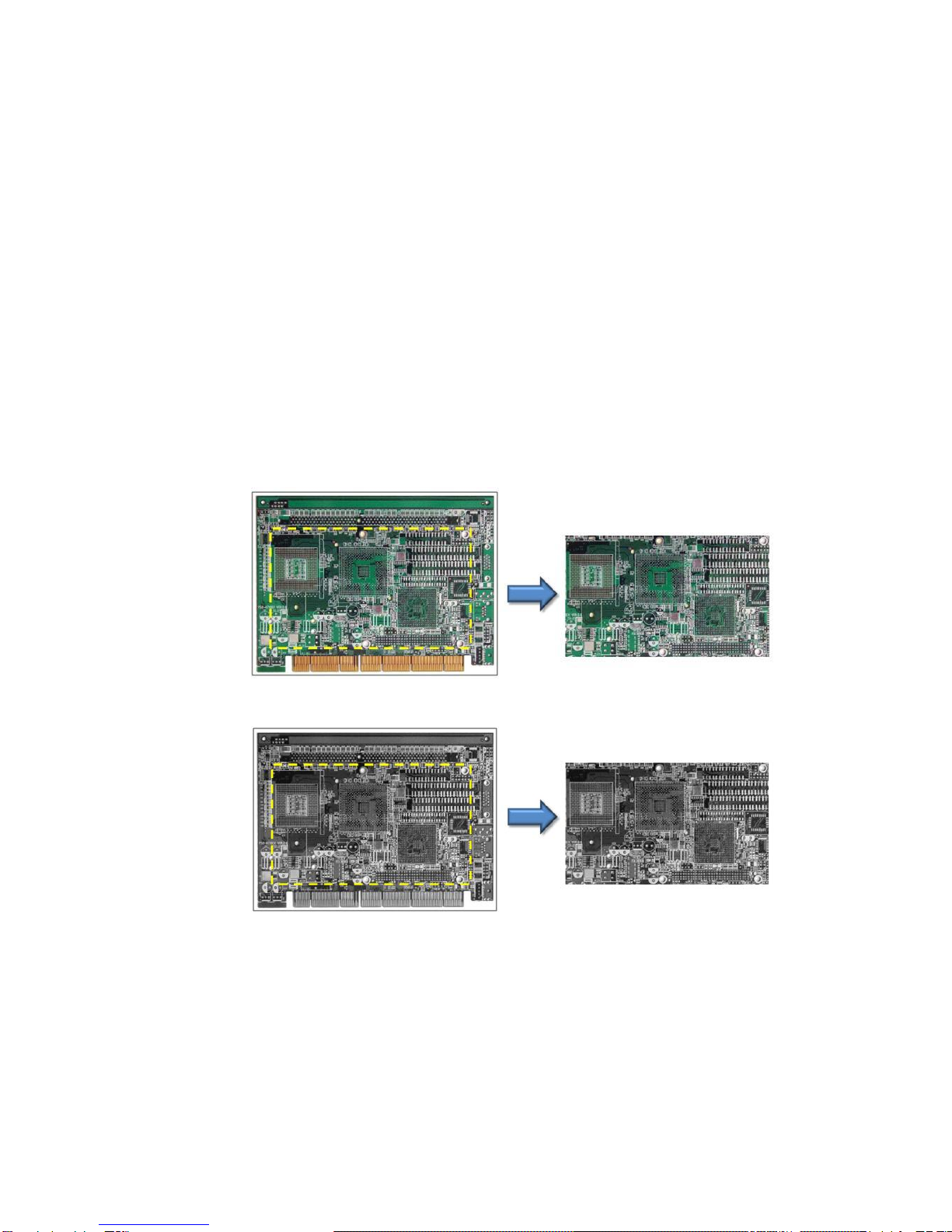
calculations, listed below.AOI (Area of Interest)
The AOI (Area of Interest) function allows users to select an area of interest, for the camera‟s
CCD array to specifically read, display, and transmit.
Sparrow IMS camera offers include Mono 8-bit, Mono 16-bit and RGB 24-bit in total 3 color
formats and each color format will generate difference data structure.
Mono 8-bit: It‟s black and white image data and grayscale present in 8-bit depth, each
pixel size is one byte.
Mono 16-bit: It‟s black and white image data and grayscale present in 16-bit depth, each
pixel size is two bytes.
RGB 24-bit: its color image and construction by red, green and blue individually color data,
each pixel size is three bytes.
Figure 1-1 Color AOI Acquisition
Figure 1-2 Mono AOI Acquisition
Before using AOI function, please make sure AOI mode is selected in Video Mode. NO
activated if AOI is not selected.
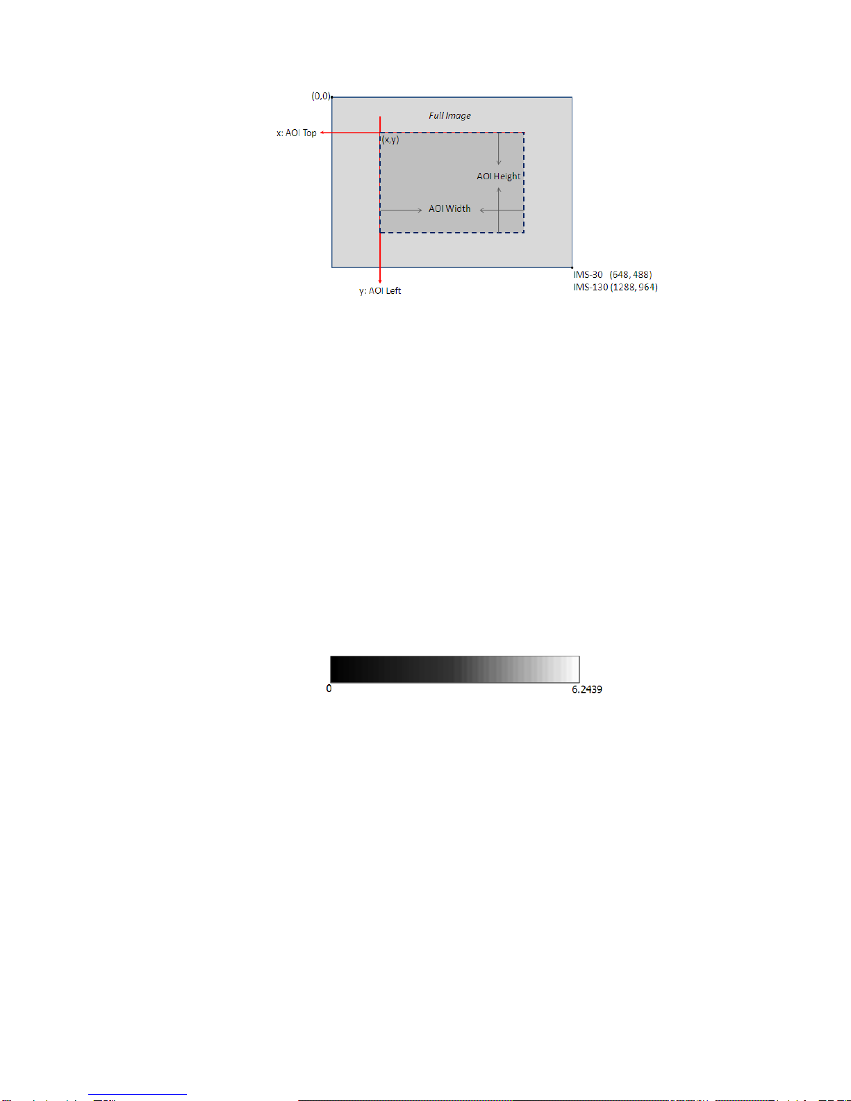
The AOI function will required the values of Left, Top, Width and Height to specify AOI region.
Due the AOI image data structure, so user must to follow the possible values of AOI definition
as below.
- 8 -
AOI Left: The value must be 2*N, when N is an integer
AOI Top: The value must be 2*N, when N is an integer
AOI Width: The value must be 8*N, when N is an integer
AOI Height: The value must be 2*N, when N is an integer
AOI Left + AOI Width must be under the total width of Full Image
AOI Top + AOI Height must be under the total height of Full Image
Also, frame rate can be changed in AOI function. Frame rate is automatically adjusted into
range of camera if frame rate setting over range of camera.
1.4.2Brightness
All image data luminance will be changed by adjusting Brightness. Sparrow IMS camera offers
adjustable function of Brightness and absolute value range from 0.0 ~ 6.2439%. Default value of
Brightness is 3.997803.
1.4.3Sharpness
All image data contrast will be changed by adjusting Sharpness. Sparrow IMS camera offers
adjustable function of Sharpness and range from 0 ~ 4095. Default value of Sharpness is 2048.
1.4.4White Balance
Sparrow IMS CCD camera camera are using the Bayer tiling in the CCD for the color pixel data.
White Balance function is able to work well on color correction to deal with differing lighting
conditions.

- 9 -
The White Balance scheme outlined in the IIDC specification states that blue and red are
adjustable but the green is not. White Balance function will offer gain value of red and blue for
adjusting the color balance of the camera and range from 0 ~ 1024. Default value of gain value of
red of White Balance is 600, while blue is 840.
1.4.5Hue
All color image space can be changed by adjusting Hue function. Sparrow IMS camera offers
adjustable function of Hue and absolute value range from -180.0 ~ 179.912, and default value is
0.
1.4.6Saturation
All image date color purity can be changed by adjusting Saturation function. Sparrow IMS
camera offers adjustable function of Saturation and absolute value range from 0.0 ~ 399.902,
and the default value is 136.9141.
- 10 -
1.4.7Gamma and LUT
Gamma and LUT (Lookup Table) function will be changes
image data converted structure. Once change gamma value
then the lookup table data structure will be change
immediately. Sparrow IMS offers adjustable function of
gamma and absolute value range from 0.50 ~ 3.99902, and
the default value is 0.999.234.
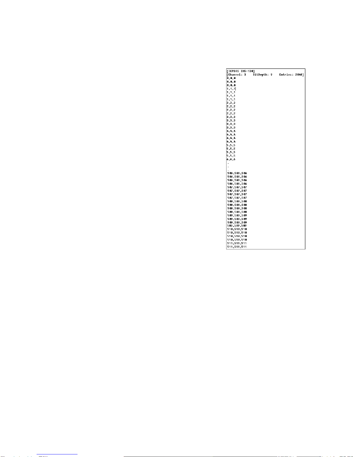
Sparrow IMS camera support three 11-bit input lookup table
that produce 9-bit outputs. Three channels can be
individually for red, green and blue color data output, or
equalized value for monochrome color format.
It can be used to apply a non-linear mapping of the image
result. User can used this function to get Lookup Table file of
the camera. This file is standard text file format and user can
open or modify Lookup Table content very easily.
By default, when gamma value =1.0, which yields a linear
response then gamma functionality will be OFF and failed to
change the Lookup Table content.
1.4.8Gain
Gain function will be changes over all image data, and its adjustable level of amplification of the
camera signal. Sparrow IMS camera offers adjustable function of Gain and absolute value range
from -6.26386 ~ 24.0001. However when gain is increased in an image, one must also take into
consideration the addition of significant noise. Therefore keep the Gain value in 0 is strong
recommend by default.
1.4.9Shutter (Exposure)
Shutter function is adjustable level of shutter speed for the exposure of image integration time.
However the camera shutter integration time must be less than the frame rate. Therefore the
Sparrow IMS camera offers adjustable function of Shutter speed and range from 4.65us ~
133ms.

- 11 -
1.4.10 Trigger Control
Sparrow IMS camera offers two Trigger control mode, included Standard Trigger Mode and Bulb
Shutter Mode. The trigger control resource could be come from hardware or software.
Sparrow IMS camera designs the pin 1 of GPIO interface which dedicated for physical external
hardware trigger resource. It is opto-isolated open collector circuit designed (For detail
schematic, please refer 1.4.11) and input voltage range from +3.3VDC to +30VDC in maximum
input 8.3mA.
Standard Trigger Mode
The Standard Trigger Mode offers the control resource can be come from hardware or
software. If user selects the trigger resource from software, and user be able to use camera
acquire image by programming software trigger.
The trigger signal can be chosen by rising edge or falling edge when user selected the
trigger resource from hardware.
Figure 1.4.10.1 Standard Trigger by Rising Edge
Figure 1.4.10.2 Standard Trigger by Falling Edge
Bulb Shutter Mode
The Bulb Shutter Mode offers the control resource can be come from hardware or software.
If user selected the trigger resource from software, and then user is able to use camera
acquire image by programming software trigger.
The camera exposure time will be base on the trigger signal duration, and the trigger signal
can be choose by rising edge or falling edge when user selects the trigger resource from
hardware.

- 12 -
Figure 1.4.10.3 Bulb Shutter Trigger by Rising Edge
Figure 1.4.10.4 Bulb Shutter Trigger by Falling Edge

- 13 -
1.4.11 GPIO (General Purpose Digital Input and Output)
The Sparrow IMS camera offers the GPIO interface and pin define as below.
8-Pin Hirose GPIO interface
Pin No.
Define
Description
1
GPIO0
Opto-isolated input, Default for Trigger Input
(+3.3V to +30V), Input delay time:4us
2
GPIO1
Opto-isolated output, Default for Strobe Output,
Drive strength:25mA at 30V
3
GPIO2
Bi-directional Input / Output
4
GPIO3
Bi-directional Input / Output
5
IGND
Ground pin for bi-direction IO, Vext, +3.3V
6
GND
Ground pin for Opto-isolated IO pins
7
VEXT
Allows the camera to be powered externally
8
+3.3V
Power external devices up to 150mA
1.1.1.1 GPIO0 (Opto-Isolated Input) Circuit
The figure below shows the schematic for the opto-isolated input circuit.
Logical o input voltage: 0VDC to +1DC (voltage at OPTO_IN)
Logical 1 input voltage: +1.5VDC to +30VDC(voltage at OPTO_IN)
Maximum input current:8.3mA
Behavior between 1VDC and 1.5VDC is undefined and input voltages between those
values should be avoided.
Input delay time:4us
- 14 -
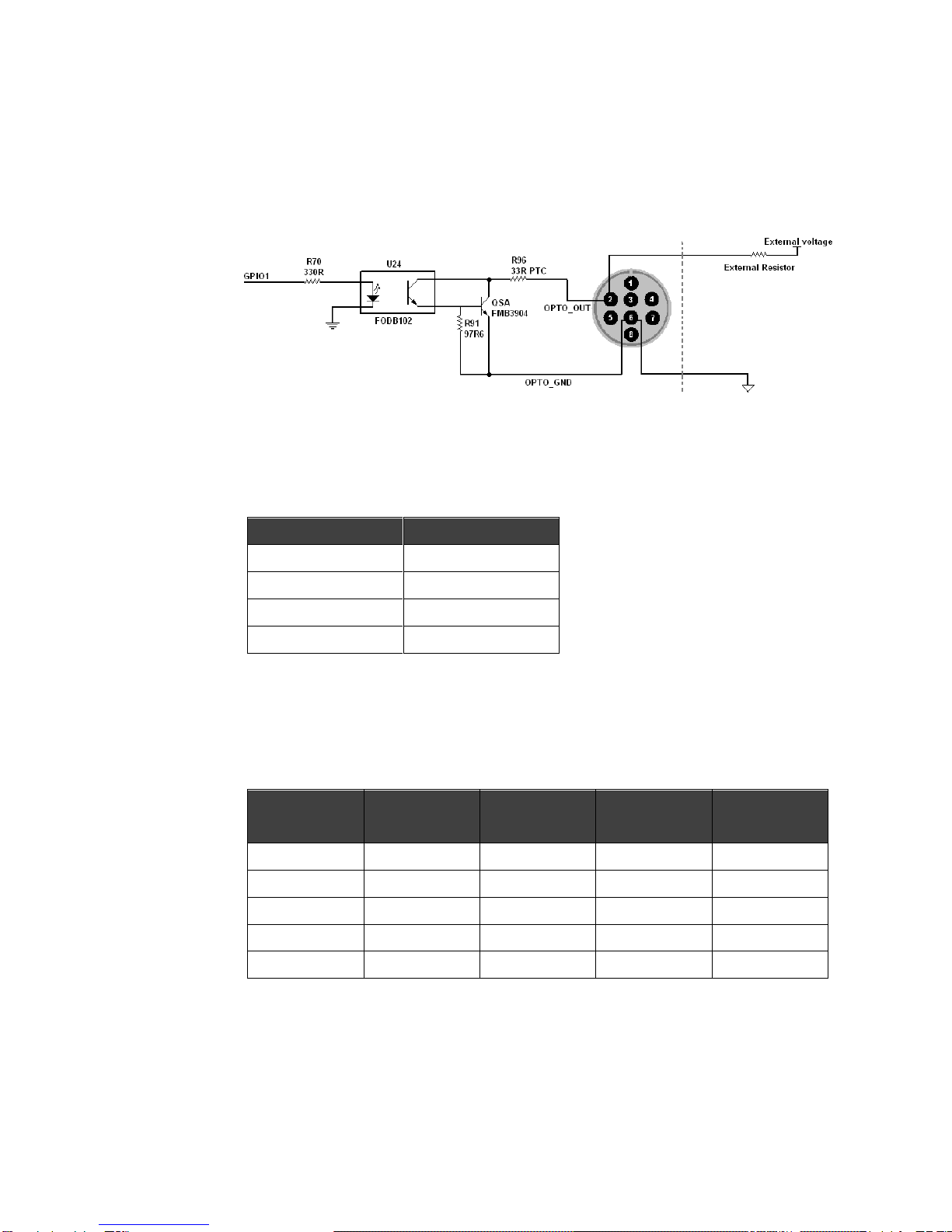
1.1.1.2 GPIO1 (Opto-Isolated Output) Circuit
The figure below shows the schematic for the opto-isolated output circuit. The maximum
current allowed the opto-isolated output circuit is 25mA (limit by PTC resistor), and the
output impedance is 140 Ohm.
Response Time
The following table lists the switching times for the opto-isolator in the output pin, assuming
an output VCC of 5V and 1K Ohm resistor.
Parameter
Value
Delay Time
9us
Rise Time
16.8us
Storage Time
0.52us
Fall Time
2.92us
Sample voltage / Resistor combinations
The following table lists several external voltage and resistor combinations that have been
tested to work with the GPIO1 opto-isolated output.
External Voltage
External Resistor
OPTO_OUT
Voltage
OPTO_OUT
Current
Short Current
3.3V
1K Ohm
0.56V
2.7mA
43mA
5V
1K Ohm
0.84V
4.2mA
47mA
12V
2.4K Ohm
0.91V
4.6mA
21.5mA
24V
4.7K Ohm
1.07V
5.1mA
13.5mA
30V
4.7K Ohm
1.51V
13.3mA
6.1mA
- 15 -
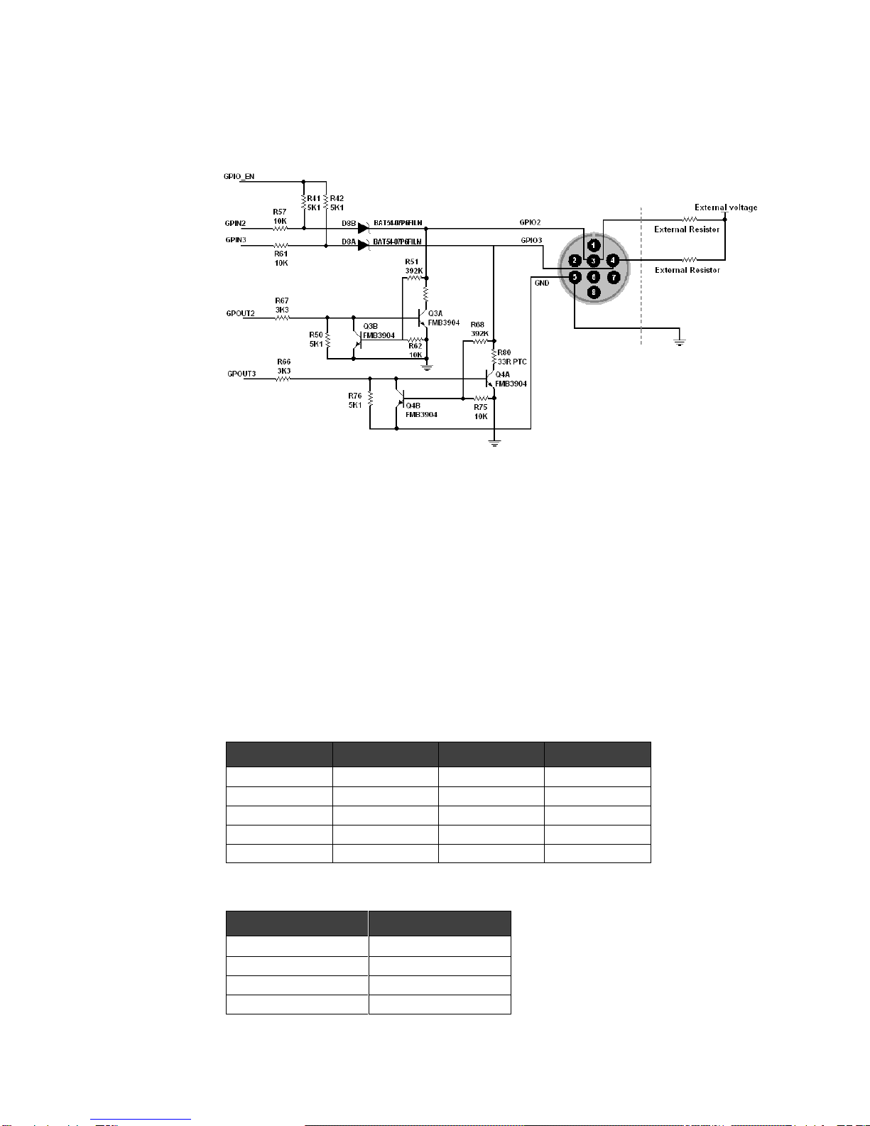
1.1.1.1 GPIO2 and GPIO3 (Bi-Direction) Input / Output Circuit
The figure below shows the schematic for the GPIO2 and GPIO3 bi-directional input or
output circuit.
Input Side
Logic 0 input voltage: 0VDC TO +0.5VDC (voltage at GPIO2/GPIO3)
Logic 1 input voltage: +1.5VDC to +30VDC (voltage at GPIO2/GPIO3)
Behavior between 0.5VDC and 1.5VDC is undefined and input voltages
between values should be avoided
To avoid damage, connect the GND pin first before applying voltage to the GPIO
line.
Output Side
The maximum output current through the bi-directional circuit is 25mA(limit by PTC resistor)
and the output impedance is 40 Ohm. The following table lists several external voltage and
resistor combinations that have been tested to work with the bi-directional GPIO when
configure as output.
External Voltage
External Resistor
GPIO2/3 Voltage
Short Current
3.3V
1K Ohm
0.157V
62mA
5V
1K Ohm
0.218V
45mA
12V
1K Ohm
0.46V
23mA
24V
1K Ohm
0.86V
7.5mA
30V
1K Ohm
0.966V
0.1mA
The following table lists the switching times for a standard GPIO pin, assuming an output
VCC of 5V and 1K Ohm resistor.
Parameter
Value
Delay Time
0.28us
Rise Time
0.06us
Storage Time
0.03us
Fall Time
0.016us

- 16 -
1.4.12 Strobe Control
This feature allows users to enable and parameterize up to three strobe light control
output signals. The signals are designated as Strobe 1, Strobe 2, and Strobe3. Each
strobe signal can be set to active high or active low by logical value, please refer to
section 6, “Function Library”, for command definitions.
The strobe is determined by a combination of two values; Delay Value and Strobe
Duration-- both range from 0 sec. ~ 10 sec.
The Strobe delay will determine the time between the start of image exposure and when
the strobe signal changes state as show in Figure 1-13.
Figure 1-13: Strobe Signal
1.4.13 Save Camera Configuration
Sparrow IMS camera provides a function on save camera configuration to help customer to
setting and maintain camera parameters easily. User can use EzView Pro Utility to real-time
adjust camera parameters and save the configure setting into the camera or local computer. The
configure file can be upload to any Sparrow IMS camera.
1.4.14 Data Flash Control
Sparrow IMS camera offers 64K bytes Data Flash memory for customer to save or restore
camera settings and AES project encryption register code. The address of data flash can be read
and write, range from 0x0 ~ 0xFFFF. Keep the camera power sustained when written data into
the Data Flash; otherwise the data may loose due the camera power off.

- 17 -
1.4.15 Software AES Project Encryption
Sparrow IMS camera offer an software AES project encryption function. The system designer
can use this function to generated unique security key to protected the copy right of their system.
The IMS_Get_CameraInform function can get the unique hardware information of the camera,
and call AES_GET_REG function to set 16bytes AES key then will get 16bytes AES project
encryption register code.
Normally the AES project encryption register code can be save into any device as customer
need. Also user can write the register code into the Data Flash of the camera via
IMS_Write_DataFlash function. The system designer can use IMS_Read_DataFlash to get this
code to check whole system condition before system operation.
1.4.16 Test Pattern
Sparrow IMS cameras offer an internal generated test pattern for testing camera
transmission. The test pattern will show a gray diamond pattern image when user
enable the Test Pattern function and start acquired images.

- 18 -
1.5 Spectral Response
Below is the spectral response curve of Sparrow IMS camera CCD sensor and excludes the Lens and
lighting source characteristics.
IMS-130 Monochrome Mode
Spectral Sensitivity
IMS-130 Color mode
Spectral Sensitivity

- 19 -
1.6 Benchmarks
Sparrow IMS camera is able to connect to IEEE 1394a (400Mbps) or IEEE 1394b (800Mbps) IEEE
interface port. The bandwidth of IEEE interface port may decide the frame rate of camera acquisition,
and also the sharing connected structure may reduce camera acquisition speed.
The following benchmark information is based on the IEEE 1394 port bandwidth condition and user
may get the reference for system performance consideration.
1.6.1 Standard Video Mode
Resolution
Video Mode
1394a
1394b
640 x 480
MONO8 - 30FPS
○
○
MONO8 - 15FPS
○
○
MONO8 - 7.5FPS
○
○
MONO16 - 30FPS
○
○
MONO16 - 15FPS
○
○
MONO16 - 7.5FPS
○
○
RGB - 30FPS
○
○
RGB - 15FPS
○
○
RGB - 7.5FPS
○
○
800 x 600
MONO8 - 30FPS
○
○
MONO8 - 15FPS
○
○
MONO8 - 7.5FPS
○
○
MONO16 - 30FPS
○
○
MONO16 - 15FPS
○
○
MONO16 - 7.5FPS
○
○
RGB - 30FPS
×
○
RGB - 15FPS
○
○
RGB - 7.5FPS
○
○
1024 x 768
MONO8 - 30FPS
○
○
MONO8 - 15FPS
○
○
MONO8 - 7.5FPS
○
○
MONO16 - 30FPS
×
○
MONO16 - 15FPS
○
○
MONO16 - 7.5FPS
○
○
RGB - 15FPS
×
○
RGB - 7.5FPS
○
○

- 20 -
Resolution
Video Mode
1394a
1394b
1280 x 960
MONO8 - 30FPS
×
○
MONO8 - 15FPS
○
○
MONO8 - 7.5FPS
○
○
MONO16 - 30FPS
×
×
MONO16 - 15FPS
×
○
MONO16 - 7.5FPS
○
○
RGB - 15FPS
×
○
RGB - 7.5FPS
○
○
1.6.2 AOI Video Mode
When set the camera Video Mode in VM_AOI, the real acquisition speed will base on the IEEE 1394
bandwidth, video format and resolution for the frame rate result. Normally IEEE 1394a host chipset
bandwidth can reach about 30MB/s, and IEEE 1394b host chipset can reach bandwidth around
60MB/s.
By using more Sparrow cameras in the system, user must consider if here is enough bandwidth of
IEEE 1394, or choose multiple host chipsets interface card for it.
IEEE 1394 Bandwidth
1394a S400
1394b S800
Model No.
IMS-130
IMS-130
640 x 480_Mono8
52fps
52fps
640 x 480_Mono16
50fps
52fps
640 x 480_RGB
34fps
52fps
800 x 600_Mono8
44fps
44fps
800 x 600_Mono16
32fps
44fps
800 x 600_RGB
22fps
36fps
1024 x 768_Mono8
36fps
36fps
1024 x 768_Mono16
20fps
36fps
1024 x 768_RGB
13fps
24fps
1280 x 960_Mono8
26fps
30fps
1280 x 960_Mono16
13fps
31fps
1280 x 960_RGB
8.5fps
18fps
1.6.3 ICP DAS IEEE 1394 products
Model No.
IEEE 1394 Bandwidth
VISION BOX Series (VB-115/VB-216)
400Mbps x 2 ports
IOI-4601-21 2-CH IEEE 1394a interface card
400Mbps x 2 ports
Table of contents


