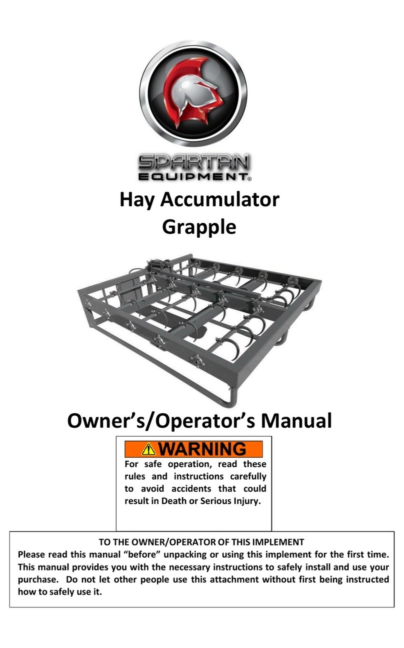
Spartan Equipment Mini Pick-Up Broom User manual

Mini Skid Steer Loaders
And
Mini Track Loaders
For
Mini Pick-Up Broom
Operator's Manual
Maintenance and Parts Information
Do not use or operate this machine until this manual has been read and
understood.
Read the Operation
&
Maintenance Manual entirely. When you see this
symbol, the subsequent instructions and warnings are serious - follow
without exception. Your life and the lives of others depend on it!

IMPORTANT
If this machine is used by an employee or is loaned o
r
rented to others, make certain that the operator(s) prior to
operating:
• Is instructed in safe and proper use.
Reviews and understands the operation and
maintenance manual(s) pertaining to the machine.
Remember, the operator is responsible for the safe
operation and maintenance of the machine. Most
accidents can be prevented. Good safety practices not
only protect you, but also the people around you.
2

TABLE OF CONTENTS
FOREWORD 4
SAFETY 5
SERIAL NUMBER/DECAL LOCATION 6-7
USERS INSTRUCTIONS FOR MOUNTING THE MINI PICK-UP BROOM 8-9
OPERATING THE MINI PICK-UP BROOM 10-11
ROUTINE MAINTENANCE 12-15
PARTS INFORMATION 16-18
GENERAL SPECIFICATIONS 19
REFERENCE INFORMATION
Write the correct information for YOUR MINI PICK-UP BROOM in the spaces below. Always use these
numbers when referring to your MINI PICK-UP BROOM.
MINI PICK-UP BROOM Serial Numbe
r
3

denotes a hazard
between DANGER and
To The Owner/Operator: FOREWORD
DO NOT use or operate this machine
understood. If you require additional
Spartan Equipment.
Operation and Maintenance Manuals are written to
give the owner/operator instructions on the safe
operation and maintenance of the product. For your
safety and the safety of other persons, you must not
operate, service, inspect or otherwise handle this
equipment before you have reviewed and understood
the Operation and Maintenance Manual(s) pertaining
to the Spartan Equipment™ Mini Pick-Up Broom(also
referred to as "attachment") and the mini skid steer
loader/mini track loader (hereafter referred to as
"loader").
Throughout this manual reference may be made to
the left hand (LH) or right hand (RH) side. These
terms are used as viewed from the operator's station
facing front.
In order to get the optimum performance and
efficiency that has been designed into the attachment,
read this manual thoroughly before setting-up,
operating, or performing maintenance procedures on
the machine.
It is the responsibility of the user to read the
operator’s manual and comply with the safety
Instructions, operating instructions and maintenance
guidelines set forth in this manual.
The user is responsible for inspecting the loader and
attachment daily, and for having parts repaired or
replaced when continued use would cause damage,
excessive wear to other parts or make continued
operation unsafe.
The signal words CAUTION, WARNING, or DANGER
are used to indicate degree of hazards and to warn
against unsafe practices that may cause personal
injury and are used with appropriate safety
instructions. These signal words are not to be
ignored; your safety is involved.
until this manual has been read and
information, contact your Dealer or
CAUTION: denotes a general reminde
r
of good safety practices or directs
attention to unsafe practices.
WARNING:
intermediate
CAUTION.
DANGER: denotes the most serious
"hazard.
The word NOTE is used to convey information that is
out of context with the manual text; special
information such as specifications, techniques,
reference information, and other information of a
supplementary nature.
The word IMPORTANT, is used in the text when
immediate damage will occur to the machine due to
improper technique or operation. IMPORTANT will
apply to the same information specified by NOTE,
only of an immediate and urgent nature.
Spartan Equipment cannot anticipate every possible
circumstance that might involve potential hazard. The
safety messages found in this manual and on the
machine are therefore not all inclusive. If an operating
procedure, tool device, maintenance or work method
not specifically recommended is used; you must
satisfy yourself that it is safe for you and others. You
must also ensure that the machine will not be
damaged or made unsafe by the procedures you
choose.
4

SAFETY
Whenever you see this symbol, it means Attention!
Become Alert! Your Safety is involved.
Failure to obey warnings or instructions can cause
personal injury or death.
Operating instructions must be given to everyone before operating this machine and at least once a year
thereafter in accordance with OSHA regulations.
General Safety Instructions
Read the operators manual for the loader to
become totally familiar with the controls and
instruments. Know how to stop all equipment
operation in case of emergency.
Avoid the possibility of personal injury and/or
machine damage. NEVER exceed the maximum
recommended input power or speed specifications
for the attachment.
Check and be sure all operating controls are in
neutral before starting the engine.
Disengage hydraulic drive, lower the attachment to
rest flat on the ground, stop engine, set park brake,
and wait for all motion to stop before leaving the
operator's station for any reason.
WARNING: Before adjusting, or servicin
g
the unit, stop the engine and relieve al
l
hydraulic pressure by opening the contro
l
valve.
Keep all shields, guards, and covers in place.
Stay clear of the attachment when unit is running.
NEVER make adjustments, lubricate, or perform
any service on the machine while it is running.
Keep people at least 10 feet (3m) away from
machine when machine is running.
NEVER operate near embankments or terrain that
is so steep that rollover could occur.
NEVER allow children or untrained persons to
operate.
DO NOT permit riders on equipment.
Use adequate safety warning lights and devices as
required by local regulations.
Obey all local laws and regulations regarding
machine operation on public property.
The machine is designed for sweeping dirt and
small debris on hard packed surfaces only. NE
V
ER
use this machine for other materials.
Do not modify equipment or add attachments that
are not approved by Spartan Equipment.
Remember, YOU are responsible for the safe
operation and maintenance of the equipment. Most
accidents can be prevented. Good safety practices
not only protect you, but also the people around
you.
Wear Protective Equipment
Protective clothing and equipment should be worn.
Wear clothing and equipment appropriate for the
job. Avoid loose fitting clothing.
Prolonged exposure to loud noise can cause
hearing impairment or hearing loss. Wear suitable
hearing protection such as earmuffs or earplugs.
Operating equipment safely requires the full
attention of the operator. Avoid wearing radio
headphones while operating equipment.
A
void High Pressure Fluids Hazard
Escaping fluid under pressure can penetrate the
skin causing serious injury.
Avoid the hazard by relieving the pressure before
disconnecting hydraulic lines.
Use a piece of paper or cardboard, NOT BODY
PARTS, to check for suspected leaks. Wea
r
protective gloves and safety glasses or goggles
when working with hydraulic systems.
If an accident occurs, see a doctor immediately.
Any fluid injected into the skin must be surgically
removed within a few hours or gangrene may
result.
5

SERIAL NUMBER AND SAFETY DECAL LOCATIONS
Serial Number Location:
It
is important to refer to the serial number of the attachment when making repairs or ordering parts. Early or late
r
models (identification made by serial number) may use different parts, or it may be necessary to use different
procedures in doing a specific operation.
6

SERIAL NUMBER AND SAFETY DECAL LOCATIONS
7

USER'S INSTRUCTIONS FOR MOUNTING THE MINI PICK-UP BROOM
A
fter uncrating the attachment, use the following procedure to mount the attachment to the loader.
Instructions for mounting to a ride-on
mini skid loader:
1. Use the step, safety treads, and grab
handles to get on and off the loader.
2. Sitting in the operator's seat, lower seat bar
and fasten the seat belt and with the
controls in a neutral position, start the
engine.
3. Drive the loader to the rear of the
attachment. Put the loader quick attach
coupler into the attachment mounting
bracket.
4. Tilt the loader coupler backward a small
amount until it is fully engaged in the
attachment mounting bracket.
5. Stop the engine and engage the park brake.
6. Exit the loader and secure the coupler
locking mechanism that locks the
attachment to the loader.
WARNING: Coupler wedges or pins
must extend through the holes in th
e
attachment mounting plate. Levers
must be fully down and locked.
Failure
to
secure wedges or pins can
allow attachment
to
come off and cause
injury or death.
Instructions for mounting to a walk-
behind mini skid loader:
1. Standing at the operator's station with the
controls in a neutral position, start the
engine.
2. Drive the loader to the rear of the
attachment. Put the loader quick attach
coupler into the attachment mounting
bracket.
3. Tilt the loader coupler backward a small
amount until it is fully engaged in the
attachment mounting bracket.
4. Stop the engine and engage the park brake.
5. Walk to the front of the loader and secure
the coupler locking mechanism that locks
the attachment to the loader.
WARNING: Coupler wedges or pins
must extend through the holes in th
e
attachment mounting plate. Levers
must be fully down and locked. Failur
e
to
secure wedges or pins can
allow attachment
to
come off and
cause injury or death.
8

USER'S INSTRUCTIONS FOR MOUNTING THE MINI PICK-UP BROOM
NOTE: Attachment is shipped with 8FJX (3/4
'
Female JIG Swivel) fittings on the ends of the lea
d
hoses.
7. Connect the hydraulic quick couplers from the
Mini Pick-up Broom to the loader. Be sure to
thread the hoses through the hose holder on
the loader. Bungee straps can be used as an
alternate method of securing the hoses.
NOTE: Make sure the quick couplers are full
y
engaged. If the quick couplers do not fully engage,
check to see that the couplers are the same size
and brand. Do not force the quick couplers
together.
If the quick couplers will not connect togethe
r
due to thermal expansion of the fluid in the
hoses, stop the engine and activate the auxiliary
hydraulic control to relieve the pressure.
NOTE: See the loader's operation and
maintenance manual.
8. Mounting is now complete and you are ready to
use the Mini Pick-up Broom. Use reverse order
of above instructions to dismount the Mini Pick-
up Broom from the loader.
NOTE: Make sure the hoses are properly routed
to fit your specific loader. If the hoses are not
routed correctly, hoses may get pinched or rub on
tires. Be sure to check the hose routing through the
full range of intended motion of the attachment
before operating it.
More than one routing may be acceptable
depending on the loader. Pick the routing that best
suits your loader.
PROPER HOSE ROUTING IS THE
RESPONSIBILITY OF THE OWNER AND/OR
OPERA TOR. PINCHED OR STRETCED HOSES
ARE NOT COVERED UNDER WARRANTY.
9

OPERATING THE MINI PICK-UP BROOM
WARNING:
DO NOT operate from any position other than the operator's station .
DO NOT
permit riders.
o
With the operator at the operator's station, the seat
belt fastened and the seat bar lowered (if so
equipped), start the engine.
The Mini Pick-up Broom is not designed to be
used on loaders with a Rated Operating
Capacity (ROC) of more than 1000 pounds.
WARNING: AVOID INJURY OR
DEATH.
Keep people at least 10 feet
(3m) away from machine when
machine is running.
A
void excessive down-pressure as this will result in
premature bristle wear. It is recommended to maintain
a 2.0-4.0 inch (51-102 mm) contact area.
IMPORTANT:
Vary travel, engine, and bristle
speeds for all sweeping conditions.
Forward Travel
For normal sweeping, position bucket cutting edge
slightly above the ground, activate hydraulics for the
bristles (rotating counter clockwise, or away from the
operator), and move the Mini Pick-up Broom forward.
This also helps to avoid scratching of the surface
being swept.
NOTE:
For steering lever functions, refer to your
loader's operation and maintenance manual.
IMPORTANT:
When turning at
a
high rate of speed,
raise the front wheel of the Mini Pick-up Broom off the
ground. Excessive speed can damage the caste
r
assembly.
10

2. OPERATING THE MINI PICK-UP BROOM
Backward Travel
If the debris is packed on the surface or to pick up
heavier/larger material, position bucket cutting edge
flat on the ground, activate hydraulics for the bristles
(rotating clockwise, or towards the operator), and
move the Mini Pick-up Broom backward. The Mini
Pick-up Broom cutting edge will scrape the debris
while the bristles will sweep the debris off the surface
and into the bucket.
NOTE: For steering lever functions, refer to your
loader's operation and maintenance manual.
When the debris starts falling out of the bucket • back
onto the surface, this is an indication that the bucket is
full and needs to be dumped.
Disengage the hydraulics, raise the Mini Pick-up
Broom above the ground and keeping it low to the
ground, move the loader to the dumping area.
Raise the loader boom and tip forward in order to
empty the bucket of debris.
NOTE: It may be necessary to run the Mini Pickup
Broom while dumping to remove the debris from
inside and around the bristles.
WARNING: AVOID INJURY OR
DEATH.
Never lift the loade
d
Mini Pick-up Broom more than 3
feet (1m) off the ground while
transporting,
as
tipping ma
y
occur.
11

ROUTINE MINI PICK UP-BROOM MAINTENANCE
It is the operator's responsibility to make daily inspections of the loader and attachment for damage, loose bolts, fluid leaks, or
anything else that could cause a potential service or safety problem. Preventive maintenance is the easiest and least expensive
type of maintenance.
IMPORTANT: Bolts and set screws can loosen after initial usage. After the first hour
of
operation check al
/
bolts and set screws.
WARNING: Lower the attachment
to
the ground, shut down the engine, relieve the hydrauli
c
pressure
to
the attachment, wait for all motion
to
stop, and set park brake before leaving the
operator's station
to
perform service of any kind.
Use No. 2 lithium base gun grease when lub-
ricating all Mini Pick-up Broom grease fittings.
Grease the 2 zerks on the caster wheel after
every 8 hours of operation.
WARNING: These are require-
ments. It is the responsibility o
f
the owner/operator
to
make sure
the attachment is serviced
on a daily basis. Improper
maintenance can cause
extensive damage
to
the
attachment and/or you
r
equipment.
12

ROUTINE MINI PICK-UP BROOM MAINTENANCE
Replacing Brush Sections
Remove the side rubber shields from both sides on
the Mini Pick-up Broom.
Remove the (2) end plate mounting bolts and nuts
(on each side), retain for later assembly.
NOTE: The motor and hex drive block will be
removed with the end plate.
Raise the body section with a hoist and secure with
saw horses or jack stands.
Carefully remove the brush head assembly.
13

ROUTINE MINI PICK-UP BROOM MAINTENANCE
Replacing Brush Sections (continued)
Remove the bearing retaining bolt and washer.
Loosen the set screws on the bearing assembly and
slide off the bearing/endplate assembly.
Remove the (3) bolts holding the brush retainer to the
brush tube. Remove the brush retainer.
Remove old brush sections.
Install new brush sections by doing the following:
a. Number the ribs on the core as 1, 2, and 3.
b. First slide (1) flat brush section on the core,
making sure that the drive pins are on either side
of a core rib.
c. Slide on (1) spacer.
d. Slide the first "wavy" brush section on (face up),
so that the drive pins are around the number 1
core rib.
e. Slide the second "wavy" brush section (face
down) on the number 2 core rib.
NOTE: every other brush section will need to
be "flipped" so that the high spots hit each
other.
f. Slide the third "wavy" brush section (face up) on
the number 3 core rib.
g. Repeat until all "wavy" brush sections are
installed, making sure to alternate the core ribs
used.
NOTE: If you have a broom with poly/steel
combination brushes, be sure to alternate poly
and steel when assembling.
h. Slide on the remaining spacer.
i. Lastly, slide on the remaining flat brush section on
the end of the core.
NOTE: The brush stack does not need to be
flush with the end of the arbor. It may be
higher or lower depending on how each brush
section is formed. If the stack is high, just
compress it when reattaching the brush
retainer. If it is low, it will spread out when the
arbor is laid down.
14

ROUTINE MINI PICK-UP BROOM MAINTENANCE
Replacing Brush Sections (continued)
Reattach the brush retainer.
Slide on the bearing/end plate assembly. Tighten
the set screws on the bearing assembly.
Install the bearing retaining bolt and washer.
Move the arbor and brush assembly into the bucket
housing. Lower the upper body housing by lowering
the hoist. Make sure the end plates and rubber side
shields are in place for replacement.
Line up the bolt holes and secure the end plates to
the upper body assembly. Slide the motor and end
plate assembly into the brush core, lining up the hex
drive block into the hole inside the brush core. Be
sure to adjust the arbor height to ensure a 2.0-4.0
inch (51-102 mm) contact area, this is done by
positioning the rear end plate bolts in the
appropriate hole on the adjustment bars. With new
bristles, this is normally the highest hole.
15

MINI PICK-UP BROOM PARTS INFORMATION
16

MINI PICK-UP BROOM PARTS INFORMATION
ITEM QTY PART NO. DESCRIPTION STOCK NUMBER
1 1 318403 BRACKET PIVOT RH
2 1 318404 BRACKET PIVOT LH
3 2 318427 SHEILD RUBBER SIDE
4 1 400331 BODY PICK UP BROOM 48 W/A
8 1 400343 SHIELD RUBBER FRONT 48
10 1 318499 CASTER ASSEMBL Y 8 X 2
11 1 400000 MOUNT FRAME TORO MINI W/A OPTIONAL MOUNT PACKAGE
1 400001 MOUNT FRAME ASV MINI W/A OPTIONAL MOUNT PACKAGE
1 400002 MOUNT FRAME BC MINI W/A OPTIONAL MOUNT PACKAGE
1 300283 MOUNT FRAME UNIV MINI W/A OPTIONAL MOUNT PACKAGE
12 6 37214 NUT HEX
-1/2 -
UNC - GR 5 - REV LOCK OPTIONAL MOUNT PACKAGE
13 6 13207 BOLT HEX -
1/2
X
1-1/4 -
UNC - GR 5 OPTIONAL MOUNT PACKAGE
15 1 400349 SHIELD RUBBER TOP 48
20 1 400050 MINI LO-PRO BUCKET W/A
25 2 400325 BUSHING 1.00 X .56 X 1.00 Z
26 2 36110 NUT HEX FULL
1/2 -
UNC - GR 5
27 2 313321 WASHER .531D X 1.3750D X .199
28 8 37214 NUT HEX
1/2 -
UNC - GR 5 - REV LOCK
29 2 13212 BOLT HEX
1/2
X 2.25 - UNC - GR 5
42 10 37212 NUT HEX
3/8 -
UNC - GR 5 - REV LOCK
43 6 103116 BOLT HEX
3/8
X 1 - UNC - GR 5
45 4 103879 BOLT HEX
3/8
X 1.5 - UNC - GR 5
47 8 33220 WASHER FLAT FENDER
3/8
X
1-1/2
48 16 32467 BOLT FLG THRD RLNG
3/8
X
3/4 -
UNC - GR 5
49 2 33636 WASHER LOCK
1/2"
50 2 13360 BOLT HEX
3/4
X 1.75 - UNC - GR 5
51 4 33632 WASHER LOCK 0.75 - GR 5
52 2 13365 BOLT HEX
3/4
X 3 - UNC - GR 5
53 2 318277 BOL T CARRIAGE SHORT NECK
1/2
X 1.50 - UNC - GR 5
55 6 13205 BOLT HEX
1/2
X 1 - UNC - GR 5
58 1 400111 CUTTING EDGE
1/2
X 4 X 49.5 OPT BOLTON CUTTING EDGE
60 1 400337 FLAT FRONT 48 PAINTED (400344 UNPAINTED)
61 5 33636 WASHER LOCK
1/2
OPT BOLT ON CUTTING EDGE
63 5 36110 NUT HEX REG
1/2
NC GR 5 OPT BOLT ON CUTTING EDGE
65 5 22643 BOLT PLOW
1/2
X 1.5 - UNC - GR 5 OPT BOLTON CUTTING EDGE
17

MINI PICK-UP BROOM PARTS INFORMATION
ITEM QTY PART NO. DESCRIPTION STOCK NUMBER
7 1 318459 DRIVE BLOCK HEX 1" BORE-SNAP RING INCLUDED
17 2 203741 FLANGET 3-BOL T 1-1/8"
18 1 202159 BRG INSERT 1-1/4" SM
24 1 400307 ARBOR 45 W/A
34 21 318411 WAFER CONVOLUTED POL Y 24" OD OPT. POLY WAFER PKG
10 318411 WAFER CONVOLUTED POL Y 24" OD OPT. POL Y/STEEL WAFER PKG
11 318487 WAFER CONVOLUTED STEEL 24" OD OPT. POL Y/STEEL WAFER PKG
35 2 318410 WAFER STRAIGHT POL Y 24" OD OPT. POLY WAFER PKG
2 318410 WAFER STRAIGHT POL Y 24" OD OPT. POL Y/STEEL WAFER PKG
36 2 318488 WAFER SPACER PUB INCLUDED WITH FLAT WAFER
41 2 202830 WASHER LARGE HEAVY 3/8
42 3 37212 NUT HEX 3/8 - UNC - GR 5 - REV LOCK
43 1 103116 BOLT HEX 3/8 X 1 - UNC - GR 5
44 6 13103 BOLT HEX 3/8 X 0.75 - UNC - GR 5
62 1 318419 ENDPLATE ARBOR PAINTED
64 1
- -
WOODRUFF KEY
68 1 13007 BOLT HEX 1/4 X 1.25 - UNC - GR5
69 1 33004 WASHER FLAT 1/4 - GR 5
70 1 33618 WASHER LOCK 1/4 - GR 5
18

MINI PICK-UP BROOM PARTS INFORMATION
ITEM QTY PART NO. DESCRIPTION STOCK NUMBER
6 1 400311 MOTOR
41.3 2 400381 HOSE
1/2
X 100 10MB-8FJX
19

MINI PICK UP BROOM GENERAL SPECIFICATIONS
20
Other Spartan Equipment Industrial Equipment manuals

