Orion 39505 User manual

1
USER MANUAL / BRUKSANVISNING
Part No. / Art. Nr.:
39505, 39507, 39508, 39517
WASTE OIL COLLECTOR
SPILLOLJESAMLARE
105134C

2
DIMENSION AND TECHNICAL DATA / MÅTT OCH TEKNISKA DATA
DESCRIPTION BESKRIVNING DATA
Tank capacity Tankvolym 100 liter
Transparent tank capacity Transparent sugtank volym 10 liter
Time to reach max. vacuum Tid för att uppnå max. vakuum 2 min 45 sec
Weight Vikt 28-33 kg
Effective suction volume Effektiv sugvolym 42 liter
Noise level Ljudnivå 73dB(A)
Suction capacity.
Oil SAE 30 at 80°C
Sugkapacitet med olja SAE 30
vid 80°C L/min
ø5 mm probe Ø5 mm sugsond 2,0
ø8 mm probe Ø8 mm sugsond 4,1
Mercedes adapter, ø14 mm Mercedesadapter, ø14 mm 7,1

3
GENERAL / ALLMÄNT / GÉNÉRALITÉSINSTALLATION / INSTALLATION
Fasten the handle with the enclosed screws. Fig.1.
Mount the probe holster into the support at left on the container. Fig.2.
Mount the upper part of the funnel and lock it
by turning the latches using pliers.
Place the tube with the funnel in the tubelocking
device and check the locking function.
Eventually is it necessary to use some
lubricant the rst time to make it possible to
adjust the height. Fig.3.
Mount the transparent inspection chamber on top of the
container and orientate it as shown in the picture.
Tight it properly with the ange nut.
Do NOT use any kind of sealant! Fig.4.
Montera handtaget med hjälp av de medskickade
sexkantskruvarna. Fig.1.
Montera sugsondshölstret i sina fästen till vänster på tanken. Fig.2.
Montera överdelen på skålen och vrid fast
låsklackarna ordentligt med hjälp av en tång.
Sätt röret på plats och kontrollera att låsningen
fungerar. Eventuellt kan det behövas lite
smörjmedel första gången för att kunna föra
skålen upp och ned. Fig.3.
Montera den transparenta behållaren på sin plats. Se till
att den vrids rätt enligt bilden.
Täta och lås den med änsmuttern.
Använd INTE någon form av tätningsmedel! Fig.4.
ASSEMBLY MONTERING
EN SE
Fig 1 Fig 2
Fig 3 Fig 4

INSTALLATION / INSTALLATION / INSTALLATION / INSTALLATION / INSTALACIÓN
4
Fig 8
Fig 7
INSTALLATION / INSTALLATION
OPERATION ANVÄNDNING
EN SE
Start up
Close the valve 5a at the suction hose, valve 5d at the discharge outlet hose
and the funnel ball valve 5c before any action is done. Make sure that the
breathing valve 5b also is closed.
To create vacuum in booth steel tank and plastic chamber;
Open the valve at top of the inspection chamber by turning the knob
counter-clockwise. See g 6
To create vacuum only in the inspection chamber;
Close the valve by turning the knob clockwise.
Connect compressed air to the vacuum pump. Rec. pressure. 5-7 Bar. Max
10 Bar.
When the gauge indicates enough vacuum is the needle in the middle of the
green zone. Disconnect the airline hose for independent mode. For suction
with line connection maintain the air hose connected.
Remove the protection cap from the suction valve
and connect a suitable suction probe or connector.
Open the valve to start the suction.
At once the suction is nished, close the valve.
To transfer the oil from the inspection chamber to the container, press down
the knob and twist to lock it in open position. See g 9.
Uppstart
Stäng alla ventiler: 5a, 5b, 5c och 5d innan något arbete startas. Speciellt
viktigt är det att avluftningsventil 5b är ordentligt stängd.
För att skapa vakuum i båda behållarna:
Öppna ventilen på toppen av den genomskinliga behållaren genom att vrida
ratten motsols. Se g 6.
För att skapa vakuum endast i plastbehållaren:
Stäng ventilen genom att vrida den medsols.
Anslut tryckluften till vakuumpumpen. Rek tryck 5-7 Bar. Max 10 Bar.
När manometerns visarnål benner sig i mitten av det gröna fältet är det
tillräckligt med undertryck för att enheten skall kunna användas frikopplad
från tryckluftsnätet. Om man vill kan man behålla tryckluften ansluten under
sugningen.
Ta bort skyddshuven från sugventilen och anslut lämpligt sugrör eller
sugkoppling.
Så snart som sugningen är avslutad stängs ventilen.
För att tömma den transparenta vakuumtanken ned till spilloljetanken, trycks
ratten ned, vrids och låses i öppet läge. Se g 9.
5d
5c
5b
5a
Fig 6
Fig 9

5
GENERAL / ALLMÄNT / GÉNÉRALITÉSINSTALLATION / INSTALLATION
OPERATION ANVÄNDNING
EN SE
For gravity collection
Place the unit under the vehicle and adjust the funnel to a suitable height
Open the funnel ball valve.
Open the air-breathing valve. See g 11
Unscrew the crank case plug and start to collect waste oil. Let it pour until
the engine or gearbox is empty.
Pressure discharge
Close all valves.
Remove the protection cap from the outlet tube at the discharge hose. Place
the hose into a storage waste oil tank, drum or similar.
NOTE! The breathing valve has to be closed when the tank is pressurized
when emptying the unit.
Connect pressurized air to the air nipple. Use a standard tyre inator and
NEVER ll more than 0.5 Bar. A special safety adapter will secure that limit
and relies overpressure when 0.5 Bar is reached.
För självrinning
Placera behållaren under fordonet och justera höjden på skålen så att det
inte stänker i onödan.
Öppna skålventilen.
Öppna avluftningsventilen. Se g 11.
Demontera oljepluggen och låt oljan självrinna tills tråget eller växellådan är
tom och att det slutar droppa.
Trycktömning
Stäng alla ventiler.
Ta bort skyddshuven från utloppsslangen. Placera slangen mot
uppsamlingstanken, fatet eller liknande kärl för uppsamling av spilloljan
OBS! När man ska tömma behållaren måste avluftningsventilen vara
stängd.
Anslut tryckluft till nippeln för trycktömningen. Använd en vanlig
ringtryckmätare och fyll aldrig mer än 0,5 Bar. En säkerhetssventil öppnar
när trycket överstiger max tillåtet tryck på 0,5 Bar.
När trycket uppnåtts öppnas oljeventilen och spilloljan töms över till det
valda kärlet. Glöm inte att återmontera skyddshuven efter avslutad tömning.
Fig11
Fig 10
Fig16
Max pressure 0,5 B ar
Max. Tryck 0,5 bar

INSTALLATION / INSTALLATION / INSTALLATION / INSTALLATION / INSTALACIÓN
6
TROUBLESHOOTING / FELSÖKNING
SYMPTOM POSSIBLE CAUSES REMEDY
Vacuum gauge needle does not move during
the depressurising Damaged or obstructed vacuum gauge Replace the vacuum gauge
The vacuum gauge doesn’t
reach the green zone
Not enough pressure in the air line system Increase air pressure
Insufcient air delivery Increase air line supply by exchange the air
hose with a bigger one
The unit doesn’t suck, even if the vacuum
gauge indicate adequate vacuum
The oil is to cold or to thick for the choosed
suction probe Run the engine a few minutes and try again
The valve in the suction hose is closed or
contaminated Open or clean the valve
The suction probe is jammed or contaminated Clean or replace the probe / connector
The unit doesn’t suck and loose vacuum
progressively
Damage or worn orings on probe connector Replace the orings or the damaged connector
The probe end doesn’t reach the oil due to that
it is extremely curved or misguided
Remove the probe and carefully reintroduce it,
making sure that the bottom is reached
The breathing valve is open Close the breathing valve
Waste oil bubble up through the funnel during
gravity emptying of engines, crank cases or
gear boxes
Air in the tank is hindered from leaving it Open the breathing valve
SYMPTOM MÖJLIG ORSAK ÅTGÄRD
Vakuummätaren visar inget undertryck trots att
vakuum nns i behållaren Skadad eller förstörd vakuummätare Byt ut vakuummätaren
Vakuummätarens visare når inte in i den gröna
zonen
Inte tillräckligt med tryck i luftanslutningen Öka lufttrycket
Otillräcklig luftmängd Byt ut inkopplingsslangen mot en grövre slang
Enheten suger inte trots att vakuummätaren
visar undertryck I tanken
Oljan är för kall eller för tjock för det valda
sugröret
Kör motorn en stund för att få upp temperatu-
ren och försök igen
Ventilen I sugslangen är stängd eller igen-
proppad av smuts Öppna ventilen eller avlägsna smutsen
Sugröret är för litet eller igensatt av förorening Rengör eller byt sugröret mot ett större
Enheten suger inte ordentligt eller den förlorar
undertrycket successivt
Skadad eller utslitna o-ringar på anslutningsa-
daptern
Ersätt de skadade o-ringarna eller byt ut
anslutningsadaptern
Sugröret når inte ned till oljan på grund av att
den är böjd eller har hamnat fel
Ta bort sugröret och försök igen försiktigt och
se till att det når botten ordentligt
Avluftningsventilen är öppen Stäng avluftningsventilen
Spillolja stänker upp ur skålen när man tappar
olja från motorer, vevhus eller växellådor Luften i tanken hindras från att lämna den Öppna avluftningsventilen
EN
SE

7
GENERAL / ALLMÄNT / GÉNÉRALITÉSSPARE PART DRAWING / RESERVDELSRITNING
12 15
13
14

INSTALLATION / INSTALLATION / INSTALLATION / INSTALLATION / INSTALACIÓN
8
SPARE PART LIST / RESERVDELSLISTA
POS PART NO. / DETALJNR. DESCRIPTION BESKRIVNING
1+2+3 229 50 15 Vacuum chamber with pump and suction hose with
valve and Mercedes adapter
Vakuumbehållare med pump och sugslang med ventil
och Mercedesadapter
1239 51 02 Vacuum chamber Vakuumbehållare
2+3 229 50 16 Vacuum pump and suction hose with valve and
Mercedes adapter
Vakuumpump och sugslang med ventil och
Mercedesadapter
3229 50 18 Suction hose with valve and Mercedes adapter Sugslang med ventil och Mercedesadapter
4239 50 83 Vacuum gauge Vakuummanometer
5229 50 81 Upper funnel expansion with splash guard Övre skål med stänkskydd
6 239 50 84 Swivel, (1”BSP) Svivel, (G1”)
7229 50 82 Funnel tube holder Låsanordning för skål
8229 50 14 Suction probes with holster Sugrör med hölster
9 229 50 19 Discharge hose Tömningsslang
10 239 50 86 Castor wheel Svängbart hjul
11 239 50 85 Rear wheel ø160 mm Bakre hjul ø160 mm
12 239 50 99 Tool tray Verktygsbricka
13 239 51 00 Elbow valve Vinkelventil
14 239 51 01 Charge valve Max. 0,5 Bar Tömningsventil Max. 0,5 Bar
15
30101081 1 pcs +
25102011 1 pcs +
10103517 2 pcs
Closing valve for funnel with 1” BSP-adapter and 2
pcs of GBRwasher
Avstängningsventil för skål med adapter G1” och 2 st
GBR-brickor

9
GENERAL / ALLMÄNT / GÉNÉRALITÉS
EMPTYING OF THE UNIT / TÖMNING AV ENHETEN
EMPTYING OF THE UNIT WITH A WALL MOUNTED PUMP TÖMNING AV ENHETEN MED VÄGGMONTERAD PUMP
EN SE
To use a wall mounted oil pump for emptying the waste oil unit and pump it
to a remote storage waste oil tank can this quick coupling kit be very useful.
Mount the quick coupling kit 229 51 17 with same screws which are used for
the handle bar. See g 18.
Connect the discharge hose at the hose-coupling nipple. First measure the
right length and then cut of the hose by a knife.
Press on the hose and seal it by the enclosed hose clamp. Do not over tight,
the hose can be damaged.
The quick coupling nipple will suit against Orion waste oil hose you nd in
installation kits 99631 and 99632.
För att använda en väggmonterad pump för tömning av spilloljeenheten till
en yttre spilloljetank är denna snabbkopplingssats mycket användbar.
Montera suganslutningen 229 51 17 med samma skruv som håller
handtaget på plats. Se g 18.
Anslut utloppsslangen på slangsockeln. Mät först upp rätt slanglängd och
kapa bort den överödiga biten med en kniv.
Tryck fast slangen och skruva fast slangklämman ordentligt. Överdra inte för
då kan slangen krossas.

10
EC CONFORMITY DECLARATION / KONFORMITETSDEKLARATION
Alentec&Orion AB, Grustagsvägen 4, SE-13840, Älta, Sweden, declares by the present certicate that the mentioned machinery is
in conformity with the EC Directive (89/392/EEC) and its amendments (91/398/EEC),(93/44/EEC) and (93/68/EEC).
Alentec&Orion AB, Grustagsvägen 4, SE-13840, Älta, Sverige, deklarerar genom detta certikat att de omnämnda utrustningarna
är i överensstämmelse med EC Direktiv (89/392/EEC) och sina tillägg och lagändringar i (91/398/EEC), (93/44/EEC) och
(93/68/EEC).
Krister Tynhage
Managing Director
EN
SE
105076
SECURITY OBSERVATION SÄKERHETSNOTERINGAR
EN SE
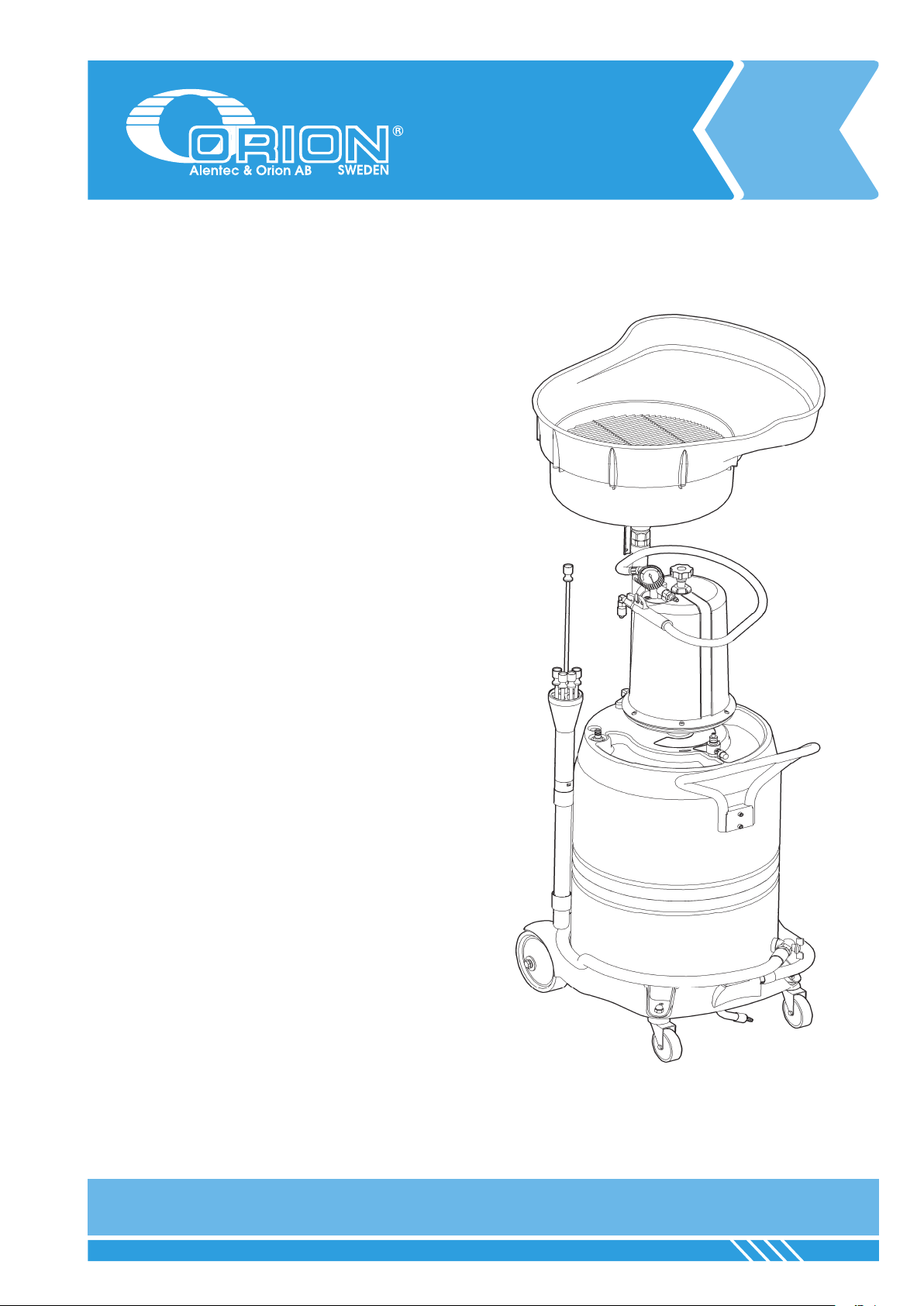
The design and manufacturing of the equipment WASTE OIL DRAINER,
29505, 29507, 29508, 39505, 39507, 39508, 39517 as well as the tests
carried out on the said model follow, by Alentec&Orion AB’s own will, the
recommendations stated in the part 1 of the UNE EN-286 Directive, «Simple
unred pressure vessels designed to contain air», and more specically
in the Class 3 vessels indication (Vessels with PS x V < 200 ) stated in
paragraph 4 in the said Directive.
The Alentec&Orion AB brand mobile combined suction drainer for
the collection of waste oil by gravity or depression, model WASTE OIL
DRAINER, 29505, 29507 AND 29508 are units which:
• ARE NOT submitted to the Directive of Pressurezed Devices
87/404/CEE and its amendments 90/488/CEE and 93/68/CEE, as
the internal working pressure, during the depressuring phase of the
metallic container of 100 litres, is of 0,5 bar or less.
• ARE NOT submitted to the Directive of Machine Security 89/392/
CEE and its amendments 93/44/CEE, 93/68/CEE and 98/37/CEE, as
there are no mobile elements in its operating system.
• DO RESPOND to the Directive of Security of Operating Equipment
89/655/CEE and its amendment 95/63/CEE.
ALWAYS follow the operating instructions indicated in the Manual Guide,
which is supplied with the product.
NEVER manipulate the security valve placed beside the charge valve.
NEVER exceed the 0.5 bar pressure when emptying the metallic container.
Remember to always empty the waste oil drainer to prevent ammable
uids are stored in spaces which are not re rated.
Konstruktion och tillverkning av SPILLOLJEBEHÅLLARE 29505, 29507,
29508, 39505, 39507, 39508, 39517 samt tester gjorda på nämnda modeller
har, genom vårt eget åtagande, utförts i enlighet med Del 1 i UNE-EN 286
Direktivet «Simple unred pressure vessels designed to contain air», och
mer specicerat i klass 3 Behållare där tryck (P) gånger volym (V) skall
understiga 200. (P (bar) x V (liter) < 200) och som anges i paragraf 4 i
nämnda direktiv
De av oss tillverkade modellerna för tömning och förvaring av spillolja är
produkter som:
• INTE omfattas av bestämmelserna i Directive of Pressurezed
Devices 87/404/CEE och sina tillägg 90/488/CEE och 93/68/
CEE angående internt tryck, eftersom det understiger 0,5 bar och
behållaren inte är större än 100 liter.
• INTE omfattas av bestämmelserna i Directive of Machine Security
89/392/CEE och sina tillägg 93/44/CEE, 93/68/CEE och 98/37/CEE,
därför att det inte nns några rörliga maskindelar i utrustningen.
• OMMFATTAS av Directive of Security of Operating Equipment
89/655/CEE och sitt tillägg 95/63/CEE.
Följ ALLTID de användarinstruktioner som anges i denna bruksanvining,
vilken medföljer produkten.
Manipulera ALDRIG säkerhetsventilen som sitter bredvid
trycktömningsventilen.
Överstig ALDRIG 0,5 bars tryck i behållaren vid trycktömning.
Tänk på att tömma spilloljebehållaren för att undvika att brandfarlig vätska
nns i utrymmen som ej är brandklassade.
Olle Berglund
Product Director
This manual suits for next models
3
Table of contents
Other Orion Industrial Equipment manuals
Popular Industrial Equipment manuals by other brands

Schrempp electronic
Schrempp electronic MG-3-T4-TRIO IOL M8 manual

ABB
ABB HT607332 Operation manual

SKF
SKF TMDS 6 Instructions for use

ABB
ABB HT604083 Operation manual

Dorner
Dorner MPB 2100 Series Installation, maintenance & parts manual

dunkermotoren
dunkermotoren AMETEK BG 75 dMove Translation of the original function and connection guide