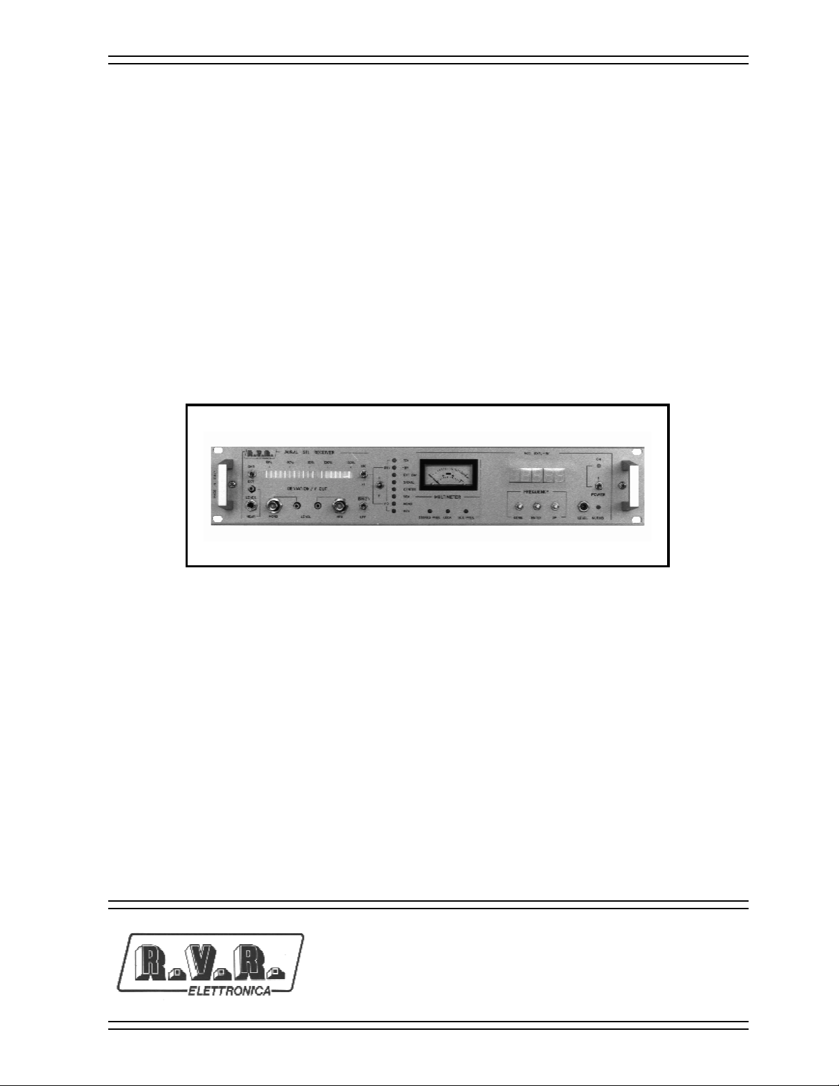
R.V.R. Elettronica RXRL-NV User manual
Other R.V.R. Elettronica Industrial Equipment manuals

R.V.R. Elettronica
R.V.R. Elettronica RXRL-NV/2 User manual

R.V.R. Elettronica
R.V.R. Elettronica VJ3000 User manual

R.V.R. Elettronica
R.V.R. Elettronica PTRL-NV/2/S3 User manual

R.V.R. Elettronica
R.V.R. Elettronica URPT/MIC User manual

R.V.R. Elettronica
R.V.R. Elettronica SDC2000 User manual

R.V.R. Elettronica
R.V.R. Elettronica TEX150-LCD/S User manual

R.V.R. Elettronica
R.V.R. Elettronica TJ5KPS User manual

R.V.R. Elettronica
R.V.R. Elettronica BLUES 30 User manual

R.V.R. Elettronica
R.V.R. Elettronica TELINK-SNMP2 User manual

R.V.R. Elettronica
R.V.R. Elettronica PJ5KPS User manual

R.V.R. Elettronica
R.V.R. Elettronica VJ1000HP User manual

R.V.R. Elettronica
R.V.R. Elettronica TLC300 User manual

R.V.R. Elettronica
R.V.R. Elettronica PTX-LCD User manual

R.V.R. Elettronica
R.V.R. Elettronica HC4 User manual

R.V.R. Elettronica
R.V.R. Elettronica PTX30 UHT/S3 User manual

R.V.R. Elettronica
R.V.R. Elettronica TRDS4001 User manual

R.V.R. Elettronica
R.V.R. Elettronica PTRL NV/3 User manual

R.V.R. Elettronica
R.V.R. Elettronica TELINK-SNMP1 User manual

R.V.R. Elettronica
R.V.R. Elettronica TEX150 User manual

R.V.R. Elettronica
R.V.R. Elettronica URP User manual