SPE CBSW1-S User manual

CBSW1-S
CBSW2-S
USER MANUAL
BETRIEBSHANDBUCH
MANUALE DI ISTRUZIONI
MODE D'EMPLOI
MANUAL DEL USUARIO
Before connecting the battery charger to the mains and to the battery, READ THE
FOLLOWING INSTRUCTIONS CAREFULLY.
Vor dem Anschließen des Batterieladegeräts an das Stromnetz und an die Batterie
UNBEDINGT AUFMERKSAM NACHSTEHENDE ANLEITUNGEN LESEN.
Prima di connettere il caricabatterie alla rete ed alla batteria, VI PREGHIAMO DI
LEGGERE ATTENTAMENTE LE SEGUENTI ISTRUZIONI.
Avant de connecter le chargeur de batterie au secteur et à la batterie, NOUS VOUS
PRIONS DE LIRE ATTENTIVEMENT LES INSTRUCTIONS SUIVANTES.
Antes de conectar el cargador a la red eléctrica y a la bater a, LEER
CUIDADOSAMENTE LAS SIGUIENTES INSTRUCCIONES.


Model
Modell
Modello
Modèle
Modelo
Vol age
Spannung
Tensione
Tension
Tensión
Curren
S rom
Corren e
Couran
Corrien e
Charging Curve
Ladekurve
Curva di Carica
Courbe de Charge
Curva de Carga
IUIa
ACD
IUIa
GEL
IUIa
AGM
IUUo
GEL
OTHER
ANDERES
ALTRO
AUTRE
OTROS
CBSW1-S 12V 4A
CBSW1-S 12V 8A
CBSW1-S 12V 10A
CBSW1-S 12V 12A
CBSW1-S 24V 4A
CBSW1-S 24V 8A
CBSW1-S 24V 10A
CBSW1-S 24V 12A
CBSW2-S 12V 15A
CBSW2-S 12V 20A
CBSW2-S 12V 25A
CBSW2-S 12V 30A
CBSW2-S 24V 15A
CBSW2-S 24V 20A
CBSW2-S 24V 25A
CBSW2-S 24V 30A
CBSW2-S 36V 15A
CBSW2-S 36V 20A
CBSW2-S 36V 25A
CBSW2-S 36V 28A
CBSW2-S 48V 15A
CBSW2-S 48V 20A
OTHER ANDERES ALTRO AUTRE OTROS
Model
Modell
Modello
Modèle
Modelo
Vol age
Spannung
Tensione
Tension
Tensión
Curren
S rom
Corren e
Couran
Corrien e
Charging Curve
Ladekurve
Curva di Carica
Courbe de Charge
Curva de Carga
IUIa
ACD
IUIa
GEL
IUIa
AGM
IUUo
GEL
OTHER
ANDERES
ALTRO
AUTRE
OTROS
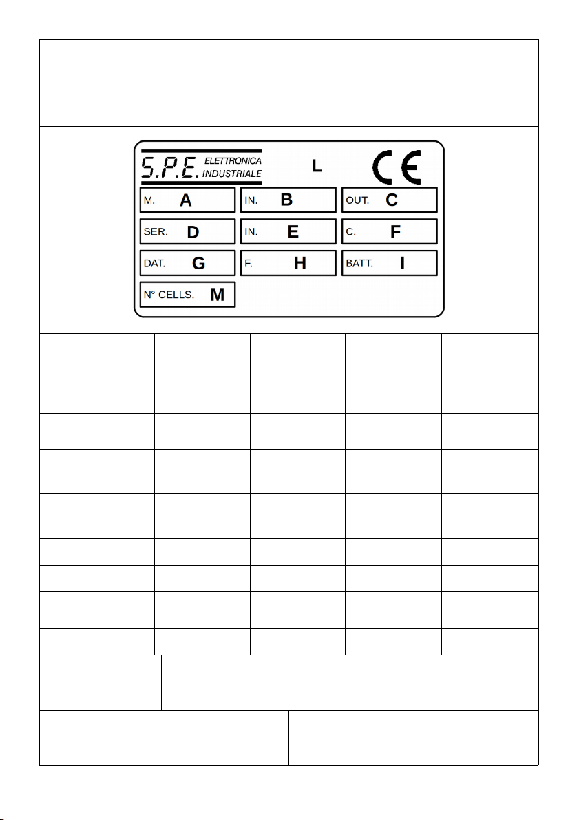
BATTERY CHARGER IDENTIFICATION LABEL
TYPENSCHILD DES BATTERIE-LADEGERÄTES
ETICHETTA IDENTIFICATIVA DEL CARICABATTERIA
ÉTIQUETTE D’IDENTIFICATION DU CHARGEUR DE BATTERIE
ETIQUETA DE IDENTIFICACIÓN DEL CARGADOR DE BATERĺA
A MODEL MODELL MODELLO MODÈLE MODELO
B INPUT VOLTAGE VERSORGUNGSSPAN
NUNG
TENSIONE DI
ALIMENTAZIONE
TENSION
D’ALIMENTATION
TENSIÓN DE
ALIMENTACIÓN
COUTPUT VOLTAGE
AND CURRENT
AUSGANGS-
SPANNUNG UND
STROM
TENSIONE E
CORRENTE DI
USCITA
TENSION ET
COURANT DE SORTIE
TENSIÓN Y
CORRIENTE DE
SALIDA
DBATTERY CHARGER
SERIAL NUMBER
SERIENNUMMER DES
BATTERIE-
LADEGERÄTES
NUMERO DI SERIE
DEL
CARICABATTERIA
NUMÉRO DE SÉRIE
DU CHARGEUR DE
BATTERIE
NÚMERO DE SERIE
DEL CARGADOR
E MAINS ABSORPTION NETZ-
STROMAUFNAHME
ASSORBIMENTO DI
RETE
ABSORPTION DE
RÉSEAU ABSORCIÓN DE RED
F CHARGING CURVE LADEKURVE CURVA DI CARICA COURBE DE CHARGE CURVA DE CARGA
GBATTERY CHARGER
MANUFACTURE DATE
HERSTELLUNGSDAT
UM DES BATTERIE-
LADEGERÄTES
DATA
FABBRICAZIONE DEL
CARICABATTERIA
DATE DE
FABRICATION DU
CHARGEUR DE
BATTERIE
FECHA DE
FABRICACIÓN DEL
CARGADOR
H MAINS FUSE VALUE WERT NETZ-
SICHERUNG
VALORE FUSIBILE DI
RETE
VALEUR FUSIBLE DE
RÉSEAU
VALOR FUSIBLE DE
RED
IBATTERY CAPACITY
RANGE
BEREICH
BATTERIELEISTUNG
GAMMA CAPACITA'
BATTERIE
GAMME CAPACITÉ
DES BATTERIES
GAMA DE CAPACIDAD
BATERIAS
L
PRODUCT
CERTIFICATION
STAMPS
KENNZEICHNUNG
PRODUKTZERTIFIZIE
RUNG
MARCHI
CERTIFICAZIONE DI
PRODOTTO
MARQUES DE
CERTIFICATION DE
PRODUIT
MARCAS DE
CERTIFICACIÓN DEL
PRODUCTO
M NUMBER OF CELLS ANZAHL VON ZELLEN NUMERO DI CELLE NOMBRE DE
CELLULES
NUMERO DE
CELULAS
Storage temperature: from -20°C to +50°C;
Lagertemperatur: von -20°C bis +50°C;
Temperatura di immagazzinamento: da -20°C a +50°C;
Température de stockage: de -20°C à +50°C;
Temperatura de almacenamiento: de -20°C a +50°C;
Relative humidity: 0 – 80% up to 50°C;
Relative Feuchtigkeit: 0 – 80% bis 50°C;
Umidità relativa: 0 – 80% fino a 50°C;
Humidité relative: 0 – 80% jusqu’à 50°C;
Humedad relativa: 0 – 80% hasta 50°C;
Operating temperature: from 0°C to 40°C;
Betriebstemperatur: von 0°C bis 40°C;
Temperatura operativa: da 0°C a 40°C;
Température d’exploitation: de 0°C à 40°C;
Temperatura operativa: de 0°C a 40°C;


MOD. CBSW-S
OFF
ON
1
4 5 6
SMART ELECTRONIC BATTERY CHARGER
HIGH FREQUENCY SYSTEM
2
A = Amps
U = Volts
= ours
C = A
E = KW
3
S

Operating Manual
OPERATING MANUAL
GENERAL INFORMATION AND WARNING
•Electronic automatic battery charger with microprocessor suitable for any battery type;
•Fully automatic charging cycle with electronic setting; protected against overload, short – circuit at clamps and
reversed polarity;
•Never disconnect the battery while charging: this could cause sparks;
•Never use the equipment in the rain, in areas used for washing or in damp areas;
•Before starting to charge, make sure the voltage of the equipment suits the voltage of the battery, that the
charging current suits the capacity of the battery and that the selected charging curve (for lead – acid batteries
or airtight gel batteries) is correct for the type of battery to be charged. In addition, make sure the rated input
voltage of the charger suits the available supply voltage and the system is equipped with grounding;
•If necessary, replace the fuse with another of the same type and the value as indicated on the rating plate;
•Use the battery chargers only in well ventilated areas;
•Pay attention to any remarks of the battery manufacturer;
For lead – acid ba eries wi h liquid elec roly e:
•Control the water level after each charging process;
•Refill with distilled water only;
•Caution! The gases generated during charging are explosive. Do not smoke in the vicinity of the batteries. When
working with cables and electrical equipment, avoid open flames and sparks.
•Attention: Use protective glasses and gloves during battery maintenance. Battery acid cause injuries. In case of
contact with battery acid, wash the affected parts with a lot of fresh water and consult a doctor if necessary.
CONTROLS (see figure behind he cover)
1. Main switch (1): when in the “OFF” position, the device is disconnected from the supply mains by two poles;
when in the “ON” position, the device is connected;
2. Three digit display + symbol (2), to view A = the charging current, U = the battery voltage, h = the charging time,
C = the charging ampere – hours [Ah], E = the energy used [KWh];
3. Button for the selection of the display mode (3): A, U, h, C, E. After about 10 seconds the display returns to the
visualization of the charging current;
4. Red control indicator (4): when it is on, the charging cycle has started;
5. Yellow control indicator (5): when it is on, the final phase of the charging cycle has started;
6. Green control indicator (6): when it is on, the charging cycle has finished.
OPERATION
•Put the main switch (1) in the “OFF” position and connect the plug of the feeding cable to a supply plug;
•Connect the battery, checking the polarity;
•Bring the switch (1) to “ON”, thus starting the automatic charging cycle. Now, the battery charger's display will
show a sequence of details on the charger's internal programming: after the name “SPE”, it will show the
software release installed in the equipment, then, in sequence, the following parameters: battery voltage,
charging current, charging curve number and, finally, the words “GEL” or “Acd” depending on the set up
charging curve being suitable for airtight gel batteries ore lead – acid batteries. Make sure he ype of ba eries
o be charged (gel ore lead . Acid ba eries) ma ches he displayed de ails (“GEL” or “Acd”,
respec ively). If i doesn' , con ac our dealer. Now, a test is run on the battery voltage to decide if the
charging process should be started or not. If the battery is not connected to the battery charger, the display will
shown the word “ba ”. The word will stay on, even if the test is failed (for instance, reversed polarities or
incorrect battery connection). If the test is passed, the display the display will show the battery for approximately
5 seconds and the battery will begin to be charged. The charging cycle progress will be shown by red (4), yellow
(5) and green (6) LED indicators.
•At the end of charge, when the green indicator is on, put the main switch (1) in the “OFF” position and
disconnect the battery.
PROBLEMS SOLUTIONS AND CHECKS
The battery charge does not switch on Check that the plug is connected to the supply mains
and that the fuse is efficient
The charging cycle does not start and the message
“bat” is displayed
Check the connection to the battery and the polarity
The yellow indicator (5) will not light up even 15 hours
from the starting of the charging cycle, and the display
Check the battery for possible faulty components
D00613-00 7

Operating Manual
shows “E03”
The message “E01” is displayed This means that the maximum voltage admissible by the
battery has been exceeded. The charging is interrupted
If the battery charger is provided with a safety
thermostat and the message “E02” is displayed
This means that the maximum temperature has been
exceeded. The charging is interrupted.
The message “E03” is displayed This means that the maximum time for the charging
phase has been exceeded. The charging is interrupted.
The message “SCt” is displayed This means that the total safety timer has interrupted the
charging
The message “Srt” is displayed This signals a possible internal short circuit
8 D00613-00

CE DECLARATION OF CONFORMITY
According o: UNI CEI EN ISO/IEC 17050-1:2010
We
S.P.E. ELETTRONICA INDUSTRIALE DI POLETTI SERGIO
Via di Mezzo Ponen e, 383 – 40014 Crevalcore (Bologna) ITALY
Declare under our sole responsibility that the product:
ELECTRONIC AUTOMATIC BATTERY CHARGER MODEL:
CBSW1-S 12V 4A, CBSW1-S 12V 8A, CBSW1-S 12V 10A, CBSW1-S 12V 12A
CBSW1-S 24V 4A, CBSW1-S 24V 8A, CBSW1-S 24V 10A, CBSW1-S 24V 12A
CBSW2-S 12V 15A, CBSW2-S 12V 20A, CBSW2-S 12V 25A, CBSW2-S 12V 30A
CBSW2-S 24V 15A, CBSW2-S 24V 20A, CBSW2-S 24V 25A, CBSW2-S 24V 30A
CBSW2-S 36V 15A, CBSW2-S 36V 20A, CBSW2-S 36V 25A, CBSW2-S 36V 28A
CBSW2-S 48V 15A, CBSW2-S 48V 20A
to which this declaration applies, complies with the provisions of the Directives of the Council of the European Union
on the approximation of the laws of the members states:
Relating electromagnetic compatibility (EMC) directive 2014/30/EC of the European Parliament and of the Council of
26 February 2014 on the approximation of the laws of member states relating to electromagnetic compatibility and
repealing directive 89/336/EEC, conformity is proven by compliance with the following standards:
✔EN 55014-1:2008+A1:2010+A:2012 (Emission)
✔EN 55014-2:1998+A1:2002+A2:2007+A3:2009 (Immunity – Category II)
✔EN 61000-3-2:2015 (Harmonic Current Emission)
✔EN 61000-3-3:2014+A1:2014 (Voltage Fluctuation and Flicker)
Relating extra low voltage (LVD) directive 2014/35/EC of the European Parliament and of the Council of 26 February
2014 on the harmonisation of the laws of member states relating to electrical equipment designed for use within
certain voltage limits, conformity is proven by compliance with the following standards:
✔EN 60335-1:2013+A11:2015
"Safety of household and similar electrical appliance - art 1: General requirements".
✔EN 60335-2-29:2006+A2:2011
"Safety of household and similar electrical appliance - art 2: articular requirements for battery chargers".
✔EN 62233:2009
"Measurement methods for electromagnetic fields of household appliances and similar apparatus with regard to
human exposure".
Crevalcore 11-12-2015 Sergio Pole i
Presiden

Benutzer - handbuch
BENUTZER - HANDBUCH
ALLGEMEINE INFORMATIONEN UND WARNUNGEN
•Für jeden Batterietyp geeignetes elektronisches automatisches Ladegerät mit Mikroprozessor;
•Volkommen automatischer, elektronisck gesteuerter Ladevorgang. Schutz gegen Überlast, Kurzschluß an den
Klemmen and Umpolung;
•Die Batterie niemals während des Ladevorganges abklemmen, da Funken enststehen könnten;
•Das Gerät niemals bei Regen, in Waschräumen und bei hoher Luftfeuchtigkeit im allgemeinen verwenden;
•Vor Beginn des Ladevorgangs überprüfen, ob das Gerät der Batteriespannung entspricht, ob der Ladestrom
entsprechend der Batteriekapazität eingestellt ist und ob die gewählte Ladekurve (für Bleisäure – und
hermetisches Gelbatterien) des zu ladenden Batterietyps korrkt ist. Weiterhin kontrollieren, ob die
Eingangsspannung des Ladegerätes, dessen Daten auf dem Firmenschild angegeben sind, der verfügbaren
Ladespannung entspricht und ob die Anlage geerdet ist.
•Sofern enforderlich, Die Schmelszsicherung durch eine Sicherung gleichen Typs und mit den gleichen
Stromwerten ersetzen (siehe Typenschild);
•Das Ladegerät nur an einem gut belüfteten Ort verwenden;
•Die Hinweise des Herstellers der Batterie beachten;
Für Bleisäureba erien mi flüßigem Elek roly :
•Nach jedem Ladezyklus den Wasserstand Kontrollieren;
•Nur mit destilliertem Wasser nachfüllen;
•Achtung! Die während des Ladevorganges abgegebenen Gase sind explosiv. In der unmittelbaren N ähe der
Batterien nicht rauchen. Bei Arbeiten mit Kabeln und elektrischen Geräten sind offenes Feuer and Funken zu
meiden;
•Achtung: Währendder Wartungsarbeiten Schutzbrille and Handschuhe tragen. Die in der Batterie enthaltene
Säure ist ätzend. Bei Kontakt mit der Säure aus der Batterie die betroffene Stelle mit Leitungswasser spülen und
umgehend einen Artz aufsuchen.
STEUERUNGEN (siehe Rücksei e des Deckbla es)
1. Hauptschalter (1): Wenn er “OFF“ (“AUS“) ist, ist das Gerät vom Netz bei zwei Polen ausgeschaltet; wenn er
“ON“ (“EIN“) ist, ist das Gerät angeschlossen;
2. 3 – stellige Anzeige + Symbol (2), zur Anzeige von A = Ladestrom, U = Batteriespannung, h = Ladezeit, C =
Ladeameperestunden [Ah], E = gebrauchte Energie [Kwh];
3. Druckknopf zur Auswahl der Anzeigemodalität (3): A, U, h, C, E. Nach zirka 10 Sekunden geht die Anzeige
immer zum Ladestrom zurück;
4. Roter Kontrollanzeiger leuchtet (4): der Ladezyklus hat begonnen;
5. Gelber Kontrollanzeiger leuchtet (5): die Endphase de Ladezyklus läuft;
6. Grüner Kontrollanzeiger leuchtet (6): der Ladezyklus ist beendet.
BETRIEB
•Den Hauptschalter (1) auf “OFF“ stellen und den Stecker des Netzkabels in eine Steckdose stecken;
•Die Batterie unter Beachtung der Polarität am Ladestecker anschliessen;
•Den Schalter (1) in Position “ON“ bringen und den automatischen Ladezyklus beginnen. An diesem Punkt
werden auf dem Display des Batterie – Ladegerätes in Sequenz verschiedene Informationen über das interne
Programm des Ladegerätes angezeigt: Nach der Anzeige “SPE“ wird die im Gerät installierte Software –
Version dargestellt und danach die folgenden Parameter: Batteriespannung, Ladestrom, Zahl der Ladekurve und
zuletzt die Mitteilung “GEL“ oder “Acd“ jenachdem ob die eingegebene Ladekurve hermetischen GEL –
Batterien oder Bleisäurebatterien entspricht. Kon rollieren, ob die zu ladende Ba erie (GEL – oder
Bleisäureba erien) mi den auf dem Display darges ell en Da en (en weder “GEL“ oder “Acd“
übereins imm . Is dies nich der Fall den Wiederverkäufer kon ak ieren. An diesem Punkt wird ein Test
über die Batteriespannung ausgeführt, um zu entscheiden ob der Ladeprozeß begonnen werden kann oder
nicht. Ist die Batterie nicht mit dem Ladegerät verbunden erscheint auf dem Display die Anzeige (ba ). Diese
Anzeige bleibt auch im Falle eines negativen Testergebnisses erhalten (z.B. ausgetauschte Polarität oder
falsche Verbindung mit der Batterie). Wenn der Test ein positives Ergebnis gebracht hat, wird auf dem Display
etwa fünf Sekunden lang der Wert der Batteriespannung angezeigt und der Ladevorgang begonnen. Das
Fortschreiten des Ladezyklus wird über drei LED – Leuchtanzeigen rot (4), gelb (5) und grün (6) angezeigt.
•Am Ende der Ladung, bei eingeschaltetem grünem Anzeiger, den Hauptschalter (1) auf “OFF“ stellen und die
Batterie ausschliessen.
PROBLEME LÖSUNGEN UND ÜBERPRÜFUNGEN
Das Ladegerät schaltet nicht ein Überprüfen, ob das Netzkabel in der Steckdose gesteckt
ist, und ob die Sicherung intakt ist
10 D00613-00

Benutzer - handbuch
Der Ladezyklus startet nicht und die Schrift “ba “ wird
angezeigt
Der Auschluß zur Batterie und die richtige Polarität
überprüfen
Die gelbe Anzeige (5) leuchtet auch nach 15 Stunden
nach Beginn des Ladezyklus nicht auf und auf dem
Display erscheint die Anzeige E03
Die Batterie kontrollieren: Sie könnte defekte Bestndteile
haben
Die Schrift E01 wird angezeigt Das bedeutet, daß die maximale Spannung, die von der
Batterie angenommen werden kann, überschritten
wurde. Die Ladung wird unterbrochen
Bei mit Schutz – Thermoschalter vesehenen
Ladegeräten wird die Schrift E02 angezeigt
Das bedeutet, daß die maximale Temperatur,
überschritten wurde. Die Ladung wird unterbrochen
Die Schrift E03 wird angezeigt Das bedeutet, daß die maximale Dauer für die Ladezeit
überschritten wurde. Die Ladung wird unterbrochen
Die Schrift SCt wird angezeigt Das bedeutet, daß der totale Schutztimer die Ladung
unterbrochen hat
Die Schrift Srt wird angezeigt Das signalisiert einen möglichen internen Kurzschluß
D00613-00 11

EG-KONFORMITÄTSERKLÄRUNG
im sinne von UNI CEI EN ISO/IEC 17050-1:2010
Die unterzeichnende firma:
S.P.E. ELETTRONICA INDUSTRIALE DI POLETTI SERGIO
Via di Mezzo Ponen e, 383 – 40014 Crevalcore (Bologna) ITALIA
erklärt eigenverantwortlich, dass das Produkt:
AUTOMATISCHES ELEKTRONISCHES BATTERIELADEGERÄT MODELL:
CBSW1-S 12V 4A, CBSW1-S 12V 8A, CBSW1-S 12V 10A, CBSW1-S 12V 12A
CBSW1-S 24V 4A, CBSW1-S 24V 8A, CBSW1-S 24V 10A, CBSW1-S 24V 12A
CBSW2-S 12V 15A, CBSW2-S 12V 20A, CBSW2-S 12V 25A, CBSW2-S 12V 30A
CBSW2-S 24V 15A, CBSW2-S 24V 20A, CBSW2-S 24V 25A, CBSW2-S 24V 30A
CBSW2-S 36V 15A, CBSW2-S 36V 20A, CBSW2-S 36V 25A, CBSW2-S 36V 28A
CBSW2-S 48V 15A, CBSW2-S 48V 20A
auf das sich vorliegende Erklärung bezieht, den Richtlinien des Rats der Europäischen Union betreffend die
Annäherung der Bestimmungen der Mitgliedsstaaten entspricht:
Im Hinblick auf die Richtlinie zur elektromagnetischen Verträglichkeit (EMV) 2014/30/EG des Europäischen
Parlaments und Rats vom 26. Februar 2014 betreffend die Annäherung der Gesetzgebungen der Mitgliedsstaaten
über die elektromagnetische Verträglichkeit und unter Aufhebung der Richtlinie 89/336/EWG ist die Konformität
nachgewiesen, wenn nachstehende Normen beachtet sind:
✔EN 55014-1:2008+A1:2010+A2:2012 (Emissionen)
✔EN 55014-2:1998+A1:2002+A2:2007+A3:2009 (Immunität – Kategorie II)
✔EN 61000-3-2:2015 (Oberschwingungsströme )
✔EN 61000-3-3:2014+A:2014 (Spannungsschwankungen und Flicker)
Im Hinblick auf die Niederspannungsrichtlinie 2014/35/EG des Europäischen Parlaments und Rats vom 26. Februar
2014 betreffend die Annäherung der Gesetzgebungen der Mitgliedsstaaten für Elektrogeräte innerhalb bestimmter
Spannungsgrenzen, ist die Konformität nachgewiesen, wenn nachstehende Normen beachtet werden.
✔EN 60335-1:2013+A11:2015
"Sicherheit elektrischer geräte für den hausgebrauch und ähnliche zwecke - Teil 1: Allgemeine anforderungen".
✔EN 60335-2-29:2006+A2:2011
" Sicherheit elektrischer geräte für den hausgebrauch und ähnliche zwecke - Teil 2: Besondere anforderungen
für batterieladegeräte".
✔EN 62233:2009
"Verfahren zur messung der elektromagnetischen felder von haushaltsgeräten und ähnlichen elektrogeräten im
hinblick auf die sicherheit von personen".
Crevalcore, den 11.12.2015 Sergio Pole i
Präsiden

Manuale Operativo
MANUALE OPERATIVO
INFORMAZIONI GENERALI ED AVVERTENZE
•Carica batterie elettronico automatico a microprocessore adatto per tutti i tipi di batterie;
•Ciclo di carica completamente automatico con regolazione elettronica; protezione in caso di sovraccarico,
cortocircuito ai morsetti e inversione di polarità;
•Non disconnettere mai la batteria durante la carica: questa operazione potrebbe provocare scintille;
•Non usare mai l'apparecchio in presenza di pioggia, in locali adibiti a lavaggio o in ambienti umidi;
•Controllare, prima di iniziare la carica, che l'apparecchio soddisfi la tensione della batteria, che la corrente di
carica sia appropriata alla capacità della batteria e che la dinamica di ricarica selezionata (per batterie al Pb –
Acido o per batterie ermetiche al Gel) sia corretta per il tipo di batteria da caricare. Inoltre verificare che la
tensione di ingresso del caricatore indicata sui dati di targa soddisfi la tensione di alimentazione disponibile e
che l'impianto sia provvisto di messa a terra;
•In caso di necessità sostituire il fusibile con uno di uguale tipo e valore come indicato dai dati di targa;
•Usare il carica batteria solo in area ben ventilata;
•Fare attenzione ad ogni indicazione fornita dal costruttore di batterie;
Per ba erie al piombo acido con ele roli o liquido:
•Controllare il livello dell'acqua dopo ogni ciclo di carica;
•Riempire di nuovo solo con acqua distillata;
•Attenzione! I gas emanati durante la carica sono esplosivi. Non fumare nelle immediate vicinanze delle batterie.
Quando si lavora con cavi e apparecchi elettrici, evitare fiamme libere e scintille;
•Attenzione: usare occhiali protettivi e guanti durante la manutenzione. L'acido della batteria provoca danni. In
caso di contatto con l'acido della batteria, lavare la parte interessata con acqua fresca e consultare un medico
se necessario.
ELEMENTI DI COMANDO (vedi la figura nel re ro della coper ina)
1. Interruttore generale (1): quando è in posizione “OFF” l'apparecchio è staccato dalla rete con 2 poli; quando è in
posizione “ON”, l'apparecchio è inserito;
2. Display a 3 digit + simbolo (2), per visualizzare A = corrente di carica, U = Tensione di batteria, h = tempo di
carica, C = amperora di carica [Ah], E = energia utilizzata [KWh];
3. Tasto di Selezione della modalità di visualizzazione del display (3): A, U, h, C, E. Dopo circa 10 secondi il display
torna sempre a visualizzare la corrente di carica;
4. Segnalatore rosso di controllo (4): quando è acceso significa che è iniziato il ciclo di carica;
5. Segnalatore giallo di controllo (5): quando è acceso significa che è in atto la fase finale del ciclo di carica;
6. Segnalatore verde di controllo (6): quando è acceso significa che è terminato il ciclo di carica;
FUNZIONAMENTO
•Disporre l'interruttore generale (1) in posizione “OFF” ed inserire la spina del cavo di alimentazione in una presa
di corrente;
•Collegare la batteria rispettando la polarità;
•Disporre l'interruttore (1) in posizione “ON” dando inizio al ciclo automatico di carica. A questo punto, sul display
del carica batterie vengono visualizzate in sequenza diverse informazioni relative alla programmazione interna
del caricatore: dopo la scritta “SPE” viene presentata la versione del software installato nell'apparecchio, poi, in
successione, vengono visualizzati i seguenti parametri: tensione di batteria, corrente di carica, numero della
curva di carica e, infine, la scritta “GEL” oppure “Acd” a seconda che la curva di carica impostata sia adatta
per batterie ermetiche al Gel o per batterie al Pb – Acido. Verificare che il ipo di ba erie da caricare (al Gel o
al Pb – Acido) corrisponda con l'indicazione da a dal display (rispe ivamen e “GEL o “Acd”). In caso
con rario con a are il vos ro rivendi ore. A questo punto viene eseguito un test sulla tensione di batteria per
decidere se iniziare o meno il processo di carica. Se la batteria non è connessa al carica batteria sul display
appare la scritta “ba ”. La scritta permane anche in caso di esito negativo del test (ad esempio, polarità invertita
o errata connessione con la batteria). Se il test ha dato esito positivo, viene visualizzato a display il valore della
tensione di batteria per un tempo di circa 5 secondi ed inizia la carica della batteria. L'avanzamento del ciclo di
carica è segnalato tramite tre segnalatori luminosi a led: rosso (4), giallo (5), verde (6).
•Alla fine della carica, con segnalatore verde acceso (6), disporre l'interruttore generale (1) in posizione “OFF” e
sconnettere la batteria.
PROBLEMI SOLUZIONI E VERIFICHE
Il carica batteria non si accende Controllare la presenza della spina nella presa di rete e
l'efficienza dei fusibili
Non inizia il ciclo di carica e il display presenta la scritta Controllare la connessione con la batteria ed il rispetto
D00613-00 13

Manuale Operativo
“ba ” della polarità
Non si accende il segnalatore giallo (5) anche dopo 15
ore dall'inizio del ciclo di carica ed il display presenta la
scritta E03
Controllare la batteria: potrebbe avere elementi difettosi
Il display presenta la scritta E01 Significa che è stata superata la massima tensione
ammessa dalla batteria. La carica viene interrotta
Se il carica batterie è provvisto di termostato di
sicurezza e il display presenta la scritta E02
Significa che è stata superata la massima temperatura.
La carica viene interrotta
Il display presenta la scritta E03 Significa che è stata superata la durata massima
prevista per la fase di carica. La carica viene interrotta
Il display presenta la scritta SCt Significa che è intervenuto il timer di sicurezza totale ad
interrompere la carica
Il display presenta la scritta Srt Segnala un possibile cortocircuito interno
14 D00613-00

DICHIARAZIONE DI CONFORMITA' CE
Ai sensi dei UNI CEI EN ISO/IEC 17050-1:2010
La sottoscritta
S.P.E. ELETTRONICA INDUSTRIALE DI POLETTI SERGIO
Via di Mezzo Ponen e, 383 – 40014 Crevalcore (Bologna) ITALIA
Dichiara sotto la propria esclusiva responsabilità che il prodotto:
CARICABATTERIA ELETTRONICO AUTOMATICO MODELLO:
CBSW1-S 12V 4A, CBSW1-S 12V 8A, CBSW1-S 12V 10A, CBSW1-S 12V 12A
CBSW1-S 24V 4A, CBSW1-S 24V 8A, CBSW1-S 24V 10A, CBSW1-S 24V 12A
CBSW2-S 12V 15A, CBSW2-S 12V 20A, CBSW2-S 12V 25A, CBSW2-S 12V 30A
CBSW2-S 24V 15A, CBSW2-S 24V 20A, CBSW2-S 24V 25A, CBSW2-S 24V 30A
CBSW2-S 36V 15A, CBSW2-S 36V 20A, CBSW2-S 36V 25A, CBSW2-S 36V 28A
CBSW2-S 48V 15A, CBSW2-S 48V 20A
cui si riferisce la presente dichiarazione, è conforme alle disposizioni di cui alle Direttive del Consiglio dell'Unione
Europea concernenti il ravvicinamento delle normative degli stati membri:
Con riguardo alla Direttiva sulla Compatibilità Elettromagnetica (EMC) 2014/30/CE del Parlamento e del Consiglio
Europei datata 26 Febbraio 2014 sul ravvicinamento delle legislazioni degli Stati Membri sulla compatibilità
elettromagnetica e in abrogazione della Direttiva 89/336/CEE, la conformità è provata qualora i seguenti standard
siano rispettati:
✔EN 55014-1:2008+A1:2010+A:2012 (Emissioni)
✔EN 55014-2:1998+A1:2002+A2:2007+A3:2009 (Immunità – Categoria II)
✔EN 61000-3-2:2015 (Emissioni di Corrente Armonica)
✔EN 61000-3-3:2014+A1:2014 (Fluttuazioni di Tensione e Flicker)
Con riguardo alla Direttiva Bassa Tensione (LVD) 2014/35/CE del Parlamento e del Consiglio Europei datata 26
Febbraio 2014 sul ravvicinamento delle legislazioni degli Stati Membri sugli apparati elettrici progettati per essere
utilizzati entro determinati limiti di tensione, la conformità è provata qualora i seguenti standard siano rispettati:
✔EN 60335-1:2013+A11:2015
"Sicurezza degli apparecchi elettrici d'uso domestico e similare - arte 1: Norme Generali".
✔EN 60335-2-29:2006+A2:2011
"Sicurezza degli apparecchi elettrici d'uso domestico e similare - arte 2: Norme particolari per caricabatterie".
✔EN 62233:2009
"Metodi di misura per campi elettromagnetici degli apparecchi elettrici di uso domestico e similari con riferimento
all'esposizione umana".
Crevalcore 11-12-2015 Sergio Pole i
Presiden e

Manuel d'Usage
MANUEL D'USAGE
INFORMATIONS GENERALES ET AVERTISSEMENTS
•Chargeur de batteries électronique automatique à microprocesseur indiqué pour tous les types de batteries;
•Cycle de charge entièrement automatique avec réglage électronique; protections en cas de surcharge, court-
circuit aux bornes ou inversion de polarité;
•Ne jamais débrancher la batterie durant la charge: ceci pourrait provoquer des étincelles;
•Ne jamais utiliser l'appareil sous la pluie, dans des locaux de lavage ou des pièces humides;
•Avant d'amorcer le processus de chargement vérifier que l'équipement soit prévu pour satisfaire la tension de la
batterie, que le courant de chargement soit indiqué par rapport à la capacité de la batterie et que la courbe de
chargement sélectionnée (pour des batteries au Plomb – Acide ou pour des batteries étanches au Gel) soit
correcte par rapport au type de batterie à charger. Vérifier en outre que la tension d'entrée du chargeur de
batteries indiquée sur la plaquette de celui – ci soit adéquate pour satisfaire la tension d'alimentation disponible
et que l'équipement soit pourvu de mise à la terre;
•En case de nécessité, remplacer le fusible par un fusible de type et de valeur identiques, comme indiqué sur la
plaquette;
•Utiliser le chargeur de batteries uniquement dans des zones bien ventilées;
•Faire attention aux indications fournies par le fabricant de la batterie;
Pour ba eries au plomb acide avec élec roly e liquide
•Contrôler le niveau d'eau après chaque cycle de charge;
•Faire la mise a niveau uniquement avec de l'eau distillée;
•Attention! Les gaz dégagés durant la charge sont explosifs. Ne pas fumer à proximité des batteries. Eviter les
flammes libres et les étincelles en cas de manipulation avec des câbles ou des appareils électriques;
•Attention: utiliser des lunettes de protection ainsi que des gants durant la manipulation. L'acide de la batterie
provoque des dommages. En cas de contact avec l'acide de la batterie, laver la partie concernée avec de l'eau
fraîche et consulter un médecin en cas de nécessité.
ELEMENTS DE COMMANDE (voir la figure sur le verso de la couver ure)
1. Interrupteur général: (1) quand il est prévu sur «OFF» l'appareil est déconnecté du réseau avec 2 pôles; quand il
est prévu sur «ON», l'appareil est branché;
2. Visuel à 3 chiffres + symbole (2), pour afficher A = courant de charge, U = tension de batterie, h = temps de
charge, C = ampère heure de charge [Ah], E = énergie utilisée [KWh];
3. Touche de Sélection de la modalité d'affichage du visuel (3): A, U, h, C, E. Après environ 10 secondes le visuel
affiche toujours à nouveau le courant de charge;
4. Avertisseur rouge de contrôle (4): lorsqu'il est allumé, il signale que le cycle de charge a commencé;
5. Avertisseur jaune de contrôle (5): lorsqu'il est allumé, il signale que la phase finale du cycle de charge est en
cours;
6. Avertisseur vert de contrôle (6): lorsqu'il est allumé, il signale que le cycle de charge est terminé;
FONCTIONNEMENT
•Disposer l'interrupteur général (1) sur «OFF» et enfoncer la fiche du câble d'alimentation dans une prise de
courant;
•Connecteur la batterie en respectant la polarité;
•Placer l'interrupteur (1) dans la position «ON» pour faire démarrer le cycle automatique de chargement. A ce
moment – là, l'afficheur du chargeur de batteries montrera une séquence de renseignements concernant la
programmation interne du chargeur de batteries: après l'affichage du sigle «SPE» on pourra lire la version du
logiciel installé dans l'équipement; ensuite les paramètres suivants seront affichés dans l'ordre indiqué ci –
dessous: tension de la batterie, courant de chargement, numéro de la courbe de chargement et, enfin, le sigle
«GEL» ou «Acd» selon que la courbe de chargement établie soit indiquée pour des batteries étanches au Gel
ou pour des batteries au Plomb – Acide. Vérifier que le ype de ba eries à chargeur (au Gel ou au Plomb .
Acide) corresponde à l'indica ion mon rée sur l'afficheur (respec ivemen «GEL» ou «Acd»). Au cas
con raire, con ac er vo re revendeur. A ce point – là un test de la tension de la batterie est effectué pour
décider s'il faut amorcer le processus de chargement. Si la batterie n'est pas connectée au chargeur de
batteries, l'afficheur montrera le code «ba ». Ce code reste aussi affiché si le résultat du test est négatif (par
exemple, si la polarité est inversée ou la batterie est connectée de façon incorrecte). Si le résultat du test est
positif, l'afficheur montre la valeur de la tension de la batterie pendant 5 secondes environ et le processus de
chargement de la batterie est amorcé. La progression du cycle de chargement est signalé par trois voyants à
led: rouge (4), jaune (5), vert (6);
•A fin de la charge, avec l'avertisseur vert allumé, mettre l'interrupteur général (1) sur «OFF» et déconnecter la
batterie.
16 D00613-00

Manuel d'Usage
PROBLEMES SOLUTIONS ET VERIFICATIONS
Le chargeur de batterie ne se met pas en marche Contrôler si la fiche est bien enfoncée dans la prise de
courant ainsi que l'efficacité du fusible
Le cycle de charge ne démarre pas et sur le visuel
s'affiche le message «ba »
Contrôler la connexion à la batterie et si la polarité et
bien conforme
Le led jaune (5) ne s'allume pas, même 15 heures après
le démarrage du cycle de chargement, et le code E03
apparaît sur l'afficheur
Contrôler la batterie: il pourrait y avoir des éléments
défectueux
Le visuel affiche le message E01 Indique que la tension maximale autorisée par la batterie
a été dépassée. La charge est interrompue
Si le chargeur de batteries est doté d'un thermostat de
sécurité et le visuel affiche le message E02
Indique que la température maximale a été dépassée.
La charge est interrompue
Le visuel affiche le message E03 Indique que la durée maximale prévue pour la phase de
charge a été dépassée. La charge est interrompue
Le visuel affiche le message SCt Indique que le compteur temps de sécurité totale s'est
déclenché pour interrompre la charge
Le visuel affiche le message Srt Indique un court – circuit interne possible
D00613-00 17

DÉCLARATION DE CONFORMITÉ CE
D'après les normes UNI CEI EN ISO/IEC 17050-1:2010
La soussignée
S.P.E. ELETTRONICA INDUSTRIALE DI POLETTI SERGIO
Via di Mezzo Ponen e, 383 – 40014 Crevalcore (Bologne) ITALIE
Déclare sous sa propre et exclusive responsabilité que le produit:
CHARGEUR DE BATTERIE ÉLECTRONIQUE AUTOMATIQUE MODÈLE:
CBSW1-S 12V 4A, CBSW1-S 12V 8A, CBSW1-S 12V 10A, CBSW1-S 12V 12A
CBSW1-S 24V 4A, CBSW1-S 24V 8A, CBSW1-S 24V 10A, CBSW1-S 24V 12A
CBSW2-S 12V 15A, CBSW2-S 12V 20A, CBSW2-S 12V 25A, CBSW2-S 12V 30A
CBSW2-S 24V 15A, CBSW2-S 24V 20A, CBSW2-S 24V 25A, CBSW2-S 24V 30A
CBSW2-S 36V 15A, CBSW2-S 36V 20A, CBSW2-S 36V 25A, CBSW2-S 36V 28A
CBSW2-S 48V 15A, CBSW2-S 48V 20A
auquel cette déclaration se rapporte, est conforme aux dispositions des Directives du Conseil de l'Union Européenne
concernant le rapprochement des législations des États membres:
En matière de compatibilité électromagnétique (EMC), Directive 2014/30/CE du Parlement et du Conseil Européens
du 26 Février 2014 concernant le rapprochement des législations des États membres en matière de compatibilité
électromagnétique abrogeant la directive 89/336/CEE, la conformité est démontrée par le respect des normes
suivantes:
✔EN 55014-1:2008+A1:2010+A:2012 (Émissions)
✔EN 55014-2:1998+A1:2002+A2:2007+A3:2009 (Immunité – Catégorie II)
✔EN 61000-3-2:2015 (Émissions de Courant Harmonique)
✔EN 61000-3-3:2014+A1:2014 (Fluctuations de Tension et Flicker)
En matière de Basse Tension, Directive (LVD) 2014/35/CE du Parlement et du Conseil Européens du 26 Février
2014 concernant le rapprochement des législations des États membres sur les appareils électriques destinés à être
utilisés dans certaines limites de tension, la conformité est démontrée par le respect des normes suivantes :
✔EN 60335-1:2013+A11:2015
"Sécurité des appareils électriques d'usage domestique et similaire - artie 1: Normes générales".
✔EN 60335-2-29:2006+A2:2011
" Sécurité des appareils électriques d'usage domestique et similaire - artie 2: Normes particulières pour
chargeur de batterie".
✔EN 62233:2009
"Méthodes de mesure pour champs électromagnétiques des appareils électriques d'usage domestique et
similaires en relation avec l'exposition humaine".
Crevalcore 11-12-2015 Sergio Pole i
PRESIDENT

Manual Operativo
MANUAL OPERATIVO
INFORMACION GENERAL Y ADVERTENCIAS
•Cargador de bater as electrónico automático por microprocesador para todos los tipos de bater as;
•Ciclo da carga completamente automático con ajuste electrónico, protección en caso de sobrecarga,
cortocircuito en los bornes e inversión de polaridad;
•La bater a no debe desconectarse jamás durante la carga: esta operación podria causar chispas;
•El aparato no debe usarse jamás bajo la lluvia, en lugares donde se lava o en ambientes húmedos;
•Antes de iniciar la carga, controlar que el aparato esté conforme a la tensión de la bater a, que la corriente de
carga correspoda a la capacidad de la bater a y que la curva de recarga seleccionada (para bater as al Plomo –
Ácido o para bater as herméticas al Gel) sea apropiada al tipo de bater a a cargar. Comprobar además que la
tensión de entrada del cargador, indicada en la place de caracteristicas, esté conforme a la alimentación
disponible y que la instalación disponga de conexión a tierra;
•Si es necesario, sustituir el fusible con otro del mismo tipo y valor, come se indica en la placa de caracteristicas;
•Usar el cargador de bater as sólo en áreas bien ventiladas;
•Prestar mucha atención a las indicaciones proporcionadas por el fabricante de las bater as;
Para ba erías al plomo ácido con elec roli o líquido
•Controlar el nivel del agua después de cada ciclo de carga;
•Llenar nuevamente sólo con agua distillada;
•Atención! Los gases emanados durante la carga son explosivos. No fumar en proximidad de las bater as.
Cuando se manjan cables o equipos eléctricos, evitar llamas libres o chispas;
•Atención: usar gafas de protección y guantes de seguridad durante las operaciones de mantenimiento. El ácido
de la bater a causa daños. En caso de contacto con el ácido de la bater a, lavar muy bien la parte interesada
con agua fresca y consultar un medico si fuera necesario.
DISPOSITIVOS DE MANDO (véase figura des rás de la cubier a)
1. Interruptor general (1): cuando está en posición “OFF” el aparato está desconectado de la red con 2 polos.
Cuando está en posición “ON”, el aparato está conectado;
2. Display de 3 digit + s mbolo (2), para visualizar A = corriente de carga, U = tensión de la bater a, h = tiempo de
carga, C = amperio – hora de carga [Ah], E = energ a utilizada [KWh];
3. Tecla de Selección de la modalidad de visualización del display (3); A, U, h, C, E. Después de unos 10
segundos el display visualiza nuevamente la corriente de carga;
4. Indicador de mando rojo (4): cuando está iluminado significa que el ciclo de carga ha comenzado;
5. Indicador de mando amarillo (5): cuando está iluminado significa que el ciclo de carga está terminado;
6. Indicador de mando verde (6): cuando está iluminado significa que el ciclo de carga ha terminado;
FUNCIONAMIENTO
•Colocar el interruptor general (1) en posición “OFF” e insertar el enchufe del cable de alimentación en una toma
de corriente;
•Conectar la bater a, respetando la polaridad;
•Colocar el interruptor (1) en posición “ON” para comenzar el ciclo de carga automático. En el display del
cargador de bater as se visualizan en secuencia varias informaciones relativas a la programación interior del
cargador: después del mensaje “SPE” se visualiza la versión del software instalado en el aparato, luengo en
secuencia se visualizan los siguientes parámetros: tensión de la bater a, corriente de carga, número de la curva
de carga y, en fin, el mensaje “GEL” o bien “Acd”, si la curva de carga seleccionada de idónea a las bater as
herméticas al Gel o a las bater as al Plomo – Ácido. Comprobar que el ipo de ba ería a cargar (al Gel o al
Plomo – Ácido) corresponda con la indicacíon visualizada en el display (respec ivamen e “GEL” o
“Acd”). De lo con rario con ac ar su revendor. A este punto se efectúa una prueba de tensión de la bater a
para decidir si comenzar o no el proceso de carga. Si la bater a no está conectada al cargador de bater as, en el
display se visualiza el mensaje “ba ”. El Mensaje permanece también en caso de resultado negativo de la
prueba (por ejempio, polaridad invertida o conexión incorrecta a la bater a). Si la prueba ha tenido un éxito
positivo, en el display se visualiza el valor de la tensión de la bater a por unos 5 segundos y luego comienza la
carga de la bater a. El avance del ciclo de carga se señala por medio de tres indicadores luminosos de led: rojo
(4), amarillo (5) y verde (6).
•Al final de la carga, con el indicador verde iluminado (6), colocar el interruptor general (1) en posición “OFF” y
desconectar la bater a.
INCONVENIENTES SOLUCION Y CONTROLES
El cargador de bater a no se enciende Controlar que el enchufe esté conectado a la tome de la
red y comprobar la eficacia de los fusibles
D00613-00 19

Manual Operativo
No comienza el ciclo de carga y el display visualiza el
mensaje “ba ”
Controlar la conexión a la bater a y que la polaridad esté
conforme
Después de 15 horas del comienzo del ciclo de carga
aún no se ilumina el indicator amarillo (5) y el display
visualiza el mensaje E03
Controlar la bater a: podr a tener elementos defectuosos
El display visualiza el mensaje E01 Significa que la tensión es superior al valor máximo
permitido por la bater a. La carga se interrumpe
El cargador de bater as dispone de un termostato de
seguridad y el display visualiza el mensaje E02
Significa que la temperatura es superior al valor máximo
permitido. La carga se interrumpe
El display visualiza el mensaje E03 Significa que el tiempo de carga es superior al valor
máximo permitido. La carga se interrumpe
El display visualiza el mensaje SCt Significa que se ha activado el timer de seguridad total
que interrumpe la carga
El display visualiza el mensaje Srt Señala un posible cortocircuito interno
20 D00613-00
This manual suits for next models
1
Table of contents
Languages:
Other SPE Batteries Charger manuals


Popular Batteries Charger manuals by other brands


Facom
Facom CL3.CH1018 943607 Original instructions

Keba
Keba KeContact P30 x-series Configuration manual

Associated Equipment
Associated Equipment 9430 Operator's manual

Williams Sound
Williams Sound CHG 518 manual

Schumacher Electric
Schumacher Electric SPI15 owner's manual

Toshiba
Toshiba B-EP800-CHG-QM-R owner's manual