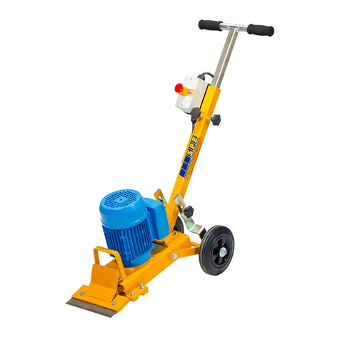
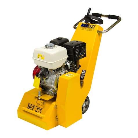
SPE BEF200N User manual

BEF200N
OWNER’S MANUAL AND PARTS BOOK
www.BARTELLGLOBAL.com
Doc. #OIPB-S18001
Orig. Rel. –08/2020
Curr Rev. -00

BEF200N
PARTS BOOK OIPB-S18001
2
www.BARTELLGLOBAL.com
Bartell Morrison Inc.
170 Traders Blvd E
Mississauga, Ontario, Canada
L4Z 1W7
Tel: (647) 953-4100
Fax: (647) 953-4101
Bartell Morrison USA LLC
200 Commerce Drive, Unit A
Freehold, NJ, USA
07728
Tel: (848) 225-8100
Fax: (848) 225-8101
SPE International Ltd
Honeyholes Lane
Dunholme, Lincoln, England
LN2 3SU
Tel: 01673 860709
Fax: 01673 861119
Innovatech
4701 Allmond Ave
Louisville, Kentucky, USA
40209
Tel: (425) 405-9100
Fax: (425) 405-9101
© 2020 Bartell Morrison Inc.
This manual is provided to persons purchasing an SPE machine and may not be
reproduced in part or full without written permission of SPE International Ltd.
This manual provides the basic information required and is only to be used as a guideline.
The SPE machines are manufactured and covered by SPE design registrations granted and
pending. SPE International Ltd reserves the right to alter the equipment design and
specification as required without notice.
Address inquiries or reference permissions care of:
Bartell Morrison Inc., 170 Traders Blvd E., Mississauga, Ontario, Canada, L4Z 1W7
REV.
DATE
DESCRIPTION
APPROVED BY:
00
09/20
Initial Release
AN

BEF200N
PARTS BOOK OIPB-S18001
3
SAFETY PRECAUTIONS
DANGER
EXPLOSION HAZARD
Never operate the machine in an explosive
atmosphere, near combustible materials, or where
ventilation does not clear exhaust fumes.
WARNING
BURN HAZARD
Never come into contact with the engine or muffler
when engine is operating or shortly after it is turned
off. Serious burns may occur.
CAUTION
MOVING PARTS
Before starting the machine, ensure that all guards
and safety devices are in place and functioning
properly.
ATTENTION
READ OWNER’S MANUAL
Read and understand owner’s manual before using
this machine. Failure to follow operating
instructions could result in serious injury or death.

BEF200N
PARTS BOOK OIPB-S18001
4
TABLE OF CONTENTS
ABOUT THIS MANUAL................................................................................................................... 5
SAFETY INSTRUCTIONS ................................................................................................................. 5
START-UP OPERATION .................................................................................................................. 6
GENERAL OPERATION................................................................................................................... 7
ELECTRICAL REQUIREMENTS ......................................................................................................... 8
CUTTER DRUM REMOVAL ............................................................................................................. 9
CUTTER DRUM MAINTENANCE ..................................................................................................... 9
GENERAL MAINTENANCE............................................................................................................ 10
PREVENTATIVE MAINTENANCE AND ROUTINE SERVICE PLAN...................................................... 11
MAINTENANCE CHECKLIST .......................................................................................................... 13
PARTS LIST 1 - SCARIFIER............................................................................................................. 14
GENERAL ASSEMBLY DIAGRAM: BEF200N..................................................................................................................14
GENERAL ASSEMBLY DIAGRAM: BEF200N –PARTS LIST 1..........................................................................................15
PARTS LIST 2 - SCARIFIER............................................................................................................. 16
FASTENERS: BEF200N..................................................................................................................................................16
FASTENERS: BEF200N –PARTS LIST 2 .........................................................................................................................17
ELECTICAL DIAGRAM .................................................................................................................. 18
BEF200N-1...................................................................................................................................................................18
BEF200N-2...................................................................................................................................................................19
BEF200N-2A ................................................................................................................................................................19
Electrical Components ................................................................................................................ 22
BEF200N-1...................................................................................................................................................................22
BEF200N-2...................................................................................................................................................................22
BEF200N-2A ................................................................................................................................................................22
BEF200N-3...................................................................................................................................................................23
Specification Sheet ..................................................................................................................... 24
Noise & Vibration Assessments................................................................................................... 25
BEF200N Electric –TCT Cutters...................................................................................................................................25
BEF200N Electric –Beam Cutters ...............................................................................................................................26
BEF200N Petrol –TCT Cutters.....................................................................................................................................27
BEF200N Petrol –Beam Cutters .................................................................................................................................28
Warranty.................................................................................................................................... 29
Declaration of Conformity........................................................................................................... 30
Conditions of Sale....................................................................................................................... 31

BEF200N
PARTS BOOK OIPB-S18001
5
ABOUT THIS MANUAL
To the best of our knowledge, this manual covers the operation and maintenance of the
BEF200N Scarifier. Before operation of the equipment this manual should be read and
understood by the operator. The safety regulations must be followed at all times, and service
of electrical components should be carried out by authorised personnel.
SAFETY INSTRUCTIONS
Failure to follow these instructions may result in serious personal injury or death. SPE
disclaims all responsibility for damage to persons or objects arising as a consequence of
incorrect handling of the machine and failure to inspect the machine for damage or other
faults that may influence the operation prior to starting work.
•Only trained operatives should be allowed to work the BEF200N.
•All operatives should wear all PPE including ear protection, goggles, an effective dust
mask and boots.
•Never leave the BEF200N unattended while in use.
•An SPE dust vacuum unit is recommended to control dust.
•Never leave the engine/motor running when machine is not in use.
•Always ensure that all power leads are disconnected before attempting to service the
machine. The service of electrical components should be carried out by authorised
personnel.
•Never remove the side plate or belt guard until the cutter drum has come to a complete
standstill.
•Never tip the machine backwards until the cutters have come to rest.
•Never operate the machine outdoors in wet conditions as the electrical components are
not waterproof.
Noise and vibration will occur at various levels dependent on the attachments and work
being completed. SPE have assessments conducted under test conditions detailed in the
operating manual. (See Noise and Vibration Assessments). However, it is recommended
that additional tests are taken on site to provide the operator with accurate information on
using the equipment within the guidelines laid down by the Health & Safety Executive.

BEF200N
PARTS BOOK OIPB-S18001
6
START-UP OPERATION
Check the following prior to starting equipment:
•Condition of the cutter drum assembly.
•All bolts for proper tightness.
•Drive belt condition and tension.
•All plugs and cables for damage.
1. Before starting the machine ensure that the cutter drum assembly is clear of the ground
by raising the quick lift lever so that the cutters are clear of the ground. Adjust the
handlebar to a comfortable height and position.
2. Connect the power supply or IF gas/petrol version then check for fuel.
3. Connect the vacuum hose to the dust port at the rear of the machine if a dust control
vacuum is being used.
STEP 4 -ELECTRIC VERSIONS, STEP 5 GAS/PETROL VERSIONS
4. BEF200N-1 –110V 50Hz Single Phase
Start the motor by turning the switch on the panel to the start position. Hold for 2-3
seconds for the motor to start and release. The switch will return to its run position. To
stop the machine, turn the switch anti-clockwise.
BEF200N-2 –230V 50Hz Single Phase
Start the motor by pressing the green start button on the panel. To stop the machine,
press the red stop button.
BEF200N-3 –400V 50Hz 3 Phase
Start the motor by pressing the green start button on the panel. To stop the machine,
press the red stop button.
BEF200N-2A –230V 60Hz Single Phase (N.A)
Start the motor by pressing the black button on the electrical box. To stop the machine,
press the red stop button.
5. BEF200N-4 –GAS/PETROL
Start engine by following the instructions in the engine manual. Once engine is on and
running then close the choke and throttle to full speed.
6. To start cutting gently lower the quick lift lever to return the cutting drum to the operating
position. Turn the handwheel of the fine height adjustment until the desired depth of cut
is achieved.

BEF200N
PARTS BOOK OIPB-S18001
7
GENERAL OPERATION
•Excessive downward pressure on the cutters may marginally improve the work
rate/finish but the definite increase in wear rates on the cutter drum assembly, machine
components and overloading the motor is the negative result.
•Two light passes are quicker and more cost effective than one slow heavy pass. Tests
have proven conclusively that heavy downward pressure reduces cutter and drum life by
over 50%.
•To remove dust, connect an industrial dust collector or vacuum to the 50mm port at the
rear of the machine. We recommend SPE Dust Control units for near-100% dust control.
In the absence of a dust control unit it is acceptable to spray water onto the surface or
to feed water down the vacuum port. Cutter drum assembly life is increased by around
10% when operating the machine in this way.
•Electrical motors and switches are not waterproof, take care to protect them from
splashes.
•The BEF200N is normally operated in a forward direction. The operator varies the speed
of travel to determine the final finish, having already pre-set the depth control. It is
permissible to operate the machine with a backwards and forwards action. Each pass
should be overlapped to produce a uniform finish.

BEF200N
PARTS BOOK OIPB-S18001
8
ELECTRICAL REQUIREMENTS
The BEF200N machine is supplied with a specially commissioned electric motor and starter
switch assembly. Each unit is fully tested, and the safety overload relays have been
calibrated and set according to the manufacturer’s specifications. In the event of the
malfunction on a new machine the owner should first check that the power supply on-site is
suitable and adequate.
BEF200N-1 –110V 50Hz Single Phase
•Motor requires a 110v, 15 Amp supply –4 mm 3 core wire.
BEF200N-2 –230V 50Hz Single Phase
•Motor requires a 230v, 16 Amp supply - 7.5 mm 3 core wire.
BEF200N-2A –230V 60HZ Single Phase (North America)
•Motor requires a 230v, 20 Amp supply –12 awg 3 core wire.
BEF200N-3 –400V 50Hz 3 Phase
•Motor requires a 400v, 16 Amp supply - 7.5 mm 4 core wire.
*See Electrical Specifications for more information.

BEF200N
PARTS BOOK OIPB-S18001
9
CUTTER DRUM REMOVAL
1. Isolate the power supply and ensure the cutter drum has stopped rotating.
2. Raise the Quick-Lift lever so that the cutters are clear from the ground.
3. Loosen the four 8mm set screws and remove the side plate. This cover can stick
when brand new, so it may be necessary to lever off the plate with a screwdriver.
4. With the side plate removed the cutter drum will simply slide off the drive shaft.
5. Fitting a new cutter head is simply a reversal of the steps 1-4. Ensure that the four
8mm set screws are always tight.
CUTTER DRUM MAINTENANCE
When changing a cutter drum always check that the flail shafts are not excessively worn
with pronounced grooves and that the centres of cutters and spacers are not elongated or
beginning to mushroom. The screws which hold the drum end plates in position must be
tight and in good condition.
It is expensive and false economy to run the cutter drum components until they break. Try
to establish a routine for replacing wear parts before they cause problems. Remember that
the drum assembly is hitting concrete with great force 1,800 times every minute, therefore
expenditure on consumables must be expected and built into all job costing.
While changing the drum the condition of the drive shaft and side plate bearings should be
checked. If there is any roughness, side-play, or leakage of grease is detected, new
bearings should be fitted. Lightly oiling the drive shaft will prevent a build-up of rust which
could cause difficulty when changing the drum.
The drive shaft is manufactured from high quality steel and then heat treated to produce the
special properties required. The shaft is extremely strong and virtually unbreakable when
used as intended. If, however, sideways pressure is exerted on the shaft while it is not
supported by the side plate bearing, then it can be bent.
With the drum removed check that the vacuum port is free from blockages and that the dust
skirt is in good condition.

BEF200N
PARTS BOOK OIPB-S18001
10
GENERAL MAINTENANCE
Prior to any maintenance or adjustment, you must isolate the power supply.
AFTER USE:
Clean the machine to remove all the build up of dust and surface residue. If using a hose
pipe or pressure washer take care that water is not directed onto electrical components and
switches.
(Note: Motors and switches are not waterproof)
Ensure the height adjustment thread is cleaned and then lightly oiled. Periodically it should
be removed and the female, threaded section cleaned out and oiled regularly to maintain a
light, smooth height adjustment.
The HTD drive belt will give a long and trouble free operating life if basic procedures are
followed.
Daily, check the drive pulleys for build up of deposits and trapped stones. Check the belt
and teeth for surface cuts and cracks, once the surface of the belt is damaged it will soon
fail. Build up of dirt in the pulley teeth causes two problems: The belt becomes tight and as
the teeth can no longer fully mesh properly, all the power is transmitted through the tip of the
teeth with obvious negative results.
The drive belt is tensioned by two eye bolts at the front of the motor. It is important that the
drive belt is not over tensioned. It should be tight enough for all teeth to make full contact
but should allow a little movement to allow for "self alignment".
Serious damage could be caused to the drive shaft, drive shaft bearings and drive motor if
the belt is excessively tight. Generally, when the motor is started and run, a tight belt can be
detected by a low hum/whistle.
Note: Never operate the BEF200N without a belt guard.
All components should be checked daily for tightness and the drive belt for tension.

BEF200N
PARTS BOOK OIPB-S18001
11
PREVENTATIVE MAINTENANCE AND ROUTINE SERVICE PLAN
This SPE BEF200N has been assembled with care and will provide years of service.
Preventative maintenance and routine service are essential to the long life of your Scarifier.
Your dealer is interested in your new machine and has the desire to help you get the most
value from it. After reading through this manual thoroughly, you will find that you can do
some of the regular maintenance yourself. However, when in need of parts or major service,
be sure to see your Bartell Morrison dealer. For your convenience, we have provided this
space to record relevant data about your SPE BEF200N. When in need of parts or service
be prepared to provide your Scarifier serial number. Locate the serial number now and
record in the space below.
Date Purchased:
Type of Machine:
Dealer Name:
Model:
Dealer Phone:
Serial Number:
Replacement Parts Used
Maintenance Log:
Part No.
Quantity
Cost
Date
Date
Operation

BEF200N
PARTS BOOK OIPB-S18001
12
ROUTINE SERVICE SCHEDULE
Routine Service Intervals
Each
Use
First
months
or 10
hrs
Every 3
months
or 25 hrs
Every 6
months
or 50
hrs
Every
year or
100 hrs
Every 2
years or
300 hrs
General Inspection
Warning Stickers
Check
O
O
O
O
O
O
Test run:
Operation
O
O
O
O
O
Engine
Engine Oil
Check level
O
Change
O
O
Spark Plug
Check-adjust
O
Replace
O
Timing Belt
Check
After every 300 hrs (2) (3)
Cooling Fins
Check
O
Air Cleaner (2)
Check-clean
O (1)
O
Replace
O
Air Intake Line
Check
O
Replace
2 yrs
Nuts, bolts,
fasteners
Check
O
Idle Speed
Check-adjust
O (2)
Valve Clearance
Check-adjust
O (2)
O
Combustion
Chamber
Clean
After every 300 hrs (2)
Fuel Filter
Clean
O (2)
Fuel Tank
Clean
O (2)
Fuel Tubes
Check
Every 2 years (Replace if necessary) (2)
Oil Tube
Check
Every 2 years (Replace if necessary) (2)
Drum/Cage
Drum
Check
Cutters
Check/Replace
when worn out
Flail Shafts
Machine Frame/Body
Nuts and Bolts
Belt
Height adjust
mechanism
Bearings
Drive Shaft
Wheels
(1) Service more frequently in dusty areas
(2) Refer to engine owner’s manual for servicing instructions and a detailed maintenance
schedule. Some items should be serviced by your servicing dealer, unless you have
the proper tools and are mechanically proficient. Refer to the Honda shop manual for
service procedures
(3) Check that there is no crack and abnormal wear-out in the belt, and replace if it is
abnormal

BEF200N
PARTS BOOK OIPB-S18001
13
MAINTENANCE CHECKLIST
DAILY: (or every 8hrs to 10hrs)
•Check the cutters.
•Check the flail shafts.
•Check all nuts and bolts for tightness.
•Check the belt tension.
•Check the plugs and cables.
•Check engine oil.
•Check Air Filter.
•Check for any recommendations in Honda Service Manual.
WEEKLY:
•Grease all moving parts on the height adjustment mechanism.
•Remove the side plate.
•Check the drum.
•Check the drive shaft bearings.
•Check the drive bush.
•Check the drive shaft.
•Check the support wheels and grease.
MONTHLY:
•Strip down fully the winding mechanism.
•Clean all threads and re grease.

BEF200N
PARTS BOOK OIPB-S18001
14
PARTS LIST 1 - SCARIFIER
GENERAL ASSEMBLY DIAGRAM: BEF200N

BEF200N
PARTS BOOK OIPB-S18001
15
GENERAL ASSEMBLY DIAGRAM: BEF200N –PARTS LIST 1
Item #
Part #
Description
QTY
Remarks
101
20025
BEF200N DRUM
1
102
6204
BEARING, 47MM X 20MM
4
103
7034
KNOB GRIP
1
104
9102
SIDE PLATE SPACER
1
105
9106
DUST SKIRT
1
106
9107
FRONT AXLE
2
107
9110
REAR AXLE ASSEMBLY
1
108
9113A
KEY, 16MM X 4MM
1
109
9114
HEX DRIVER BUSH
1
110
9115
SIDE PLATE BEARING HOUSING
1
111
9116
BEARING HOUSING ASSEMBLY
2
112
9117
SWING ARM BOSS
2
113
9118
SWING ARM PIN
2
114
9119
BUSHING, 26MM X 20MM
1
115
9120
WHEEL, 75MM
1
116
9121
WHEEL, 128MM
2
117
9122
YOKE & CLEVIS, M12
1
118
9123
BEARING, 55MM X 30MM
1
119
9124
BEARING, 47MM X 25MM
1
120
9125
DRIVE SHAFT SPACER
1
121
9126
PULLEY (GAS)
1
122
9127
PULLEY (EU)
2
123
9128
DRIVE PULLEY
1
124
9131
KEY, 30MM X 8MM
1
125
9132
CIRCLIP, 50MM
1
126
9133
CIRCLIP, 28MM
1
127
9135
HAND WHEEL WITH KNOB
1
128
9137
BELT (ELECTRIC & GAS)
1
129
9138
BELT GUARD
1
130
9140
DRIVE SHAFT
1
131
-
HONDA GX160 ENGINE
1
132
-
ELECTRIC MOTOR
1
133
9158
SPACER (GAS PULLEY)
1
134
9200
CHASSIS
1
135
9201
RIGHT SIDE PLATE
1
136
9202
MOTOR PLATE
1
138
9203
HANDLE ASSM (ELECTRIC VERSIONS)
1
138
9205
HANDLE ASSM W/SWITCH (GAS/PETROL VERSIONS)
1
139
9206
VACUUM PORT
1
140
9301
HEIGHT ADJUST BLOCK
1
141
9302
HEIGHT SCREW
1
142
9303
MAIN ROD
1
143
9304
PITCH BLOCK
1
144
9305
ADJUSTABLE HEIGHT TUBE
1
145
9308
PITCH HANDLE
1
146
9309
PITCH HANDLE ROD
1
147
9310
HANDLE SLEEVE
1
148
9311
WEAR PLATE
1
149
9312
HANDLE CAP
1
150
9313
HANDLE PLATE
1
151
9314
HANDLE TOP PLATE
1
152
9315
M8 LOCK HANDLE
1
153
9316
M8 SWING BOLT
2
154
9317
ROD END
1
155
9318
BUSHING
2
156
9321
SPACER
1
*USE PREFIX 90 WHEN ORDERING IN NORTH AMERICA*

BEF200N
PARTS BOOK OIPB-S18001
16
PARTS LIST 2 - SCARIFIER
FASTENERS: BEF200N

BEF200N
PARTS BOOK OIPB-S18001
17
FASTENERS: BEF200N –PARTS LIST 2
Item No.
Part Number
Description
Qty.
201
10999
HHCS, M8-1.25 x 20mm
21
202
11614
Lock Washer, M8
33
203
11667
Flat Washer, M8
40
204
10452
HHCS, M8-1.25 x 40mm
4
205
41516
Flat Washer, M10
7
206
11622
Hex Nut, M10
4
207
11621
Lock Washer, M10
5
208
11619
HHCS, M8-1.25 x 25mm
8
209
10193
Hex Nut, M8
10
210
11746
HHCS, M6-1.0 x 16mm
4
211
14447
Flat Washer, M6
10
212
11620
Lock Washer, M6
14
213
11618
SHCS, M6-1.0 x 12mm
4
214
13348
HHCS, M10-1.5 x 25mm
1
215
10881
HHCS, M12-1.75 x 35mm
2
216
10993
Flat Washer, M12
4
217
10735
Lock Washer, M12
2
218
64003
Repair Washer, M8
3
219
31176
HHCS, M10-1.5 x 20mm
2
220
11731
HHCS, M8-1.25 x 30mm
1
221
51058
HHCS, M6-1.0 x 20mm
6
222
11772
SHCS, M8-1.25 x 25mm
2
223
10784
HHCS, M8-1.25 x 45mm
1
224
10730
Hex Nut, M12
1

BEF200N
PARTS BOOK OIPB-S18001
18
ELECTICAL DIAGRAM
BEF200N-1

BEF200N
PARTS BOOK OIPB-S18001
19
BEF200N-2

BEF200N
PARTS BOOK OIPB-S18001
20
BEF200N-2A
Table of contents
Other SPE Lawn And Garden Equipment manuals
Popular Lawn And Garden Equipment manuals by other brands

Nilfisk-Advance
Nilfisk-Advance Water Inlet Suction Hose Directions for use

New England Arbors
New England Arbors The Windsor Long Planter Box Assembly instructions

Gibson
Gibson 310003 instruction manual

Husqvarna
Husqvarna AUTOMOWER 420 Operator's manual

Stihl
Stihl BF-KM instruction manual

Vstreet
Vstreet UDP-4812 Assembly instructions

Premier designs
Premier designs Wing Garden Lighthouse Assembly instructions

GreenWorks Pro
GreenWorks Pro ULTRA POWER EA60L00 Operator's manual

VELAMP
VELAMP MK040 instruction manual

CAMPAGNOLA
CAMPAGNOLA T-REX 160-240 Use and maintenance manual

MASSEY FERGUSON
MASSEY FERGUSON MF1746 Service manual

Lifely
Lifely Agrumino Lemon Guide