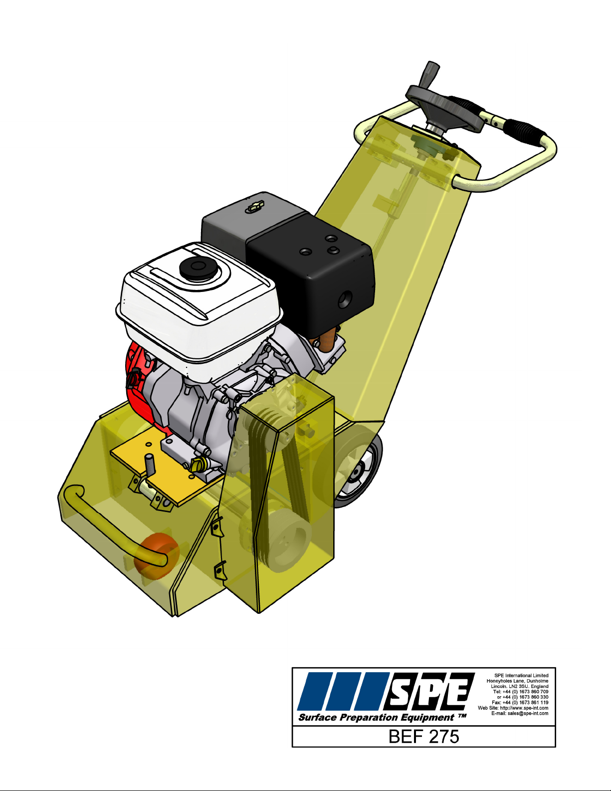
SPE BEF 275 User manual

BEF275-1
Operating Manual
This manual is provided to persons purchasing an
SPE machine and may not be reproduced in part or full
without written permission of
SPE International Ltd.
This manual provides the basic information required
and is only to be used as a guideline.
The SPE machines are manufactured and covered by
SPE design registrations granted and pending.
SPE International Ltd reserves the right to alter the
equipment design and specification as required
without notice.
The SPE product range is subject to amendment and
improvement as a result of on going research
Honeyholes Lane, Dunholme, Lincoln LN2 3SU, England
Tel: +44 (0) 1673 860709 Fax: +44 (0) 1673 861119
Email: sales@spe-int.com

BEF275-1
Operating Manual
BEF275-1 OPERATING MANUAL
This manual covers to the best of our knowledge, the operation and maintenance of the BEF275
Multi-plane. Before operation of the equipment the manual must be read and understood by the
operator. The safety regulations must be followed at all times. Failure to follow these instructions
could result in damage to the machine and/or serious personal injury or death.
WARNING
Failure to follow this instruction may result in serious personal injury or death. SPE disclaims all
responsibility for damage to persons or objects arising as a consequence of incorrect handling of
the machine, failure to inspect the machine for damage or other faults that may influence the
operation prior to starting work, or failure to follow the safety regulations listed or applicable to the
job site.

BEF275-1
Operating Manual
INDEX
Page No
1 Starting Work
General Operation
2 Petrol Engine
Dust Control
3-4 Maintenance
5 Basic Maintenance Checklist
6 Safety
7-8 Accessories
9 -11 Cutter Drum Set Up
12 Spare Parts Breakdown
13 Body Components
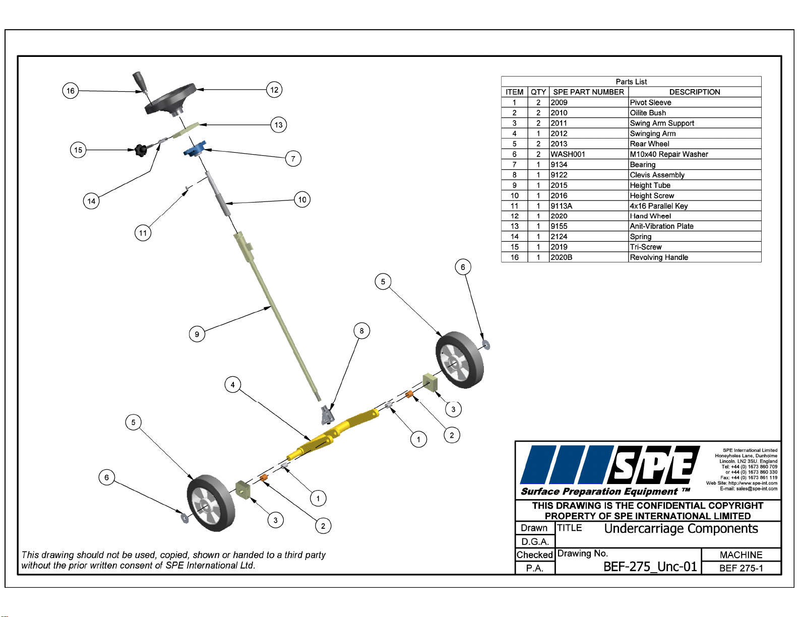
14 Undercarriage Components
15 Drive Components
16 Specifications
17 Noise and Vibration Assessment
18 Warranty
19 Declaration of Conformity
20 Conditions of Sale

BEF275-1
Operating Manual
STARTING WORK
Check the following prior to starting the equipment
- Check the condition of the cutter drum assembly
- Check all nuts and bolts for tightness
- Check the drive belt condition and tension
- Check the drive pulleys are clean and undamaged
- Check the engine oil level
- Check the air filter is clean
1. Before starting the machine, ensure the cutter drum assembly is clear of the ground.
2. Adjust the handlebars to a comfortable height and position.
3. Connect the dust control hose if a vacuum is being used
4. Start the engine. See manufacturers manual for further guidance
Slowly rotate the hand wheel until the cutters make contact with the surface to be prepared. It is
essential that the cutters are not lowered too far and too hard onto the surface as seriousdamage
could be caused to the machine and the cutter drum assembly.
5. Lock the hand wheel using the locking screw when the correct cutting depth is set.
GENERAL OPERATION
The cutters must be allowed to "float" on the cutter shafts without downward pressure. This
floating action allows the cutters to perform as the designer intended i.e. as flails rather than as
grinders or picks.
The machine should operate smoothly with a minimum of vibration. When the depth of cut
is correctly set, very little effort should be required to operate the machine backwards and
forwards - the recommended method of operation.
Excessive downward pressure on the cutters may marginally improve the work rate/finish but the
definite increase in wear rates on the cutter drum assembly and machine components is the
negative result. Remember two light passes are quicker and more cost effective than one slow
heavy pass. Tests have proven conclusively that a heavy downward pressure reduces the cutter
and drum life by over 50%.
The BEF275 is normally operated in a forward direction, the operator variesthe speed of travel to
determine the final finish having already pre-set the depth control. It is recommended to operate
the machine with a backwards and forwards action, while maintaining overall forward motion.
Each pass should be overlapped to produce a uniform finish.
1

BEF275-1
Operating Manual
PETROL ENGINE
This manual should be read in conjunction with the Owners Manual of the petrol engine. The
engine is designed to give safe and dependable service if operated according to the instructions.
Read and understand the Owners Manual before operating the engine. Failure to do so could
result in personal injury or equipment damage.
Note: Avoid tipping the BEF275 backwards, when fitted with the Honda
GX340 engine, for longer than a minute. The engine oil can run into the cylinder head
causing the piston to hydraulically seize. In the event of a hydraulic seizure never try to
force the engine to turn over. Remove the spark plug and slowly turn the engine over by
hand. Ensure the ignition and fuel are turned "off". If this method is unsuccessfulthenthe
engine should be returned to the manufacturer.
DUST CONTROL
To remove dust, connect an industrial dust collector or vacuum to the 50mm port at the rearof the
machine. We recommend the SPE VAC316 for almost 100% dust control. In the absence of a
dust control unit it is acceptable to spray water onto the surface or to feed water down thevacuum
port. Cutter drum assembly life is increased by around 10% when operating the machine in this
way.
2

BEF275-1
Operating Manual
MAINTENANCE
Prior to any maintenance or adjustment, stop the engine.
After use: Clean the machine to remove all build up of dust and surface residues. If usingahose
pipe or pressure washer take care that water is not directed onto the engine and switches.
Note: Engine and switches are not waterproof
Drum removal:
Remove the bolts on the side plate and then screw two of the bolts back into the twotappedholes
in the side plate. Continue winding these bolts in and this will push the side plate off the dowel
pins. Remove the side plate. Pull out the cutting drum - the drive shaft may come out with the
drum assembly as this is only a push fit into the drive bush.
Fitting a new cutter drum is simply a reversal of the above procedure, a little care must be takento
align the drive shaft, cutter drum and support end drive bush.
EXCESSIVE FORCE IS NOT NEEDED TO REFIT THE CUTTER DRUM.
Cutter Drum Maintenance:
When changing the cutter drum always check that the flail shafts are not worn with pronounced
grooves and also that the centres of cutters and spacers are not elongated and beginning to
"mushroom". The drum assembly is hitting concrete with great force at over 1,600 times every
minute! Expenditure on consumables must be expected and built into all job costing.
While changing the drum, the condition of the drive shaft and side plate bearings should be
checked. If any roughness, side play or leakage of grease is detected, then new bearings should
be fitted. Lightly oiling the drive shaft will prevent a build up of rust which could cause difficulty
when changing the drum. At the same time check the belt tension and condition, also checking
the pulley grooves are clean and undamaged.
The drive shaft is manufactured from high quality steel and then heat treated to produce the
special properties required. The shaft is extremely strong and virtuallyunbreakablewhenusedas
intended. If, however, sideways pressure is exerted on the shaft while not supportedatbothends
then it can be damaged.
With the drum removed, check that the vacuum port is free from blockages and that the dust skirt
is in good condition.
Remove all build up and deposits of material from the under side of the drum housing. On certain
applications, e.g. the removal of damp self levelling compounds, it may be necessary to clean
away deposits hourly! Failure to do so could result in overload of the drum assembly, engine and
the drive belts.
Cont’d ………
3

BEF275-1
Operating Manual
Height Adjustment Maintenance
Ensure the height screw thread is cleaned and then lightly oiled. Periodicallyitshouldbe removed
and the female, threaded section cleaned out and oiled. At thesametimetheself aligningbearing
should be greased
The clevis pin should be oiled regularly to maintain a light, smooth height adjustment.
General Maintenance
Great care should be taken to ensure the belts have the correct tension and also the correct
alignment. Serious damage could be caused to the drive shaft, drive shaft bearings and engine if
the belts are excessively tight.
Note: Never operate the BEF275 without a belt guard
All components should be checked daily for tightness and the drive belts for correct tension.
Check the individual manufacturers service recommendations for full details on the engine.
4

BEF275-1
Operating Manual
BASIC MAINTENANCE/CHECKLIST
DAILY: (or every 8hrs to 10hrs)
Check the cutters
Check the flail shafts
Check all nuts and bolts for tightness
Check the belt tension and condition
Check engine oil daily
Change the engine air filter if not using vacuum unit
See engine manufacturers maintenance details before starting engine.
WEEKLY:
All the above with following:-
Grease all moving parts on the height adjustment mechanism
Remove the side plate
Check the drum
Check the bearings
Check the drive bushes
Check the drive shaft
Check the support wheels and grease.
MONTHLY:
All the above with following:-
Strip down fully the winding mechanism
Clean all the threads and re-grease
5

BEF275-1
Operating Manual
SAFETY
Only trained operatives should be allowed to work the BEF275.
All operatives should wear ear defenders, goggles and an effective dust mask.
Note; It is possible that the noise level produced by the BEF275 could exceed 90dbA. Personal
noise protection must be worn.
To control dust, it is recommended that an SPE dust control unit is used in conjunction with the
machine.
Never leave the BEF275 unattended while in use. Always stop the engine and set the height
adjustment fully up before leaving the machine.
Always ensure that the engine switch is in the off position and disconnect the spark plug cap
before attempting to service the machine. Never remove the side plate or belt guard until the
cutter drum has come to a complete standstill. Never tip the machine backwardsuntil the cutters
have come to rest.
Never operate a petrol engine BEF275 inside or in a poorlyventilatedarea. Carbonmonoxidegas
is emitted.
Never refill the petrol tank whilst inside a building.
Always stop the engine before refuelling.
Never refill the petrol tank when the engine is hot.
Never release the machine from operators control during use. The cutting action of the
drum will propel the machine forward at high speed. If the operator has anyproblem whilst
operating the machine, turn the red stop button on the engine or tip backwards.
Noise and vibration will occur at various levels dependant on the attachments and work being
completed. SPE have assessments conducted under test conditions detailed in the operating
manual. (See page 17). However it is recommended that additional tests are taken on site to
provide the operator with accurate information on using the equipment within the guidelines
laid down by the health and safety executive.
6
BEF275-1
Operating Manual
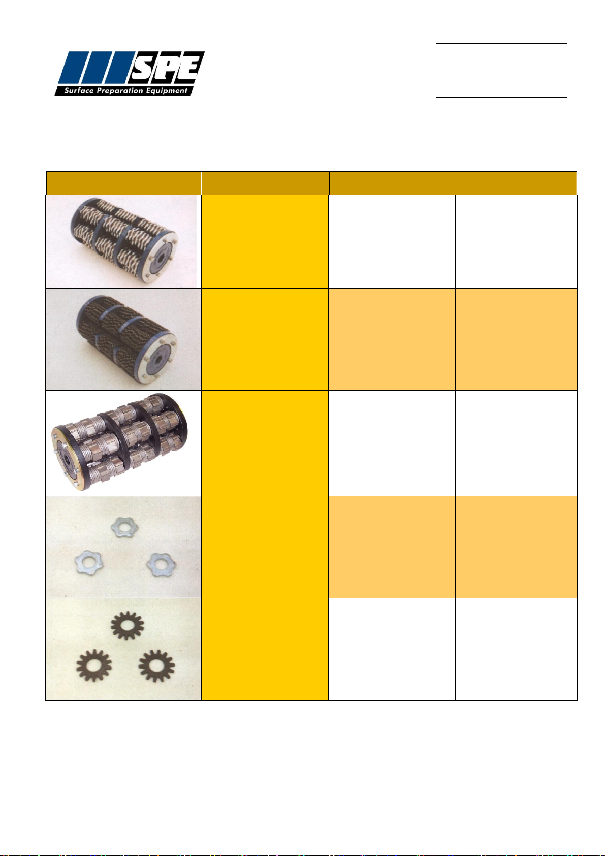
Part No
Description
Application
27501
Heavy duty drum complete with
T.C.T cutters and spacers.
For all concrete texturing,
scabbling planing and grooving
applications. Removal of bridge
deck and car park membranes,
heavy industrial contamination,
epoxy coatings and road
markings, reducing concrete. Use
on heavy applications for longer
life with higher output.
27502
Heavy duty drum complete with
beam flails.
For the removal of paint, laitence
and coatings from floors. De-
rusting and de-scaling ship decks.
Also used for removing build up of
grease, dirt and ice deposits.
Keying of concrete when a fine
textured surface is required
27504
Heavy duty drum complete with
milling cutters and spacers
For removal of thermoplastic
road/runway markings. Very
efficient and cost effective with
none of the problems associated
with burning off thermoplastics.
Also for the removal of bituminous
and rubber deposits.
60600
T.C.T Cutter: 6 point hardened steel
cutter with tungsten carbide inserts
For all concrete texturing,
scabbling planing and grooving
applications. Removal of bridge
deck and car park membranes,
heavy industrial contamination,
epoxy coatings and road
markings, reducing concrete. Use
on heavy applications for longer
life with higher output.
60120
Beam cutter: Heat treated steel
cutter
For the removal of paint, laitence
and coatings from floors. De-
rusting and de-scaling ship decks.
Also used for removing build up of
grease, dirt and ice deposits.
Keying of concrete when a fine
textured surface is required.
ACCESSORIES
7
BEF275-1
Operating Manual
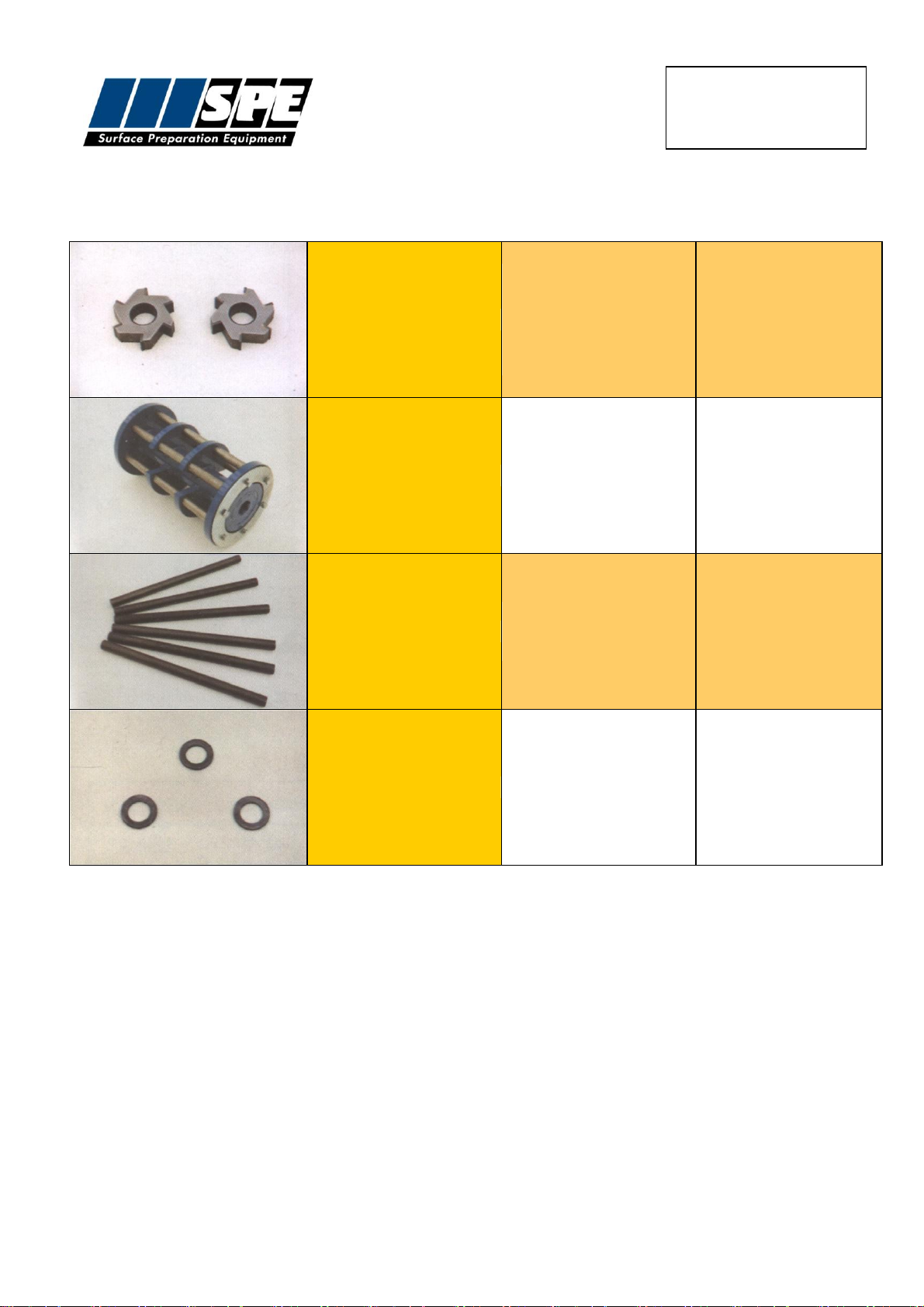
BEF275-1 ACCESSORIES
60620
Milling Cutter: Tipped with Tungsten
carbide.
For the removal of thermoplastic
road/runway markings, rubber
based deposits and cold plastic
coatings from asphalt and
concrete.
27500
Heavy duty drum complete with flail
shafts.
For use with various cutter
configurations.
27518
Heavy duty flail shaft.
Hardened cutter shaft.
40240
Spacing washer.
Hardened spacing washer.
8

BEF275-1
Operating Manual
12

BEF275-1
Operating Manual
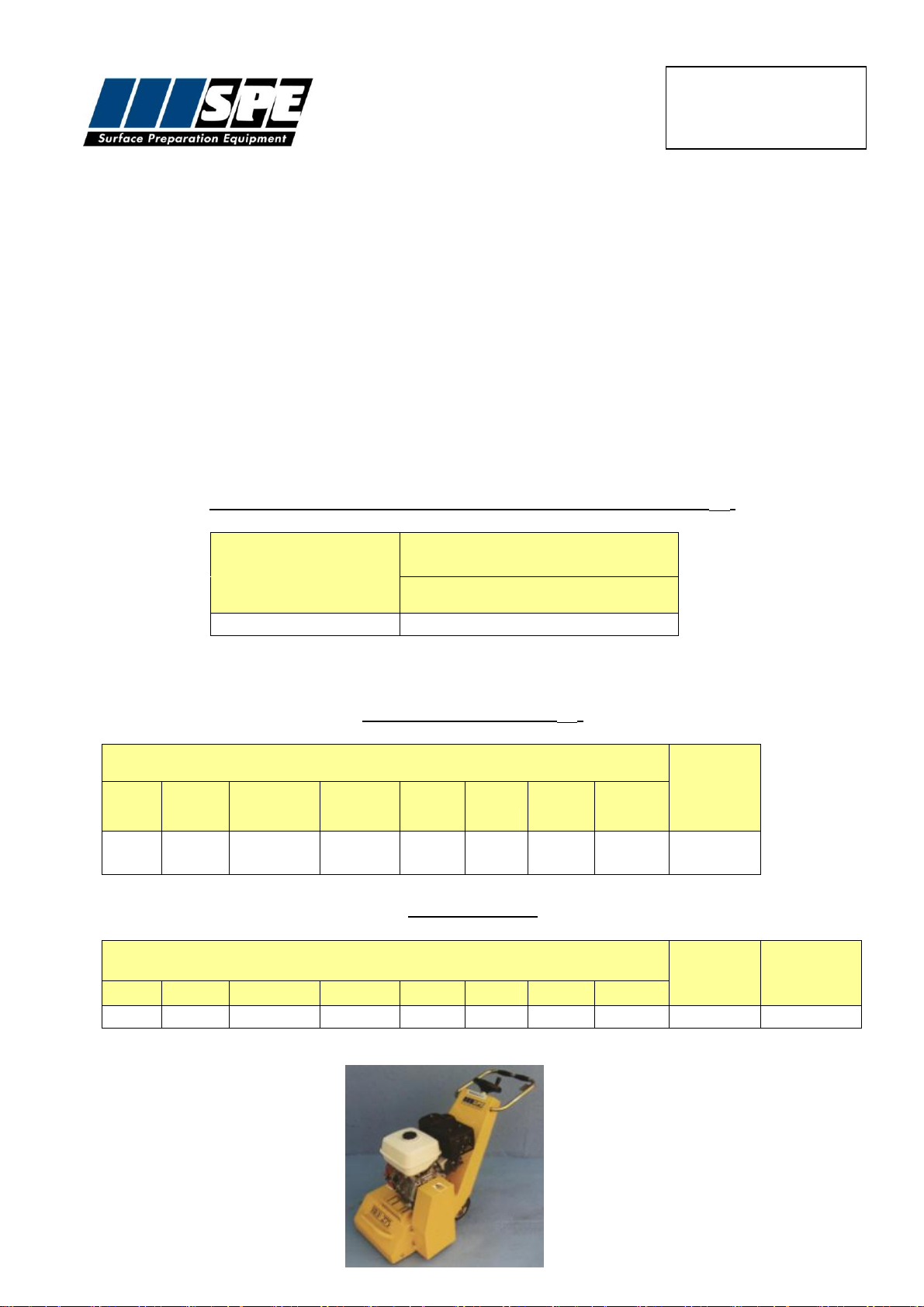
SPECIFICATION SHEET
Specifications
Type
BEF275
Petrol
Part Number
BEF275-1
Power Output
11hp
Voltage
-
Cycles
Cutter Head Speed (rpm)
1530/1640
Machine Dimensions:
(mm)
Length
Width
Height
Weight (kg)
1220
511
900
145
Working width of cutters (mm)
275
Working distance from walls (mm)
65
Engine/Motor speed (rpm)
3000
16
BEF275-1
Operating Manual
RECORD OF NOISE AND VIBRATION ASSESSMENT
Manufacturer:
SPE
Type:
Scarifier
Model No.
BEF275-1 Petrol
Motor:
Honda GX340 11HP
Operation :
Concrete floor surface
Inserted Tool:
TCT cutters
Running Conditions:
2910 rpm
HAV Note:
Operc
HAND-ARM VIBRATION
Frequency Weighted Energy Equivalent Accelerations (ah,w)
Measurement
Position
Acceleration (m/s2)
Vector Sum
Handle
5.3
NOISE LEVELS
Sound Power Level (LWA)
LWA at Octave Band Centre Frequency (Hz)
Sound
Power
Level
LWA
63
125
250
500
1000
2000
4000
8000
69.2
87.6
93.1
97.1
102.2
100.
3
96.9
89.9
106.0
Operator's Ear
LAeq,T at Octave Band Centre Frequency (Hz)
Overall
Level
(LAeq,T)
LPeak
dB(C)
63
125
250
500
1000
2000
4000
8000
54
71.2
76.3
85.3
89.7
87.7
83.1
75.9
92.3
107.3
17
BEF275-1
Operating Manual
WARRANTY
The standard warranty period of this equipment is 12 months from the date below in accordance
with the company Conditions of Sale (copy attached).
Warranty start date:
As despatch date
Model:
BEF275-1
Serial no:
Customer name:
Customer Address:
Manufacturer:
SPE International Ltd
Honeyholes Lane
Dunholme
Lincoln
LN2 3SU
England
Telephone:
+44 (0) 1673 860709
Fax:
+44 (0) 1673 861119
Email:
sales@spe-int.com
Web site:
www.spe-int.com
18
BEF275-1
Operating Manual
DECLARATION OF CONFORMITY
WE
SPE INTERNATIONAL LTD
OF
Honeyholes Lane
Dunholme
Lincoln
LN2 3SU
DECLARE that under our sole responsibility for the supply/manufacture of the product
(Description/name) BEF275 Multiplane
(Model/type) BEF275-1
to which this declaration relates is in conformity with the following standards and other normative
documents following the provisions of Directive 2006/42/EC.
....................................................
Brian Jacklin –Technical Manager
SPE INTERNATIONAL LTD
19

BEF275-1
Operating Manual
The quotation overleaf and any order placed following such quotation are subject to the following conditions of sale in which SPE
International Limited is referred to as the “Company”.
1. Validity of quotation
No order received from a customer by the Company shall constitute a contract until accepted in writing by the Company.
2. Prices
Prices quoted by the Company are firm for 30 days only or until previously withdrawn. Unless otherwise stated all prices are exclusive
of any applicable Value Added Tax for which the customer shall be additionally liable to the Company.
3. Delivery
Delivery periods and dates are given in good faith but are not the subject of any warranty or condition and time shall not be of the
essence of the contract in these respects. No liability will attach to the Company if delivery periods or dates are not met for any
reason whatsoever.
4. Payment
Save as may otherwise be agreed in writing the customer shall pay the price in full on or before the estimated delivery date
whereupon the Company shall raise a receipted invoice. Each invoice includes an Overdue Account Levy of 5% of the total invoice
value inclusive of VAT. Subject to payment in full being made on or before the due date a sum equal to the Overdue Account Levy
shall be credited to the customers account with the Company. Until such time as payment in full has been made the Company shall
be under no obligation to allow or effect of any goods to the customer.
5. Warranty
The Company warrants that all goods supplied by it will correspond to their specifications and will be free from defects in materials or
workmanship for a period of 12 months from the date of delivery. The Company’s obligation in the event of a breach of this warranty
is limited to the repair or replacement of any defective goods which shall be returned at the cost and expense of the customer to the
Company. This warranty is given in lieu of all the other warranty or conditions expressed or implied (whether by statute or otherwise)
and is subject to the following conditions:-
5.1 Claims must be notified in writing to the Company within seven days from the date of delivery or (where the defect is not
apparent on reasonable inspection) as soon as practicable after discovery of the defect.
5.2 The Company shall be under no liability in respect of any defect in the goods arising from any drawing, design or specification
supplied by the customer.
5.3 The Company shall be under no liability if the defect or failure in the reasonable opinion of the Company arises from wilful
damage or misuse, negligence by the customer or any third party. Failure to follow the Company instructions, usage of non-
recommended parts and materials, alteration or repair of the goods without the prior approval of the Company or non-recommended
maintenance.
5.4 The Company shall be under no liability if the price for the goods has not been paid by the due date for payment.
5.5 The above warranty does not extend to:-
5.5.1 Parts, materials or equipment not manufactured by the company in respect of which the customer shall be entitled only to the
benefit of any such warranty or guarantee as is given by the manufacturer to the Company.
5.5.2 Any component part of the goods or associated parts coming into contact with abrasive elements or dust within surface
Preparation equipment.
5.5.3 Fair wear and tear of moving parts within the goods.
5.6 Except in the case of death or personal injury caused by the Company negligence, the Company shall not be liable for any
consequential loss or damage (whether for loss of profit or otherwise) or other claims for consequential compensation.
6. Carriage
Packing, carriage and insurance charges in respect of delivery of the goods to the customer will be charged to the customer at cost to
the company.
7. Damage in Transit
The company does not accept any liability for loss or damage to the goods while in transit to the customer.
8. Risk
The risk in the goods shall pass to the customer on delivery to the customer or (if earlier) when possession of the goods is taken by a
carrier for delivery to the customer.
9. Force Majeure
The Company shall not be liable to the customer or be deemed to be in breach of any contract with the customer by reason of any
delay in performing or any failure to perform any obligation of the Company obligation in relation to the goods if the delay or failure
was due to force majeure or to any other cause beyond the Company’s reasonable control.
10. Reservation of Title
The goods sold under these conditions shall remain the absolute property of the Company and legal title in the goods shall remain
vested in the Company until payment in full of all amounts invoiced or due to the Company in respect of the goods. If the customer
shall enter into liquidation have a winding up order made against it or have a Liquidator, receiver, administrator or administrator
receiver shall be appointed over its assets, income or any part there of before the property in the goods has passed in accordance
with this condition the Company shall be entitled immediately after giving notice of its intention to repossess any goods to enter upon
the premises of the customer with such transport as may be necessary and to repossess any goods to which it has title under this
condition. No liquidator, receiver, administrator or administrative receiver of the customer shall have authority to sell goods to which
the Company has title without the prior written consent of the Company.
11 Insolvency of Customer
If the customer being a body corporate, shall pass a resolution or suffer an order of the Court to be made for winding –up, or if a
Receiver, Administrator or Administrative Receiver shall be appointed or, being an individual or partnership, shall suspend payment ,
propose or enter into any composition or arrangement with his or their creditors, or have a bankruptcy order made against him or
them, then the Company shall have the right, without prejudice to any other contract with the customer, not to proceed further with the
contract and shall be entitled to charge for work already carried out ( whether completed or not) and for goods and materials already
purchased for the customer such charge to be an immediate debt due from the customer.
12. Patent Rights, etc
The acceptance of a quotation includes the recognition by the customer of the Company under any patents, trademarks, registered
designs or other intellectual property rights relating to the goods and the customer undertakes that patent numbers, trademarks or
other trade markings on goods supplied shall not be obliterated, altered or defaced.
13. Applicable Law
These conditions shall be governed by and construed in accordance with English law and parties acknowledge and accept the
exclusive jurisdiction of the English Courts.
20
CONDITIONS OF SALE

This manual suits for next models
1
Table of contents
Other SPE Lawn And Garden Equipment manuals


