SPEC DSDK User manual

SPEC Sensors DSDK Tool 1
www.spec-sensors.com Quick Start Guide, Rev. 0.1
(510) 574-8300
Quick Start Guide
Digital Sensor Developers Kit (DSDK)
DSDK Tool
The DSDK Tool is a simple GUI that is useful for interacting with the D-ULPSM component of the DSDK. The tool
allows you to:
(Setup)
Establish serial communication.
Reconfigure the module using the barcode on the back of the SPEC Sensor.
(Read)
Query the module for a single measurement.
Start & Stop measurement data logging to a file on the computer at 1 s intervals.
Query the module for the contents of the EEPROM memory.
(Advanced)
Re-zero the gas measurement calibration.
Re-span the gas measurement calibration.
Adjust the temperature sensor offset calibration.
Reconfigure the SPEC Sensor potentiostat control circuit.
1. Required SPEC Sensor Hardware
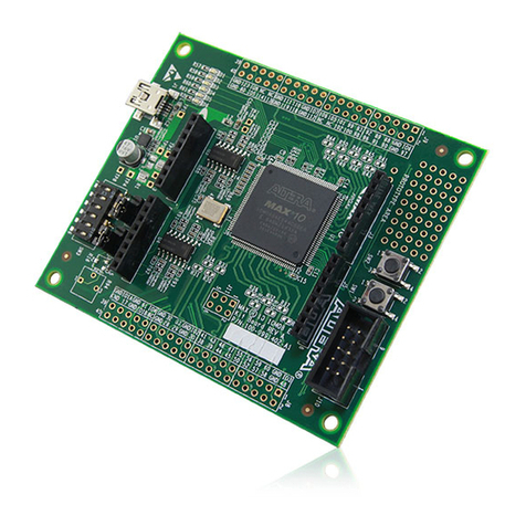
D-ULPSM Rev 0.3 (available individually or as part of DSDK).
One or more SPEC Sensors (in pinned package).
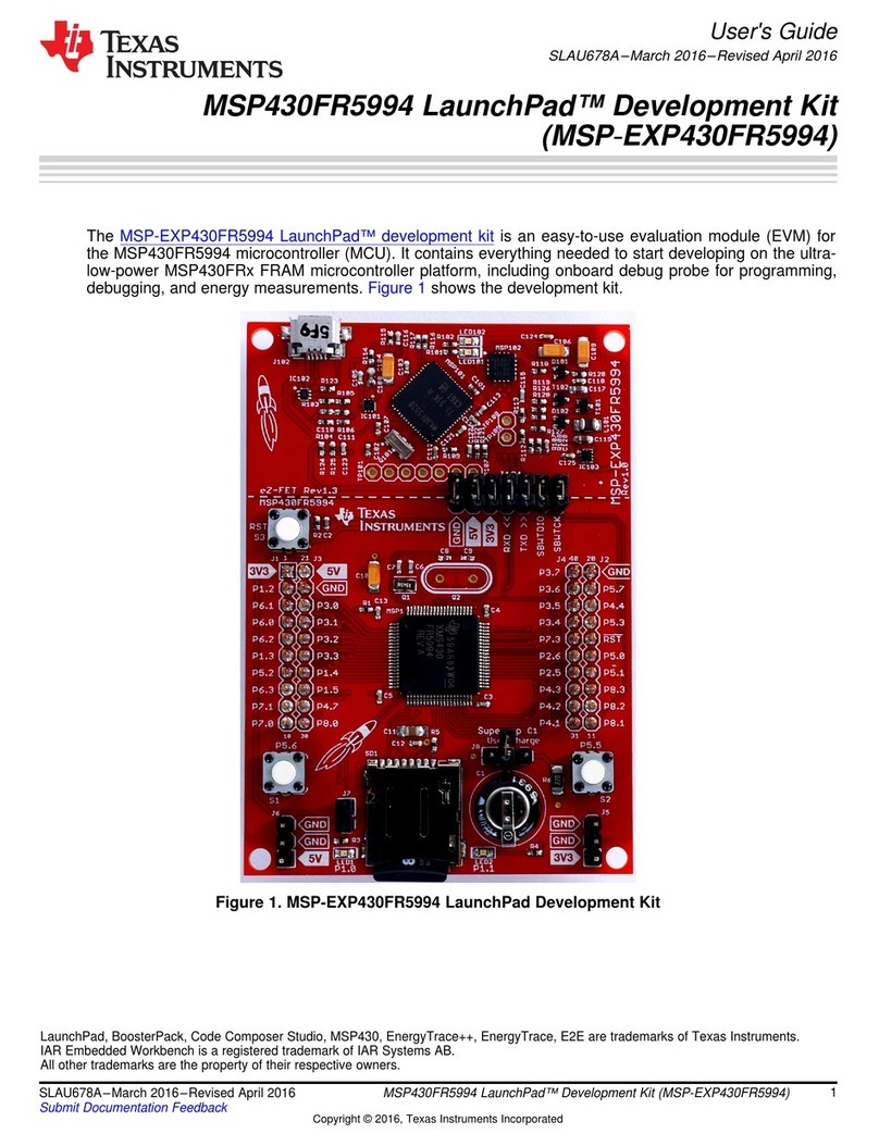
USB-to-UART Module with Pinout Adapter Board (included with purchase of D-ULPSM or DSDK).
2. Required 3rd-Party Hardware
Computer with USB port and Windows XP or later.
3. Instructions
3.1. Getting Started
Connect D-ULPSM Rev 0.3 module to the USB-to-UART Module via the Pinout Adapter Board.
Connect the assembly to a USB port on a Windows PC.
Locate and open the Device Manager.
Expand the Ports (COM & LPT) heading.
oIf the USB-to-UART Module mounted properly, you will see Silicon Labs CP210x USB to UART
Bridge (COMXX), where XX is replaced by the number of the associated COM port.
oIf it did not mount properly: locate, download and install “CP210x USB to UART Bridge VCP
Drivers” from the internet.
Open the SPEC DSDK Tool.

SPEC Sensors DSDK Tool 2
www.spec-sensors.com Quick Start Guide, Rev. 0.1
(510) 574-8300
3.2. Setup
Under the Setup tab, type the COM port number in the
COM Port field
Press Open COM Port
3.3. Configure the D-ULPSM for a Different Gas Sensor
The DSDK ships from SPEC Sensors pre-configured for the
CO sensor. To configure the module for another sensor,
follow the instructions below. Otherwise, skip to Section 3.4.
Always remove the gas sensors from the module
before reconfiguring the module.
Use a barcode scanner or smartphone app to read and
decipher the 2D barcode on the back of the sensor.
oThe sensor barcode includes the following information: Unique sensor serial number, sensor part
number, target gas, date code, and sensitivity code. For more information, refer to SPEC Sensors
document 590-002.
If necessary, transcribe the deciphered code into the barcode field to the right of the button. Double-check
for accuracy. Then press Set Barcode.
The module will take up to 1 minute to reconfigure the settings and calculate parameters.
Wait until the module returns: “Set OC….done”, then
plug the sensor into the module and allow the sensor to
stabilize. The stabilization time may vary among
sensors, depending on the target gas, bias settings,
gain settings, and history of use.
3.4. Read Gas Sensor Measurements
Under the Read tab, press the Single Read PPB
button.
oThe ppb gas measurement will display in the
field next to the button
oThe full serial string will appear in the field at
the bottom of the window
oThe format of the full serial string is:
032116030233, 0, 24, 37, 32697, 26604, 22706, 00, 02, 06, 46
1
2
3
4
5
6
7
8
9
10
11
032116030233
0
24
37
32697
26604
22706
00
02
06
46
1 Unique Sensor Serial Number
2 Gas Concentration (ppb)
3 Temperature (°C)
4 Relative Humidity (%)
5 Gas Sensor Measurement (ADC counts)
6 Temperature Sensor Measurement (ADC counts)
7 Relative Humidity Sensor Measurement (ADC counts)
8 Timer, Days on power (up to 31 days)
9 Timer, Hours on power (up to 23 hours)
10 Timer, Minutes on power (up to 59 minutes)
11 Timer, Seconds on power (up to 59 seconds)
To start logging consecutive measurements to a file, press the Start/Stop Logging button.
oApproximately once per second, consecutive measurements will be displayed in the field at the
bottom of the window.
oThe measurements will also be saved under a default file name in the default file location, indicated
below the buttons.
oIf the default file already exists, additional data will be appended to the end of the file.

SPEC Sensors DSDK Tool 3
www.spec-sensors.com Quick Start Guide, Rev. 0.1
(510) 574-8300
To stop logging, press the Start/Stop Logging button again.
To read the contents of the EEPROM memory,
oIf necessary, stop logging.
oPress the Read EEPROM button.
oA single ppb gas measurement will display at the bottom of the window, followed by a read-out of
the EEPROM memory variables.
3.5. Advanced Settings
The sensor calibration may be modified by changing
both the zero value and the span value. For best
results, re-calibration should be done near room
temperature (20 °C, 50% RH).
oTo change the zero, ensure there is no target
gas present. Press the Re-Zero button. The
module will take up to a minute to calculate a
new zero.
oTo change the span, place the module in an
enclosed environment and safely expose it to
a known concentration of the target gas. Allow
the environment and module to stabilize at the
concentration. Type the known concentration
(in PPM) into the field next to the Re-Span button, then press the button. The module will take up to
two minutes to calculate a new span factor.
oTo reset the calibration, remove the sensor from the module and follow the instructions to
Configure the D-ULPSM for a Different Gas Sensor.
An offset may be added to the temperature sensor. Type the desired offset into the field to the right of the
button and then press Set Temperature Offset.
WARNING: Using the Set 3 LMP bytes button should be done with CAUTION. Changing these settings may
severely alter the operation of the sensor. Furthermore, it may temporarily or permanently damage the
sensor.
When the D-ULPSM module is reconfigured based on the sensor barcode, the potentiostat control circuit
settings are set to defaults that were determined to be optimal by SPEC Sensors. To change the settings
manually, first refer to the Texas Instruments LMP91000 data sheet for more information on the operation of
the chip and the available settings options.
In the SPEC Sensors DSDK Tool, there are 3 fields to the right of the Set 3 LMP bytes button. From left to
right, they correspond to: TIACN (TIA Control Register), REFCN (Reference Control Register), and
MODECN (Mode Control Register). Determine the desired binary word settings for each register, convert to
decimal, enter those decimal values into the 3 corresponding fields, and then press the button.
Table of contents