Specified Technologies EZ-PATH MAX EZD44 Assembly instructions

ASSEMBLING A PATHWAY GROUP
Adouble hook and eye attachment is provided to secure pathways into a single group. Optional accessories including EZP544W Multi-Gang Wall
Brackets may be used to support a pathway group (sold separately).
1. Align devices on a solid, flat surface and insert hook into eye window. Press down firmly to connect devices. (See Fig. 3)
2. Connect one to five devices together dependent upon project requirements.
3. Insertganged devices through wall opening (with the stamping) and center within the wall assembly.
COVERING HOOK & EYE WINDOWATTACHMENT OPENINGS
NOTE: UL Classified Systems require unused attachment hook and eye windows to be covered to attain published
air/smoke leakage ratings. Orange stickers are provided for sealing these openings on the right and left side of
single installed pathways and on the end units of pathway groups. (See Fig. 4)
When casting or grouting pathway, in accordance with appropriate UL design, cover hook & eye window attachment
openings and exercise carenot to restrict the travel of retainer plates.
INSTALLING THE PATHWAY USING WALL PLATES
Pathway is installed through wall and attached using wall plates to sandwich the wall. No mechanical attachment to the wall
itself is required; however,predrilled holes are provided for optional attachment if desired.
1. Pre-install required set screws in wall plates.
2. Install a wall plate around pathway making sure that set screw flanges are facing towards the end of the device.
(NOTE: Position plate so that the stamping on the plate aligns with the lid of the raceway. Use gauge marks
located on lid of pathway to adjust plate to thickness of wall (See Fig. 5). This will center the pathway within the
wall. When properly adjusted, tighten set screws to lock plate onto pathway.
This device may be installed through either rectangular or round openings.
Gypsum Board Walls (Rectangular Openings)
1. Locate suitable area of the wall to penetrate making sure that there are no
studs, wires, pipes, or other obstructions located within the wall.
2. Mark a rectangular opening nominally 4-5/8” (118 mm) high by 4-1/8” (105
mm) wide. Make sureopening is squareand plumb. The inside of the wall
plates may be used as a template (See Fig. 1).
3. Using a keyhole saw,cut gypsum wallboard(See Fig. 2). Cutting to the outside
of the line will produce a slightly oversized opening. Mark and cut opposite
side of the wall, exercising careto align both openings. Insertpathway and
check for fit. Remove pathway.
4. Install pathway per instructions below.
Page 1 of 2 Installation Sheet •EZPATH® MAX FIRE RATED PATHWAY • ZIS1018 01/2006
GENERAL INSTRUCTIONS
CATALOG NUMBER EZD44, EZDP44
GENERAL – READ COMPLETELY BEFORE INSTALLING
EZPATH®MAX can be installed in a variety of different applications through the use of different accessories. This sheet provides installation information
for wall applications. The pathway (device) consists of a heavy gauge galvanized steel channel with detachable lid. Other accessories such as multi-
gang wall brackets, floor plates, or multi-gang floor brackets must be ordered separately and are covered under separate installation sheets.
CREATING THE OPENING
Fig. 1 Fig. 2
Gypsum BoardWalls (Round Openings)
As an alternate to the rectangular opening, using a hole saw, cut a 6” (152 mm) diame-
ter opening in both sides of the wall.
Concrete or Masonry Walls (Round or Rectangular Openings)
Cut or form a rectangular opening nominally 4-5/8” (118 mm) high by 4-1/8” (105
mm) wide or core drill a 6” (152 mm) diameter round opening.
( INSTALLING THE PATHWAY USING WALL PLATES - CONTINUED ON SIDE 2)
INSTALLATION
SHEET
Fig. 4
Fig. 3
Fig. 5
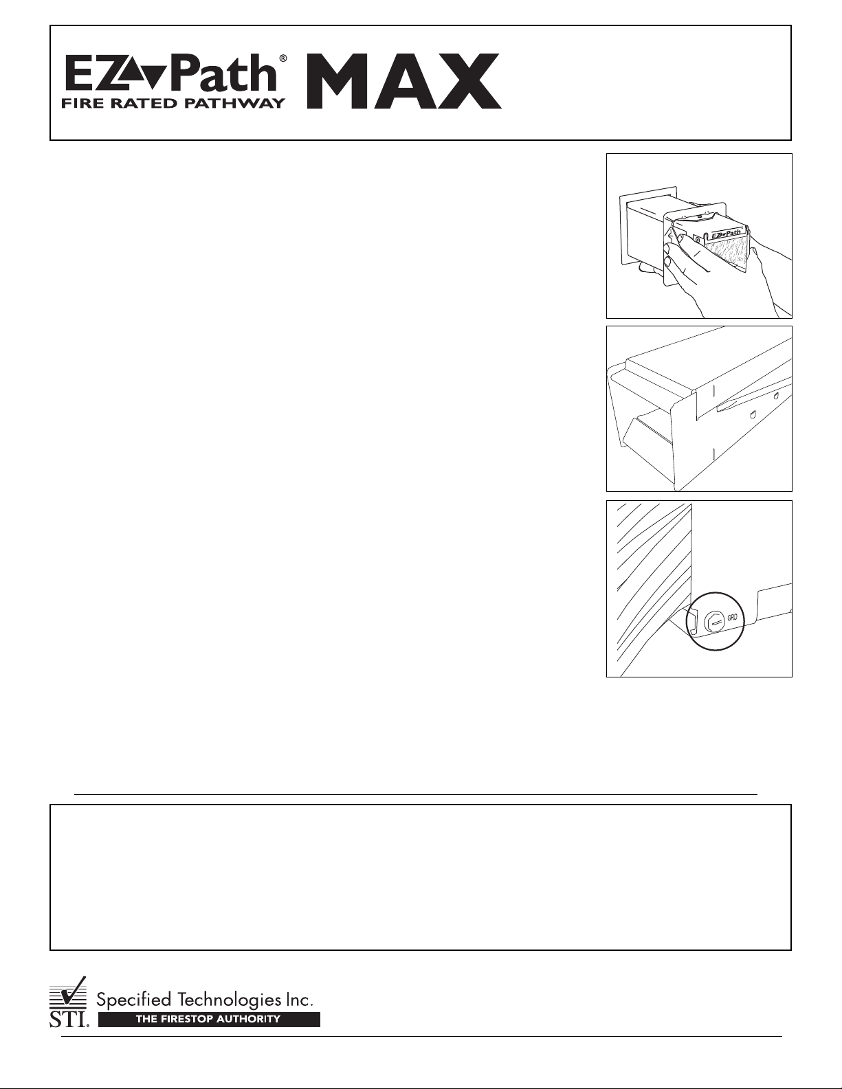
3. Place one of two provided intumescent gaskets around opposite end of pathway and carefully slide it back
to fit snugly against back side (wall side) of plate.
4. Insert pathway through wall (with the stamping) using previously installed wall plate and gasket as a stop
(See Fig. 6).
5. Moving to the opposite side of the wall, install remaining gasket around pathway and slide toward wall.
6. Install remaining wall plate around pathway (the stamping up) and slide it toward wall surface. While pulling
pathway toward you, push wall plate and gasket tightly to wall and tighten set screws. Check pathway
for excessive play. If pathway appears to be loose or can easily be moved, readjust wall plates as
necessary to tighten pathway firmly against wall.
REMOVING LID TO FACILITATE INSTALLATION AROUND EXISTING CABLES
Pathway lid is removed to allow device to be installed around existing cable bundles. Use Catalog Number
EZDP544W or EZDF144 and follow instructions provided with product to ensure compliant installation.
1. Insert flat head screwdriver into seam between lid and channel. (See Fig. 7)
2. Gently pry the lid upwards moving laterally along pathway device. Repeat step on opposite side until
the lid is removed.
3. Place pathway channel around cables.
4. Replace lid and exert pressure down to snap it in place.
INSTALLING OR PULLING CABLES
Aresilient liner and spring-loaded plates provides an adjustable seal within the pathway. Liner must be pro-
tected from damage while adding or removing cables. Wrap cable ends with a suitable low friction tape before
inserting into the raceway. This pathway is designed to be fully functional at all cable loadings from completely
empty to visually filled and cables should easily slide through the pathway using minimal effort. IF RESIS-
TANCE IS ENCOUNTERED, DO NOT FORCE CABLES OR CABLE BUNDLES THROUGH THE PATHWAY. DAMAGE
MAY RESULT. Upper curved liner may be depressed if necessary when inserting cables using a flat, smooth
implement and removing after cables are installed.
GROUNDING
At the option of the installer,this pathway may be grounded. After pathway has been installed, insertground
screws where indicated (See Fig. 8).
WALL LABELING
Wall labels are provided with the pathway as well as wall plate kits. Larger orange colored label is intended to
be used to identify the pathway installer as well as to provide applicable UL System information. Smaller sec-
ondarylabels areincluded with multi-gang wall brackets as an optional method for identifying or marking cable
Important Notice: All statements, technical information, and recommendations contained herein are based upon testing believed to be reliable, but the accuracy and completeness thereof is not guaranteed.
WARRANTY: Specified Technologies Inc. manufactures its goods in a manner to be free of defects. Should any defect occur in its goods (within one year), Specified Technologies Inc., upon prompt notification, will at its option, exchange
or repair the goods or refund the purchase price.
Limitations and Exclusions: THIS WARRANTY IS IN LIEU OF ALLOTHER REPRESENTATIONS EXPRESSED OR IMPLIED (INCLUDING THE IMPLIED WARRANTIES OF MERCHANTABILITY OR FITNESS FOR USE) AND UNDER
NO CIRCUMSTANCES SHALL SPECIFIEDTECHNOLOGIES INC. BE RESPONSIBLE FOR ANY INCIDENTAL OR CONSEQUENTIALPROPERTY DAMAGE OR LOSSES. PRIOR TO USE,THE USER SHALL DETERMINE THE SUIT-
ABILITY OF THE PRODUCTFOR ITS INTENDED USE, AND THE USERASSUMES ALLRISKS AND LIABILITY FOR SUBSEQUENTUSE. No statement or recommendation not contained herein shall have any force or effect unless in
an agreement signed by officers of seller and manufacturer.
MADE IN THE USA – COPYRIGHT © 2006 SPECIFIED TECHNOLOGIES, INC.
Page 2 of 2 Installation Sheet •EZPATH® MAX FIRE RATED PATHWAY • ZIS1018 01/2006
INSTALLATION
SHEET
Fig. 6
Fig. 8
Fig. 7
types, uses, or trades. Two sets of labels are provided for marking both sides of wall.
MAINTENANCE
No maintenance of the pathway is normally required. Interior of pathway should be inspected before and after any modifications to cable bundle. If
any damage to intumescent pads lining top and bottom of the pathway is found, contact the factory to determine if replacement is necessary.
This manual suits for next models
1
Table of contents


