1. Using the clamping ring (part #3) as a template, drill holes
in the pool wall for installation. The center line of the clamping
ring should be 12” BELOW the water level (See Figures 14 &
15). Two additional holes will need to be drilled at the 3 and
9 o’clock positions for installation of the jet housing (part #7).
The four brass inserts in the clamping ring should be at the 2,
4, 8 and 10 o’clock positions (See Figure 14).
2. Mount the housing (part #7) and one clamping ring gasket
(part #12) on BEHIND the pool wall using two (2) #14 x 1”
counter sunk screws (part #27). Install the screws from the
inside of the pool wall through the holes drilled at 3 and 9
o’clock positions. (See Figure 14)
3. Install the clamping ring (part #3) and a second clamping
ring gasket (part #12) in FRONT of the pool wall using eight
(8) M6 screws (part # 9/2, 9/3, or 9/4). Screw lengths vary
depending on the installation. NOTE: A good RTV silicone may
be used with the gasket when mounting the jet housing, but in
most cases is not necessary. Installer should decided whether
or not the silicone is necessary.
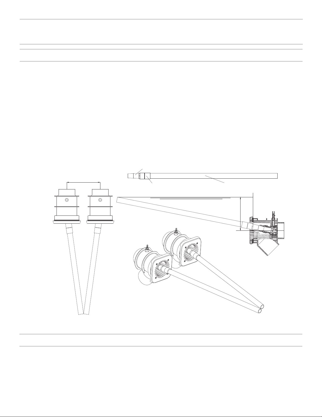
NOTE: When installed properly, the center of the housing (part
#7) will be 12” BELOW the surface of the water and the air
regulator hose nipple (part #14) will be at the top center of
the jet housing.
CAUTION: When installing the BaduStream Cover (part #8).
Use a Phillips head screw driver and tighten to 1.5 Nm or hand
tight. DO NOT use electrical or air drills. (NOTE: The square
cover, part #8, will have an uneven appearance if the housing
is not installed properly.)
4. For the air regulator assembly, one 1/2” hole must be
provided, preferably along the vertical axis, approximately
3-4” ABOVE the water line. (See Figures 14 & 15). Using the
60 x 11 x 2mm air regulator gasket (part #21), mark and drill
two 1/4” mounting holes (See Figure 14). Use the two (2) 1/4 -
20 air holder screws (part #18) and two 1/4-20 air holder nuts
(part #19) to mount the air regulator holder.
NOTE: Part #18 & Part #21 go in FRONT of the pool wall; Part
#19 & Part #17 go BEHIND the pool wall.
5. Keep all parts not being used now in original box. Store in a
safe place until needed.
6. Once the pool is complete, install the square cover (part #8)
using the four (4) square cover screws (part #9/1).
For Liner Pools Only: Install the jet housing and air regulator
prior to installation or replacement of the pool liner.
For Steel Walled Pools: An optional butterfly gasket (part
#12.1) maybe purchased to replace the two (2)clamping ring
gaskets (part #12). Increase the jet housing hole in Figure 14
from 5.59” to 5.75” for installation.
12”
Housing
Discharge
Deck
Air Regulator
Air Line
3”
Minimum Water Level
Suction
Liner &
Wall
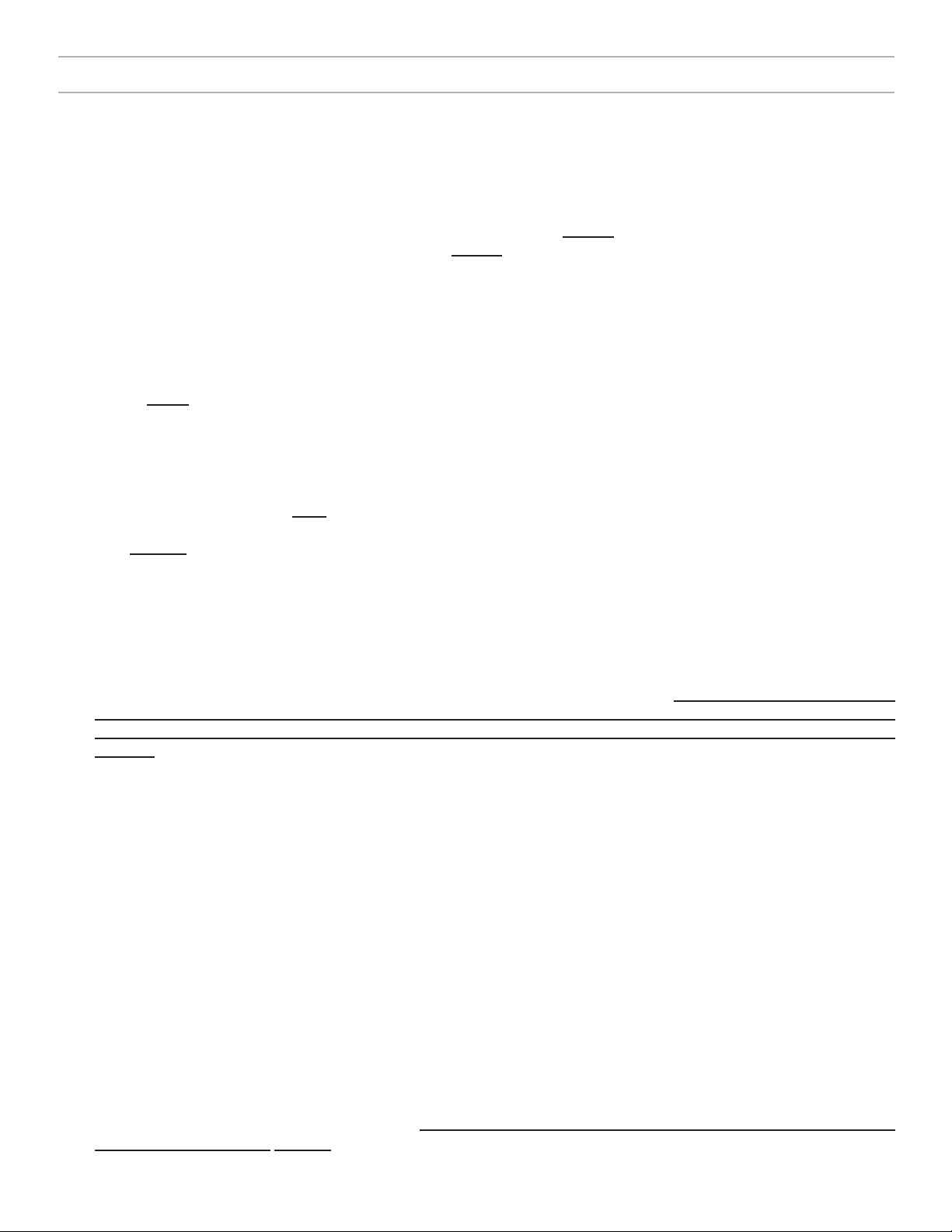
Fitting 4”
Pipe
Fitting 4”
45oElbow
Water Level
0.5” 1.70”
0.25”
12”
3”
Minimum
0.3”
25o
6.54” dia
5.59” dia
For Liner & Fiberglass Pools Only
(Jet House Mounting Holes)
14
Liner and/or Fiberglass Pool Installation
Figure 14
Figure 15
Cutout Pool Wall for BaduStream housing.
BaduStream in Liner or Fiberglass Pool.