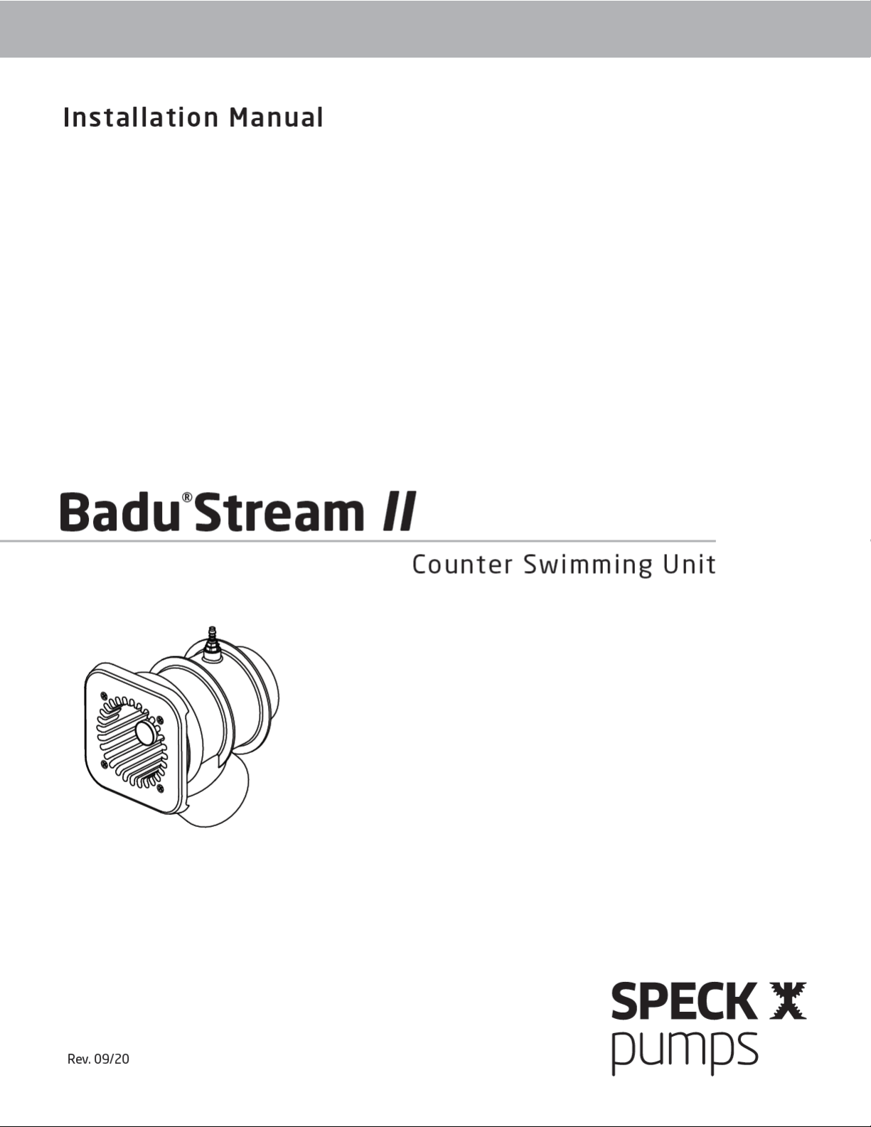
Speck pumps Badu Stream II User manual

2999999189 - Rev. 0920 - SW FA.300.JP
Technical Support:
Address: Speck Pumps
8125 Bayberry Road
Jacksonville, FL. 32256
USA
Hours: (Monday - Friday) 8:00 am to 5:00 pm EST
Toll Free: 800-223-8538
Phone: 904-739-2626
Fax: 904-737-5261
Website: www.usa.speck-pumps.com
Manufactured by Speck Pumps, Jacksonville Florida USA, ©2021 All Rights Reserved.
This document is subject to change without notice.
Date of Installation:
Installed by:
Serial Number:
For Service Call:


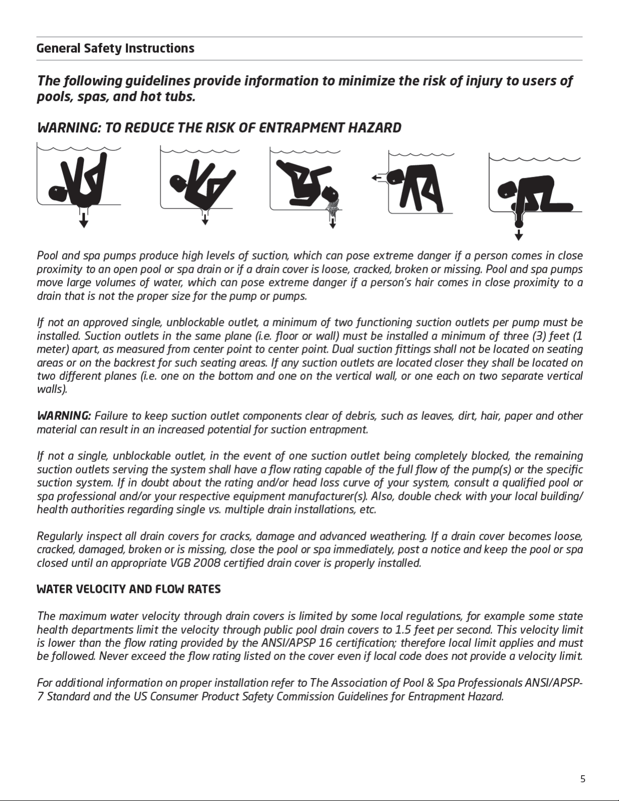
Swim Jet Combination Fitting - Manufacturers Warnings
4
WARNING: Before Installing this product, read and follow all warning notices and instructions which are included.
Failure to follow safety warnings and instructions can result in severe injury, death, or property damage. Call
(800) 223-8538 or visit www.usa.speck-pumps.com for additional copies of these instructions.
1 Important Safety Instructions
MUST BE INSTALLED by an experienced and qualified pool industry professional ONLY.
Attention Installer: This manual contains important information about installation, operation, and safe use of
this product. This information should be given to the owner and/or operator of this equipment. Most states and
local codes regulate the construction, installation and operation of pools and spas. It is important to comply with
these codes, many which regulate the installation and use of this product.
1. DO NOT locate this fitting in seating areas or on the back rests for such seating areas.
2. This fitting should be mounted in the vertical pool wall only per manufacturer’s instructions.
3. All fittings and fasteners should be examined for damage or tampering before each use.
4. Any missing, broken, or cracked fittings must be replaced before using this product. Only genuine Speck
replacement parts may be used.
5. Acceptable fittings/pipe sizes are listed on page 8 of this manual. No other sizes are permitted.
6. Never exceed the maximum flow rate stated on this product.
7. The anti-entrapment cover must be in place when using this product. DO NOT use this product if the cover is
missing, broken, or loose.
8. The anti-entrapment cover (part# 8) should be replaced within 10 years from installation date.
9. Installation requires a Phillips screw driver. Hand tighten only. DO NOT use electrical or air drills.
10. Consult your physician before exercising with the Badu®Stream II or using the massage hose.
11. DO NOT permit children to use this product unless they are closely supervised at all times.
12. DO NOT remove any safety alert labels such as DANGER, WARNING, or CAUTION. Keep safety alert labels
in good condition and replace missing or damaged labels.
13. Stay alert, watch what you are doing and use common sense. DO NOT use unit if you are tired and/or ex-
hausted. DO NOT use unit while under the influence of drugs, alcohol, or any medications.
CAUTION: DO NOT increase pump size; this will increase the flow rate through the system and exceed the
maximum flow rate stated on this product.
IMPROPER INSTALLATION OR USE OF THIS PRODUCT MAY PRESENT A RISK OF HAIR OR BODY ENTRAPMENT
AND DROWNING. Install this equipment in accordance with the instructions provided.
As the manufacturer, Speck Pumps-Pool Products, Inc., hereby certifies that their Swim Jet Combination Fitting
meets or exceeds the requirements of the Virginia Graeme Baker Pool & Spa Safety Act, VGB 2008 and ANSI/
APSP 16-2011 standards and safety regulations as set forth by the Consumer Products Safety Commission.
“Read, and then keep these instructions for future reference”

7
2 General Description
Receiving Information
The Badu SwimJet Systems from Speck Pumps are designed to be installed during the construction of your pool to create a
water treadmill for anyone wanting a therapeutic and eective exercise.
The Badu SwimJet Systems can be installed in any type of pool, large or small, from gunite to vinyl liner. It has no protruding
parts ensuring pool user’s safety, is very compact and installs at minimal cost. The self-contained, flush-mounted unit is a
jet-propulsion system that pumps water into the pool creating a current in excess of 5,700 gallons per minute from a single
recessed jet housing.
Topping o the experience is the pulsating massage hose which can be attached to the jet nozzles for easy and convenient
massage treatments for joints and muscles. (NOTE: The massage hose is sold separately.)
Badu®Stream II
3 Installation Information
1. Upon receipt of the swimjet system, check the cartons for damage. Open each carton and check the pump(s), jet housing(s),
and control box for concealed damage, such as cracks, dents, or a bent base. If damage is found, contact the shipper or
distributor where the swimjet was purchased.
2. Inspect the contents of each carton and verify that all parts are included. (See Image 1)
A
DF
B
E
C
G
Image 1
BaduStream II System (1 jet & 4 HP pump)
Flush-mount jet housing
Square, anti-entrapment cover (81/4” x 81/4”)
undetectable pump suction. (Optional Round
Cover available)
Adjustable water flow jet nozzle
Air regulator adjusts amount of air bubbles in
water flow.
Control box complete with GFCI and WiFi
control module.
SPECK Model 21-80/33GS 4.0 HP (or a SPECK
Model 72-VI 3.5 HP) self-priming, single
phase plastic pump with built-in thermal
overload (no motor starter required). Optional
three phase pump and control box available.
(NOTE: Flooded suction pump available for
installation below water level.)
System (ON/OFF) LED Touch Button - Complete with 1.5” threaded housing fits into any 1.5” return fitting. The
Touch button turns the swimjet system ON/OFF. Waterproof button may be installed below water level.
A.
B.
C.
D.
E.
F.
G.

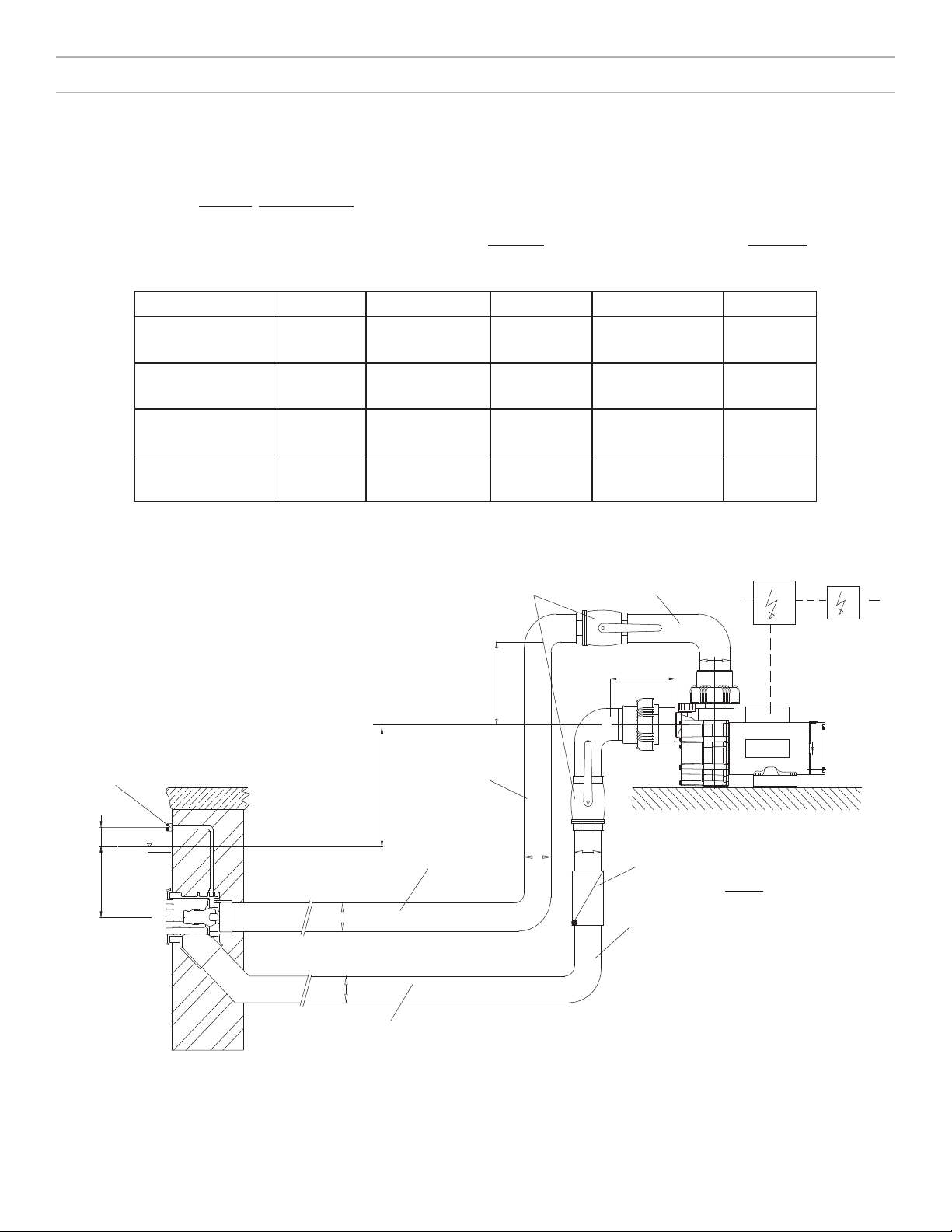
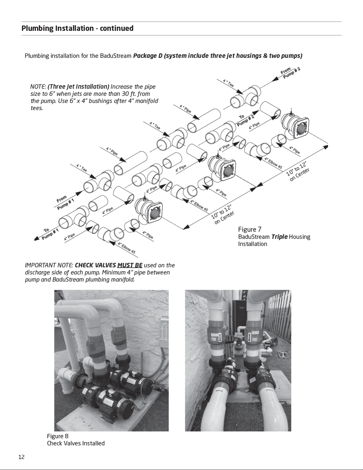
Plumbing Installation
8
For optimal performance, use 4” plumbing when the total distance between the pump and jet housing is 30 ft or less.
The plumbing should be as direct and free from turns or bends as possible because elbows and other fittings can
create large friction losses and reduce the performance of the system. The shortest length of pipe with the
minimum number of fittings possible should be used to avoid any significant friction loss due to the pipe and
fittings. NOTE: Refer to Figure 2 for the BaduStream head loss curve.
A maximum of seven (7) 90oelbows may be used with 30 ft of horizontal 4” pipe for the suction line and 30 ft of
horizontal pipe for the discharge line without negatively aecting the performance of the system.
NOTE: This applies to each individual pump used on the system. Refer to Figure 4 for the maximum TDH allowed to
achieve recommended flow rates.
If more elbows are required for the installation, 4” sweeps must be used in place of the elbows. When using sweeps
instead of elbows, a maximum of nine (9) 4” sweeps may be used with 30 ft of horizontal 4” pipe for the suction line
and 30 ft of horizontal 4” pipe for the discharge line without negatively aecting the performance of the system. NOTE:
This applies to each individual pump used on the system. Refer to Figure 4 for the maximum TDH allowed to achieve
recommended flow rates.
If the pump(s) cannot be located within 30 ft of the jet housing(s) using the maximum number of 4” elbows or sweeps
stated above, then 6” plumbing must be used. For the suction line, use 6” plumbing and fittings from the connection
at the jet housing (or at the manifolds for two and three jet systems) to a point directly beneath the pump. From that
point, install a 6” elbow. Then run 4” pipe vertically up to the suction connection of the pump and finish with a 4” elbow.
For the discharge line, 6” plumbing should be installed from the discharge connection of the pump all the way to the
pressure connection of the jet housing (or manifolds for two and three jet systems).
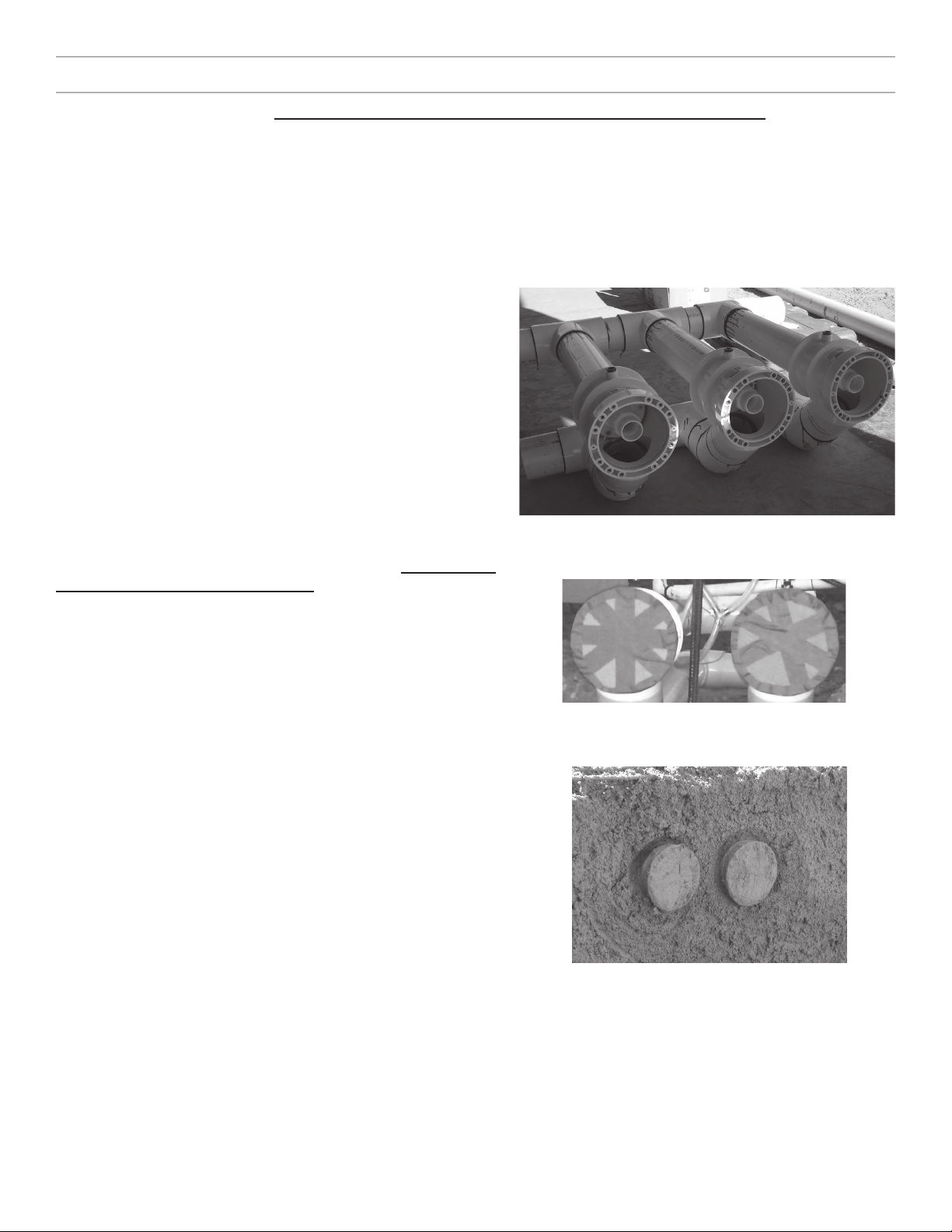
For two and three jet systems, the jet housings must be installed as close to 10” center to center as possible for
maximum performance. DO NOT install the jet housing more than 12” apart on center. (See Figure 1 & 1A)
n
n
n
n
n
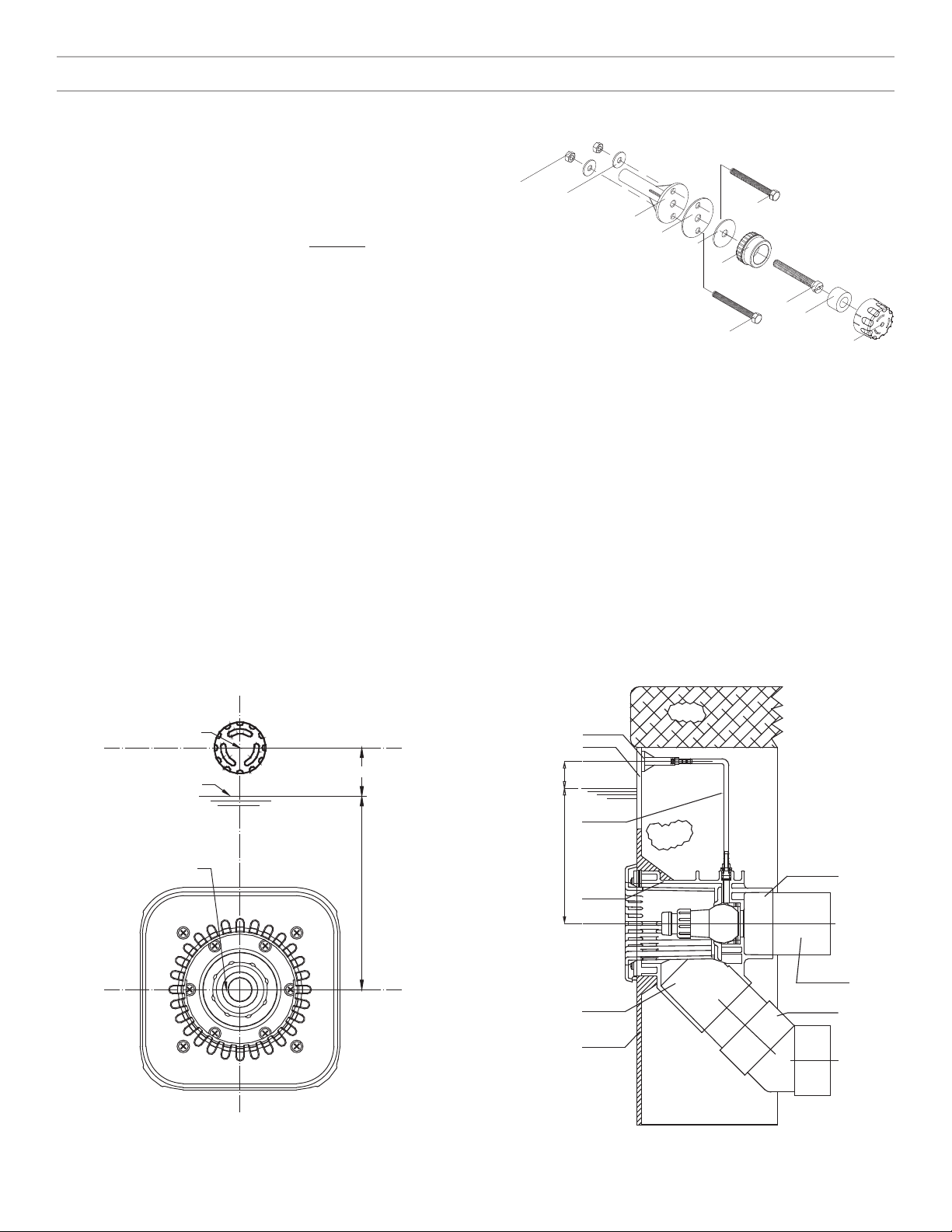
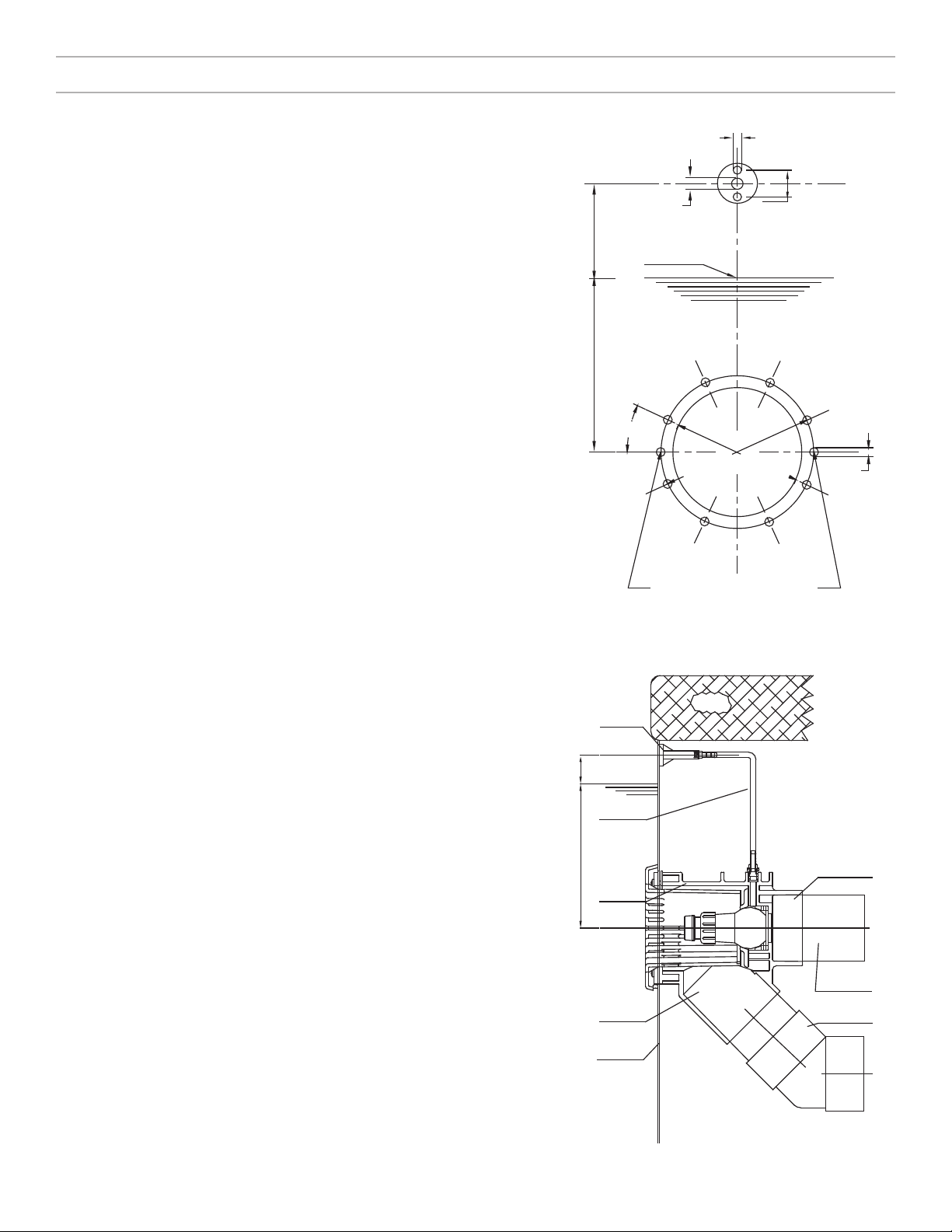
CAUTION: The discharge connection is at the center of the back of the jet housing. The suction connection is at the bottom
of the jet housing.
CAUTION: The suction line should remain below water level from the suction connection at the jet housing to a point directly
beneath the pump.
CAUTION: The center of the BaduStream jet nozzle(s) must be located 12” BELOW the water line for maximum performance
and eciency. The air regulator(s) should be located 3-4” ABOVE the water line.
CAUTION: In areas with soft soil conditions or with frequent earth movement, a flexible section of 4” hose should be
installed at the back of the jet housing to prevent plumbing or jet housing damage.
CAUTION: For trouble-free pump priming (up to 4 feet above the water line), first install a 6” long riser in the discharge
connection on top of the pump(s). Then install an elbow and lead the discharge line(s) downward to the discharge connection(s)
at the BaduStream jet housing(s) (Not required with 3.5 HP pump Model 72). On systems with 3 jet housings and 2 pumps,
check valves MUST be installed at the discharge connections at each pump.
CAUTION: Allow at least 12 hours curing and bonding time. Insucient curing and bonding times can result in leaks and
flooding.
CAUTION: Throughout the entire installation, make sure the plumbing connected to the BaduStream jet housing is well
supported. Unsupported plumbing WILL crack the jet housing.
CAUTION: DO NOT use the pump as a fixed point (support) for the plumbing.
CAUTION: When using 6” pipe, install 6” x 4” reducer bushings as close to the jet housing(s) as possible. For systems with 2
or 3 jet housings, install the 6” x 4” reducer bushings as close to the 4” manifold tees as possible. The 6” suction line should
be run from the jet housing(s) and remain under the water line to a point directly beneath the pump. Install a 6” elbow at
that point. Then run 4” pipe vertically up to the suction connection of the pump and finish with a 4” elbow.

0
U.S. Gallons per Minute
60
20
40
10
30
50
Total Head in Feet
180 200 220 240 260 280 300
~
70
9.25”
3.25”
0.79”
1.97”
1.97”
4.49”
4.92”
8.27”
7.32”
6.54”
5.59”
4.72”
4.49”
4.92”
Plumbing Installation - continued
9
Higher resistance which results in less ecient priming and a higher
risk of cavitation.
Longer priming time (up to 12 min).
Keep the suction and pressure lines as short and straight as possible.
If the pump is positioned further away, then the pipe dimensioning
has to be adapted so that almost loss-free flowing is ensured.
BaduStream II Head Loss Curve (Single Jet Housing)
Figure 2 Figure 3
BaduStream dimensional drawing
NOTE: Suction lines which are too long have significant disadvantages:
n
10” - 12” from center to center
10” - 12” from center to center 10” - 12” from center to center
Two Jet (10” - 12” from center to center)
Figure 1
Three Jet (10” - 12” from center to center)
Figure 1A
n
n
n
Air Regulator
Discharge Line
Vertical
Check Valve
Vertical Suction Line
6 " Riser
Control Box
Valves (Optional)
Discharge Line
Horizontal Suction Line
4"
4"
4"
4"
4"
3"
Minimum
Horizontal
12"
Maximun 4 Feet
Allow 12" to prevent
cavitation of the pump
Disconnect
Service
Water Level
Pump
Pressure Line
max. 30 feet with 4 " pipe
(Check Valve(s) are required if the pump is
more than 4 ft. ABOVE the Water Level)
Plumbing Installation - continued
10
* 6” pipe will allow distances of well over 50 ft. There is
50ft of cable included with the touch button. If a longer
distance to the control box is required, a junction box
can be installed above the water line to splice additional
cable as required.
Figure 4 NOTE: Valves are recommended when pump is installed below water level
(flooded suction applications).
NOTE: To avoid stress on the jet housing, the jet housing and 2 to 3 inches of
plumbing stub out may be encased in gunite or concrete.
NOTE: The BaduSteam assembly package contains all necessary parts for the installation of the unit into concrete, gunite,
liner or fiberglass pools.
CAUTION: All necessary screws and bolts included with the BaduStream are stainless steel. ALL screw threads and
threaded inserts are METRIC! ONLY METRIC bolts and nuts may be used! The two exceptions are the suction and discharge
connections on the BaduStream and pump housing (4” slip connections) and the mounting hardware for the air regulator
assembly (1/4 -20 threads). All screws should be HAND TIGHT. DO NOT use drills or pneumatic tools. DO NOT over tighten!
Plumbing Requirements
BaduStream II Pump Distance Pipe Size Approx. Flow TDH
Three Jets (2) 4 HP 10 to 30 ft.
up to 50 ft.*
4”
6”
651 GPM
651 GPM
42 ft
42 ft
Two Jets 4 HP 10 to 30 ft.
up to 50 ft.*
4”
6”
380 GPM
400 GPM
34 ft
32 ft
One Jet 4 HP 10 to 30 ft.
up to 50 ft.*
4”
6”
217 GPM
217 GPM
53 ft
53 ft
One Jet 3 HP 10 to 30 ft.
up to 50 ft.*
4”
6”
200 GPM
200 GPM
12 ft
12 ft

13
1. Pre-plumb BaduStream jet housing(s):
4. Install the air regulator. NOTE: Air regulator location should be 3”- 4” ABOVE the water level.
Figure 11
V-Shaped Groove in Gunite
Install plumbing manifold (for two and three jet systems) or
approximately 12” of 4” SCH 40 pipe (for single jet systems)
to both suction and discharge fittings on the jet housing(s).
See Figure 9
Thread one (1) air regulator hose nipple into the top of each
jet housing. Secure plastic air regulator hose (part #15) to
the air regulator hose nipple(s) (part #14) using the hose
clamp(s) (part #16).
A.
B.
2. Tape the jet housing(s) to keep concrete out of threaded inserts
and out of the inside of the housing(s). See Figure 10.
3. Place the jet housing(s) between the steel rebar. Note: The jet
housing location is very important.
A.
B.
C.
D.
E.
Figure 9
Pre-Plumbed Jet Housings
Figure 10
Taped Jet Housings
NOTE: The following parts ARE NOT USED IN A GUNITE or CONCRETE INSTALLATION:
Clamping Ring Gasket (Part #12)
1/4-20 x 1-1/2” Bolt (Part #18)
1/4-20 Nut (Part # 19)
1/4” Washer (Part #20)
Air Regulator Gasket 60 x 11 x 2 mm (Part #21)
#14 x 1” Screw (Part #27)
n
n
n
n
n
n
Make sure that the air regulator hose nipple (part #14) is
at the top and center of each jet housing. Failure to do
so will result in the square cover (part #8) appearing
uneven.
The center of each jet housing (the nozzle) must be located
12” BELOW the water line for maximum performance and
eciency.
Recheck the location of the jet housing while applying
gunite or pouring concrete. Make sure the jet housing
remains properly aligned and level.
Front edge of each jet housing should finish even with
inside pool wall. Scrape out a V-shaped groove around the
jet housing, approximately 1.5” deep to allow marcite to
seal against the jet housing. See Figure 11.
To avoid stress on the housing, the jet housing and 2 to 3
inches of plumbing stub out may be encased in gunite or
concrete. Caution: Too much stress on the plumbing may
crack the BaduStream II housing.
A. Thread one (1) air regulator hose nipple (part #14) into the back of the air regulator holder (part #17). Connect the
free end of the plastic air regulator hose to the nipple on the back of the air regulator holder. Secure with a hose clamp
(part #16).
Concrete or Gunite Installation
19
18
20
17
21 26
23
18 22
24 25
12”
3” Minimum
Nozzle
Water Level
Air Regulator
Housing
Discharge
Tile
Deck
12”
Concrete
Wall
Air Regulator
Air Line
3”
Minimum Water Level
Suction
Plaster
Fitting 4”
Pipe
Fitting 4”
45oElbow
14
Concrete or Gunite Installation - continued
5. Keep all parts not being used now in original box. Store in a safe place until needed.
NOTE: An extension ring and longer square cover screws (part #9/5) are available (upon request) for applications where the
housing is recessed into the pool wall.
6. Once the concrete or gunite is fully cured and pool wall is completed, install the square cover (part #8) using the four (4)
M6 x 25mm square cover screws (part #9/1).
NOTE: In tile installations, the tile thickness can be compensated for by first installing the clamping ring gasket (part #12)
and clamping ring (part #3) before installing the square cover. The clamping ring and clamping ring gasket are installed using
the eight (8) clamping ring screws (part #9/2, 9/3, or 9/4).
The air regulator can be located in the tile above the
water level or in the deck. When tiling the pool, adjust
the air regulator location so it is 3”-4” ABOVE the water
level. Place and set with hydraulic cement. The air
regulator holder (part #17) should finish flush with the
inner pool wall. Drill a 1/2” hole in the tile line even with
the center hole of the air regulator holder. Tile over the
air regulator holder. CAUTION: DO NOT plug the center
hole of the air regulator holder.
Insert the M10 x 80 mm brass screw (part #24) through
the bottom part of the air regulator (part #23), the 42
x 11 x 2 mm and the air regulator gasket (part #26).
Thread the M10 x 80 mm brass screw into the center of
the air regulator holder (part #17). Tighten with a flat
head screw driver.
B.
C.
D.
Figure 12
Air Regulator Assembly
Install the hose ring (part #25) and snap the top part of the air regulator (part #22) into place. See Figure 12 for air
regulator assembly.
Figure 13 Figure 14
Installation in Concrete or Gunite Pools BaduStream in Concrete or Gunite Pool.
1. Using the clamping ring (part #3) as a template, drill holes
in the pool wall for installation. The center line of the clamping
ring should be 12” BELOW the water level (See Figures 15 &
16). Two additional holes will need to be drilled at the 3 and
9 o’clock positions for installation of the jet housing (part #7).
The four brass inserts in the clamping ring should be at the 2,
4, 8 and 10 o’clock positions (See Figure 15).
2. Mount the housing (part #7) and one clamping ring gasket
(part #12) on BEHIND the pool wall using two (2) #14 x 1”
counter sunk screws (part #27). Install the screws from the
inside of the pool wall through the holes drilled at 3 and 9
o’clock positions. (See Figure 15)
3. Install the clamping ring (part #3) and a second clamping
ring gasket (part #12) in FRONT of the pool wall using eight
(8) M6 screws (part # 9/2, 9/3, or 9/4). Screw lengths vary
depending on the installation. NOTE: A good RTV silicone may
be used with the gasket when mounting the jet housing, but in
most cases is not necessary. Installer should decided whether
or not the silicone is necessary.
NOTE: When installed properly, the center of the housing (part
#7) will be 12” BELOW the surface of the water and the air
regulator hose nipple (part #14) will be at the top center of
the jet housing.
CAUTION: When installing the BaduStream Cover (part #8).
Use a Phillips head screw driver and tighten to 1.5 Nm or hand
tight. DO NOT use electrical or air drills. (NOTE: The square
cover, part #8, will have an uneven appearance if the housing
is not installed properly.)
4. For the air regulator assembly, one 1/2” hole must be
provided, preferably along the vertical axis, approximately
3-4” ABOVE the water line. (See Figures 15 & 16). Using the
60 x 11 x 2mm air regulator gasket (part #21), mark and drill
two 1/4” mounting holes (See Figure 15). Use the two (2) 1/4 -
20 air holder screws (part #18) and two 1/4-20 air holder nuts
(part #19) to mount the air regulator holder.
NOTE: Part #18 & Part #21 go in FRONT of the pool wall; Part
#19 & Part #17 go BEHIND the pool wall.
5. Keep all parts not being used now in original box. Store in a
safe place until needed.
6. Once the pool is complete, install the square cover (part #8)
using the four (4) square cover screws (part #9/1).
For Liner Pools Only: Install the jet housing and air regulator
prior to installation or replacement of the pool liner.
For Steel Walled Pools: An optional butterfly gasket (part
#12.1) maybe purchased to replace the two (2)clamping ring
gaskets (part #12). Increase the jet housing hole in Figure 15
from 5.59” to 5.75” for installation.
12”
Housing
Discharge
Deck
Air Regulator
Air Line
3”
Minimum Water Level
Suction
Liner &
Wall
Fitting 4”
Pipe
Fitting 4”
45oElbow
Water Level
0.5” 1.70”
0.25”
12”
3”
Minimum
0.3”
25o
6.54” dia
5.59” dia
For Liner & Fiberglass Pools Only
(Jet House Mounting Holes)
15
Liner and/or Fiberglass Pool Installation
Figure 15
Figure 16
Cutout Pool Wall for BaduStream housing.
BaduStream in Liner or Fiberglass Pool.

16
Removal of Liner
Electrical - SPECK Controller Installation
When replacing liner or removing liner for repairs; remove the four (4) screws (part #9/1) which hold the square
cover (part #8) to the jet housing. Remove all screws (part #9/2, 9/3 & 9/4) except the top two, which hold the
clamping ring (part #3) and gasket (part #12) to the jet housing. Back out the two remaining screws approximately
halfway and check for any movement of the jet housing from the wall. (NOTE: If the two counter sunk screws
(part #27) which hold the jet housing to the wall were installed, the jet housing should not move, and the two
remaining screws can be removed.) Remove one of the remaining two screws and slide the clamping ring (part
#3) to the side. Replace all the screws before removing the last screw. Remove or replace the liner. Reverse the
process to install liner.
NOTE: When replacing the clamping ring and screws: locate screw heads under liner, make a small cut on the liner
at the screw heads and push the liner over the screw head.
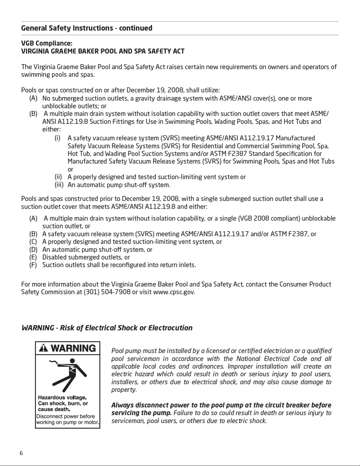
WARNING: The wiring of the pool motor and control box should be done by a licensed electrician in accordance with all
local, state, and federal codes. Be certain that the motor frame and control box are properly grounded. Motor name plate lists
voltage, phase, amp draw, and other information as well as wiring connection instructions.
This section concerns the electric motor and control box for BaduStream II swimjet system.
CAUTION: Before installing the Speck Pump, read the entire pump owner’s manual found in the pump box.
Consult local codes for minimum distance between pump and pool. Locate pump as close to the pool as practical.
CAUTION: There is 50ft of cable included with the touch button. If a longer distance to the control box is required, a junction
box can be installed above the water line to splice additional cable as required.
NOTE: The System ON/OFF LED touch button is installed in a 1-1/2” threaded housing. This housing may be installed
in any 1-1/2” return fitting, either below the water line or above the water.
BONDING: As required by National Electrical Code, the pump motor must be electrically bonded to the pool structure
(reinforced bars, etc.) by a solid copper conductor not smaller than No. 8 AWG via the external copper bonding lug on the
pump motor.
GROUNDING: Permanently ground the pump motor and control box using a conductor of appropriate size.
CAUTION: DO NOT connect to electric power supply until the unit is permanently grounded.
NOTE: Single phase control boxes equipped with GFCI are shown on pages 17-18. Other options are available. Please contact
the factory (800) 223-8538 for assistance.
Connecting the SPECK controller to a WiFi network for the FIRST TIME:
1. Before connecting the SPECK controller to the WiFi network, stand where the SPECK equipment is located and with your
mobile device in-hand assure that the signal strength to the WiFi network is good to excellent (weak signals will cause
problems).
2. Make sure the power to the SPECK Device is turned ON. There is a green indicator on the controller board to indicate power.
A small “o” will be flashing on the LED display.
3. Give the homeowner the BADUConnect app manual and allow them to finish the App setup. For more information, Call
(800) 223-8538 or visit www.baduconnect.com for additional copies of the BADUConnect App instructions.
Pump Motor: Connect to the #10 green headed ground screw provided inside the motor terminal box.
Control Box: Connect to the aluminum grounding terminal strip on the inside of the control box enclosure.
n
n
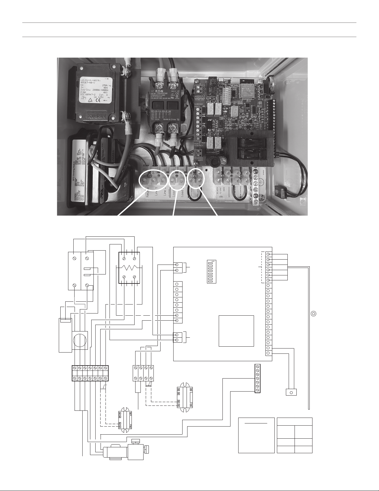
TORQUE DATA
8 CU 10
14-10 CU 7
Torque
in.-lbs.
Wire
Range
BJC RATING
1 - Circuit 28 Amps
208-240 Volts
60 Hz, 1 Phase
4-Wire Service
GFCI Protected
ON/OFF Controls
NOTE: Use TO & FROM Control for
remote operation of equipment.
Ground
Terminal
Motor
Ground
Service
Ground
WiFi Reset Button
Cable For Pump ON/OFF Button
On-Board Transformer
DIP Switches
BKRDGRBLSW1G
SW Pump 1
BLACK
RED
GREEN
BLUE
WHITE
YELLOW
Controller Power
12V Light
CONTACTOR
ON
1 2 3 4 5 6 7 8
Coil
230V
RED-5
RED-4
RED-4
RED-6
RED-2
BLK-7
BLK-2
BLK-4
BLK-5
BLK-4
ORG-0
YEL-0
ORG-0
YEL-0
BLK-2
RED-2
RED-5
BLK-6
BLK-3
RED-3
BLK-0
BLK-1
BLK-0
RED-1
WHT-1
40A Shunt
Tr p w/ AUX
Switch
C rcuit
Breaker
GFCI Module
BLK-7
BLK-1
RED-6
BLK-6
BLK-5
BLK-3
RED-3
RED-1
WHT-1
Black
Red
REMOVE JUMPER
FOR REMOTE
CONNECTION
REMOVE JUMPER
FOR REMOTE
CONNECTION
LOAD 2
From Control
LOAD 1
LINE 2
LINE 1
NEUTRAL
To Control
From Control
To Control
12VAC LED
Remote Relay
Remote Relay
Single
Speed
Motor
SERVICE
4-WIRE
1 PHASE
Terminal
Strip
43 6 752
18 9 10 11
17
Electrical - SPECK Controller Installation - Continued
Power from main panel (230 VAC):
Neutral, Line 1, Line 2
Power to pump motor (230 VAC):
Load 1, Load 2
Connection for remote relay
(Remove Jumper)
Figure 17
Control Box Wiring

TORQUE DATA
8-6 CU 10
14-10 CU 7
Torque
in.-lbs.
Wire
Range
BJC RATING
1 - Circuit 28 Amps
208-240 Volts
60 Hz, 1 Phase
4-Wire Service
GFCI Protected
ON/OFF Controls
NOTE: Use TO & FROM Control for
remote operation of equipment.
Ground
Terminal
Motor
Ground
Motor
Ground
WiFi Reset Button
Cable For Pump ON/OFF Button
On-Board
Transformer
DIP Switches
BKRDGRBLSW1G
SW Pump 1
BLACK
RED
GREEN
BLUE
WHITE
YELLOW
Controller Power
12V Light
CONTACTOR
ON
1 2 3 4 5 6 7 8
Coil
230V
RED-4
RED-8
RED-2
BLK-9
BLK-2
BLK-4
BLK-4
ORG-0
YEL-0
ORG-0
YEL-0
BLK-2
RED-2
RED-7
RED-7
RED-6
BLK-8
BLK-8
BLK-7
BLK-3
BLK-5
RED-3
RED-5
BLK-0
BLK-1
BLK-0
RED-1
WHT-1
50A Shunt
Trip w/ AUX
Switch
Circuit
Breaker
GFCI Module
BLK-3
BLK-6
BLK-5
BLK-7
RED-3
RED-5
RED-1
WHT-1
REMOVE JUMPER
FOR REMOTE
CONNECTION
LOAD 2
LOAD 3
LOAD 4
From Contro
LOAD 1
LINE 2
LINE 1
NEUTRAL
To Contro
Remote Relay
SERV CE
4-W RE
1 PHASE
Term na
Str p
43 6 7521 8 9
Service
Ground
To Motor 2
To Motor 1
BLK-1
CONTACTOR
Coil
230V
RED-4
RED-6
BLK-6
RED-8
BLK-9
18
Power from main panel (230 VAC):
Neutral, Line 1, Line 2
Power to pump motor 1
(230 VAC): Load 1, Load 2
Power to pump motor 2
(230 VAC): Load 1, Load 2
Connection to remote relay
(120 VAC)
Electrical - SPECK Controller Installation - Continued
Figure 17A
Control Box Wiring

PATTERN ON LED DISPLAY CONDITION
Flashing Dash (-) with an interval of ~200ms Ideal with no Relay/Pump on
Flashing ‘P’ with the interval of ~200ms No WiFi connection, Wrong Wifi Password
Flashing ‘O’ (Capital O) with an interval of
~200ms
No cloud connection due to server down or no internet
Flashing ‘o’ (Small o ) with an interval of 200ms Device has not been set up to connect to WiFi
Flashing ‘ ’ (triple bars) with an interval of 200ms The device is doing OTA Firmware update
Flashing ‘E’ with an interval of ~200ms Hardware error
Flashing ‘L’ with an interval of ~200ms Pool light error
Steady 2 Port 2 is on manually (No Timer/Schedule)
Steady 3 Port 3 is on manually (No Timer/Schedule)
Steady 4 Port 4 is on manually (No Timer/Schedule)
Steady 5 Port 5 is on manually (No Timer/Schedule)
Steady 1 with flashing dot.
The dot will flash with an interval of ~100ms
Port 1 is on a schedule based on Time of Day.
Steady 2 with flashing dot.
The dot will flash with an interval of ~100ms
Port 2 is on a schedule based on Time of Day.
Steady 3 with flashing dot.
The dot will flash with an interval of ~100ms
Port 3 is on a schedule based on Time of Day.
Steady 4 with flashing dot.
The dot will flash with an interval of ~100ms
Port 4 is on a schedule based on Time of Day.
Steady 5 with flashing dot.
The dot will flash with an interval of ~100ms
Port 5 is on a schedule based on Time of Day.
Flashing 1 with the interval of ~100ms Port 1 is on a countdown timer
Flashing 2 with the interval of ~100ms Port 2 is on a countdown timer
Flashing 3 with the interval of ~100ms Port 3 is on a countdown timer
Flashing 4 with the interval of ~100ms Port 4 is on a countdown timer
Flashing 5 with the interval of ~100ms Port 5 is on a countdown timer
Blue light is ON Touch Button LED: When Port 1 or 2 is OFF
Green-light is ON Touch Button LED: When Port 2 is ON in manual mode
Green light is Flashing
1 second interval flashing when time remaining is more
than 2 minutes otherwise flashes with 0.5 second
Touch Button LED: When Port 1 or 2 is ON in Timer or
schedular mode
Red light is flashing Touch Button LED: When there is an error with the
Swimjet Light (Port 2)
Table 2
LED Codes & Meanings
Table 1
COLOR MEANING
Solid BLUE SwimJet System is OFF
Flashing GREEN every 1 second SwimJet System is ON with 2 hour timer
Flashing GREEN every 1/2 second This is a 2 minute warning on the 2 hour timer.
Once the 2 minutes have passed the swimjet
system will automatically turn OFF.
LED Touch Button Color Codes
19
Electrical - SPECK Controller Installation - Continued
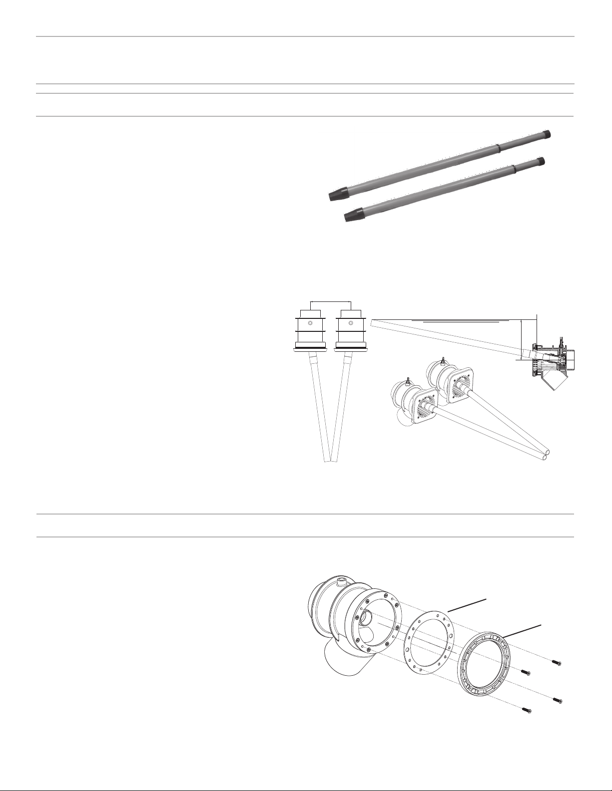
The BaduStream System is provided with a set of nozzle
adjustment tools. These tools will allow the user to set
the jet nozzles into position for optimum performance.
When setting the nozzles for basic swimming, it is
recommended that you set the nozzles in such a way
that each nozzle intersects 4 feet away while breaking
the surface at the same time. To help set the nozzles
in position for best performance, please follow these
instructions:
1. Extend the nozzle adjustment tool to full length.
2. Place each nozzle adjustment tool into the jet nozzles
on the BaduStream housing.
3. Once that is complete, bring the blue nozzle tool up to
where the end of the nozzle tool breaks the surface of
the water. Then bring the two nozzles tools together to
meet. (See Figure 16)
Nozzle Adjustment Tools
NOTE: Though the nozzle adjustment tools are designed for
outdoor use, it is advised to protect them from continuous
direct heat.
20
4 Service and Maintenance
Nozzle Adjustment
Perspective View
Water Level
~10”
Side View
Top View
10”
Figure 16
BaduStream Nozzle Adjustment
Winterizing
In areas subject to freezing water temperatures, you
should protect your equipment. We recommend you
purchase a winter cover kit part #2308752006K. This
kit includes one (1) winter plate, one (1) gasket and
four (4) screws.
Also, you can protect your swimjet system as follows:
Drain pool until water level has dropped below
the anti-entrapment cover. Then protect pump by
removing drain plug and red filler plug (or lid).
Figure 5
Winter Cover Kit
Gasket
Winter Plate
Other manuals for Badu Stream II
4
Table of contents
Other Speck pumps Lighting Equipment manuals

Speck pumps
Speck pumps BaduJet super-sport II Installation and operating instructions

Speck pumps
Speck pumps Badu Stream II Service manual

Speck pumps
Speck pumps BADU JET User manual

Speck pumps
Speck pumps Badu Stream II Service manual

Speck pumps
Speck pumps Badu Stream II Service manual

Speck pumps
Speck pumps BADU JET Service manual

Speck pumps
Speck pumps Badu Stream II User manual


