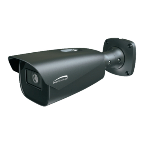
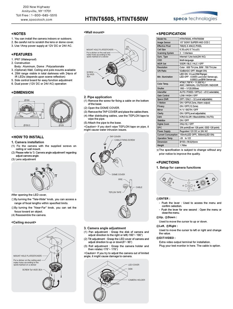
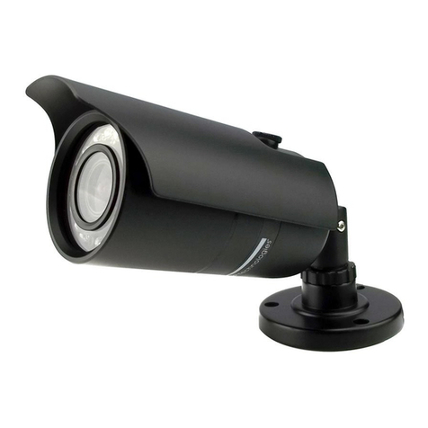
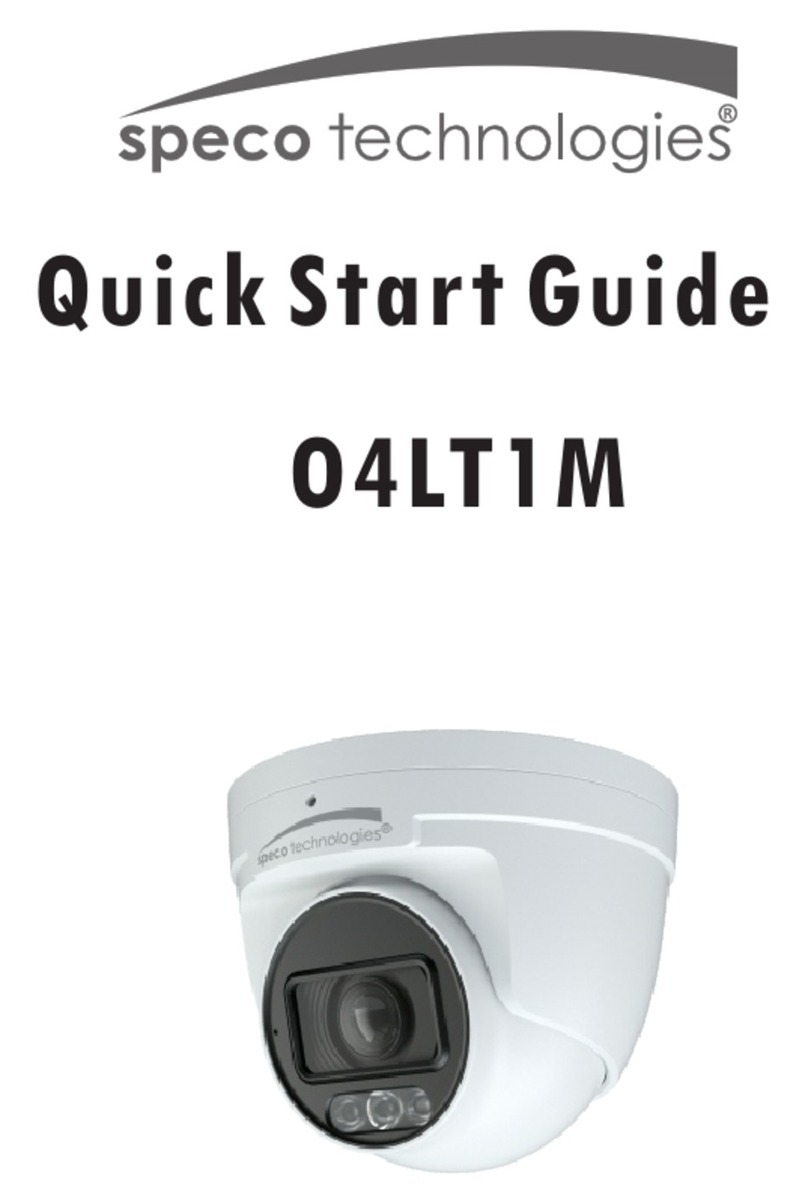
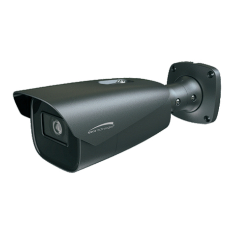
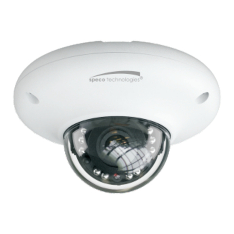
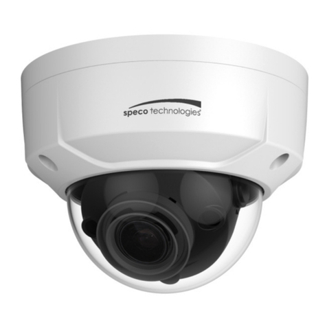
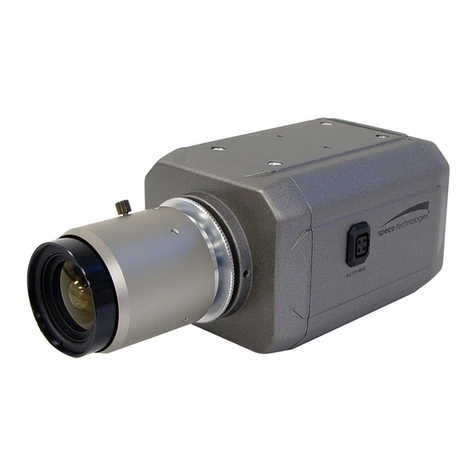
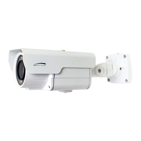
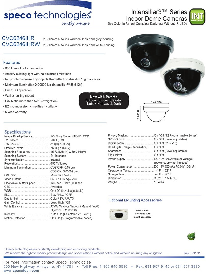
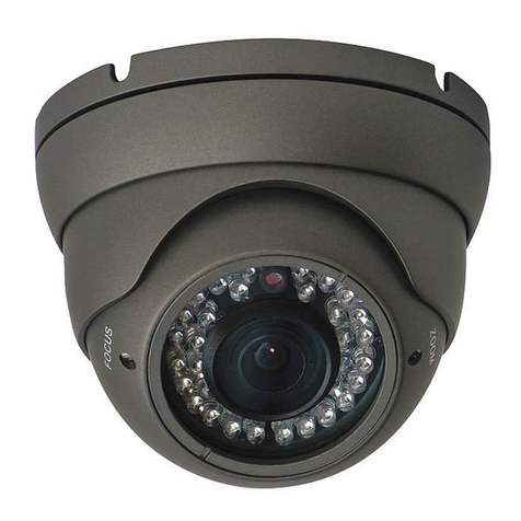
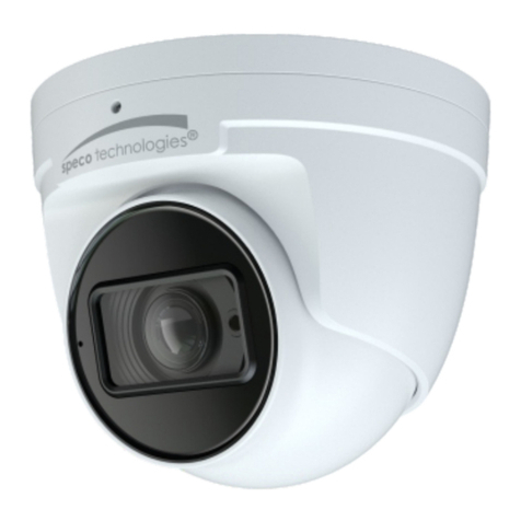
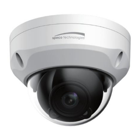
Speco LEDome User manual

LEDome
IR
DAY/NIGHT
DOME
CAMERA
EXTERNAL
IR
LEDS
&
CDS
SENSOR
BUILT-IN
HEATER
/
WEATHERPROOF
COMPOSITE
AND
UTP
VIDEO
OUTPUTS
speco
technologies
200
New
Highway
Amityville,
NY
11701
631-957-8700

ЇМОЕХ
CHECK
LIST
Check
list
EE
|
Cautions
Features
Installation
rememora
4
Adjustment
of
Led
Array
-—T
TY.
5
Operation
&
wiring
diagrams
--------------------------
6-7
Internal
Components
-----—--
————
—-—-
8
Function
Selection
-——
T
9-14
Dimension
---—
m
15
Specification
--
——
nnne
—
16
Please
make
sure
that
the
following
items
are
included
in
the
package:
LEDome
Camera
4
Mounting
Screws
1
Allen
Wrench
1
Allen
Bit
1
Video
Test
Cable
1
Power
Cable
Adaptor
(for
optional
use)
Please
leave
this
manual
with
the
end-user
for
future
reference.

Function
Selection
Function
Selection
2
.
BLC-Back
light
compensation.
Use
if
there
is
a
strong
light
or
sunshine
behind
the
object.
The
coverage
of
BLC
is
center
plus
bottom,
as
below.
3.
FIL-
Flicker
Less
ON
:
Locks
the
electronic
shutter
to
1/100
and
allows
the
auto
iris full
control
of
light
adjustment
4.
L/L-
Line
Lock
Syncs
the
camera
to
the
60
Hz
phase
of
the
electrical
circuit
Can
only
be
used
in
24-Volt
AC
operation.
If
a
camera
shows
а
wavy
or
unstable
picture
make
sure
that
L/L
is
turned
"off"
(5)
LUX
DIP
SWITCH
-M
|
15ТЕР
"a
|
2step
“Шо
|
|
3sTep
>Ш
|
4StTEP
.
LUX
DIP
SWITCH.
Tells
the
camera
when
to
switch
to
the
B/W
night
mode.
Note:
Only
one
switch
can
be
in
the
“оп”
position
at
а
time..
#1
-
The
camera
will
switch
at
1/2
lux
#2
-
The
camera
will
switch
at
1
lux
#3
-
The
camera
will
switch
at
3
lux
#4
-
The
camera
will
switch
at
5
lux
(6)
ALRAM
SWITCH
1,2
MICRO-SWITCH
FOR
ALARAM
-
Select
N/O
or
N/C

Function
Selection
Function
Selection
-
Default
settings
of
the
internal
DIP
switches
(4)
Function
DIP
SWITCH
(5)
LUX
DIP
SWITCH
-Ш
“|
ис
-.
1.
iset?
о
|
|2вс
"ai
|
25ЕТР
о
|
|
3.F/L
mi
3SETP
Ш
|
40
>Ш
4SETP
Adjust
the
DIP
switches
to
suit
the
requirements
of
your
installation.
Switch
Mode
Function
(5)
DIP
SWITCH
-M
|^
Ес
"aM
|
|
28Lc
°
|
|
3FA
>Ш
|
л
+
1.
ELC-
Electronic
light
compensation.
ON:
Electronic
Shutter
is
active
OFF
:
Electronic
shutter
is
locked
at
1/60,
and
the
DC
Auto
Iris
is
in
complete
control
of
the
light
adjustments

INSTALLATION
Adjustment
of
LED
Array
Connections:
1.
When
using
12-Volts
DC
(constant
voltage
600mA)
-CONNECT
POWER
TO
THE
POWER
JACK.
POWER
INPUT:
RED
e
Connect
CENTER:(+)
2.
When
using
24-Volts
AC
(40
VA)
-CONNECT
ACCESSORY
CABLE
TO
THE
POWER
JACK
AND
CONNECT
AC
24V
TO
THE
LEAD.
POWER
INPUT:RED
connect
CENTER:(+)
3.
CONNECT
VIDEO
CABLE
-CONNECT
BNC
CABLE
TO
THE
BNC
JACK.
YELLOW:VIDEO
[ÉT
asa
Note:
All
connections
can
be
made
directly
to
the
PCB
if
desired
4.
CONNECT
UTP
CABLE
(if
desired)
This
wires
directly
to
the
PCB
in
the
dome
housing.
PS
г
иии
Sg
UTP
+.
TP+
Adjustment
о!
LED
array
Adjustment
of
LED
Install
the
dome
camera
and
aim
the
Vari-focal
lens.
Loosen
(1-3)
Led
array
fixing
screw.
Aim
the
IR
LED
array
in
the
direction
that
the
camera
is
looking.
Connect
the
IR
LED
array
to
the
closest
connector
on
the
PCB.
Tighten
the
IR
LED
array
using
the
three
screws.
m
=
e
N
=
гі
1
Loosen
the
set-screw
located
on
both
sides
of
the
IR
LED
array
box.
2
Aim
the
IR
LED
array
in
the
same
direction
as
the
lens.
3.
Tighten
both
set-screws
on
the
IR
LED
array.

CAUTIONS
FEATURES
LEDome
should
only
be
installed
by
qualified
personnel
Please
use
only
а
24-Volt
AC
or
а
12-Volt
DC
Power
supply
To
prevent
a
fire
or
electrical
hazard
please
use
proper
power
cables
Please
make
sure
that
the
ceiling
or
wall
is
strong
enough
to
hold
the
weight
of
the
camera
The
Dome
Cover
should
be
treated
with
care
Do
not
clean
the
cover
with
an
abrasive
cleaning
material
-
Please
use
a
soft
cloth
or
tissue
to
clean
the
dome
cover
There
are
no
user-serviceable
parts
inside.
Please
do
not
disassemble
this
camera
other
than
to
make
initial
adjustments.
WEATHERPROOF
&
TAMPER-RESISTANT
DIP
SWITCHES
FOR
BLC,
ELC,
F/L
&
LINE-LOCK
DUAL
VOLTAGE:
24-VOLTS
AC
/
12-VOLTS
DC
MECHANICAL
IR
FILTER
FOR.
DAY/NIGHT
FUNCTION
1/3*
SONY
EXVIEW
CCD
SENSOR
AUTO
IRIS
DAY/NIGHT
DC
VARIFOCAL
LENS
(4mm-9mm)
TURBO
AGC
BUILT-IN
ALARM
AND
TAMPER
SWIITCHES
360
DEGREE
ADJUSTABLE
IR
LED
ASSEMBLY.
VIDEO
TEST
CONNECTOR
FOR
EASY
INSTALLATION
DAY/NIGHT
LUX
LEVEL
SELECTION
SWITCH
TO
CUSTOMIZE
YOUR
INSTALLATION
BUILT-IN
HEATERS
BUILT-IN
25
IR
LED'S
&
CDS
SENSOR
(OPTIONAL
LARGER
HEADS
ARE
AVAILABLE
FOR
GREATER
RANGE)
UTP
AND
COMPOSITE
VIDEO
OUTPUTS
HANGING
STRAP
FOR
DOME
COVER
NO
REFLECTION
FROM
THE
IR
LEDs
Note
:
Specification
are
subject
to
change
without
notice

Operation
&
wiring
diagram
Operation
&
wiring
diagram
How
to
operate
1.
Set the
direction,
zoom
and
focus
of
the
camera.
Make
any
necessary
internal
dip-switch
settings.
2.
Connect
the
video
and
power
leads.
System
Configurations:
1.
Single
system
>
3
Input
Power
2.
QUAD
system
Ly
Input
Power
Input
Power
input
Power
“es
a
—
input
Power
2.
DVR
system
ig
с

Internal
Components
Function
Selection
1.
Structure
(1)
HEATERS
(2)
IR
LED
ARRAY
(3)
DAY/NIGHT
Ты
ч
DC
Auto
Iris
M
I
d
Lens
4~9MM
(1)
HEATERS
To
prevent
moisture
and
extend
the
operating
range
of
the
camera.
The
heaters
are
thermostatically
controlled.
(2)
IR
LED'S
Infrared
LED'S
activate
needed.
Optional
heads
are
available.
(3)
DAY/NIGHT
DC
AUTO-IRIS
LENS
Mechanical
IR
filter
exchange
Adjust
between
T€
2W
(TELE
€>
WIDE)
to
set
the
angle
(focal
length)
Set
the
focus
by
adjusting
-€>3N
NOTE:
BOTH
OF
THE
ABOVE
ADJUSTMENTS
GET
LOCKED
INTO
POSITION
THROUGH
THE
USE
OF
"LOCKING
HANDLES".
(1)
VIDEO
TEST
TERMINAL
(2)
V-PHASE
(3)
DC
IRIS
LEVEL
(4)
DIP
SWITCH
(5)
LUX
DIP
SWITCH
(6)
ALARM
SWITCH
1,2
(1)
VIDEO
TEST
TERMINAL
Allows
you
to
connect
a
test
monitor
for
making
adjustments.
(2)
V-PHASE
LEVEL
When
desired.
the
vertical
phase
may
be
adjusted
to
sync
the
vertical
phase
of
the
camera
with
other
cameras
in
the
sys-
tem.
This
feature
is
only
available
in
24
volt
AC
operation.
(3)
DC
IRIS
LENS
LEVEL
DC
IRIS
level
adjustment
for
the
auto
iris
lens.

DIMENSION
SPECIFICATION
OD
.
2
GOGOOOOG
Осо
IMAGE
SENSOR
1/3"
SONY
EX-VIEW
CCD
TV
SYSTEM
NTSC
SCANNING
SYSTEM
2:1
INTERLACED
SYNG
SYSTEM
LINE
LOCKED/ADJUSTABLE
V-PHASE
LINE
LOCK
INTERNAL
ON-OFF
RESOLUTION
MINIMUM
ILLUMINATION
480
TV
LINES
0.03
LUX(IR
OFF)
0.00
(IR
ON)
CDS
SENSOR
SIN
RATIO
PHOTOCONDUCTIVE
CELLS
ADJUSRABLE
IN
4
STEPS
MORE
THAN
5048
GAMMA
CHARACTERISTIC
VIDEO
OUTPUTS
1.0Vp-p
-
75ohm
COMPOSITE
-
UTP
Balun
built-in
|
ELECTRONICSHUTTER
|
SHUTTER
POWER
REQUIREMENTS
045
1/60-1/100,000
sec
24-Volls
AC
!
12-Volts
DC
POWER
CONSUMPTION
OPERATIONAL
TEMPERATURE
-40F
to
+122F
WEIGHT
22
Pounds

WARRANTY
MEMO
LIMITED
WARRANTY
TS
WARRANTY
IS
VALID
ONLY
ON
PRODUCTS
PURCHASED
AND
USED
IN
THE
UNITED
STATES
OF
AMERICA.
THS
WARRANTY
APPLIES
ONLY
TO
THE
ORIGINAL
USER.
‘SUBJECT
TO
CONDITIONS
AND
EXCLUSIONS
FOUND
BELOW,
THIS
PRODUCT
IS
WARRANTED
AGAINST
MANUFACTURING
DEFECTS
IN
MATERIAL
AND
WORKMANSHIP
FOR
THE
FOLLOWING
PERIOD
FOR
PARTS
AND
LABOR.
PRO.
VIDEO
CAMERAS:
2
YEARS
PRO-VIDEO
MONITORS:
A
YEAR
BALANCE
OF
PRO-VIDEO
LINE:
л
VEAR"
"Time lapse
VER
Orum
Assemblies
and
Meads:
$0-0AY8
WE
WILL
REPAIR
OR
REPLACE
(AT
OUR
OPTION)
ANY
PARTS
FOUND
TO BE
DEFECTIVE
FOR
THE
WARRANTY
PERIOD
SPECIFIED.
WE
WILL
PROVIDE
A
REPLACEMENT
FOR ANY
DEFECTIVE
PART.
sonomons
THS
WARRANTY
WILL
BE
HONORED
ONLY
ON
THE
PRESENTATION
OF
THE
ORIGINAL
DATED
BLOF
SALE
.
TRANSPORTATION
OF
THE
PRODUCT
то
OUA
SERVICE
STATON
B
HE
RESPONSIBILITY
OF
THE
USER
REPAIRED
OR
REPLACED
PRODUCT
VILL
BE
RETURNED
PREPAID
DURING
THE
WARRANTY
PORE,
EXCLUSIONS
‘THIS
WARRANTY
SHALL
NOT
COVER
ADJUSTMENT
OF
CUSTOMER
OPERATED CONTROLS
AS
EXPLAINED
IN
THE
APPROPRIATE
MODEL'S
INSTRUCTION
MANUAL
OR
PRODUCTS
WHICH
HAVE
BEEN
ALTERED,
ABUSED,
OR
HAVE
MISSING
OR
ALTERED
SERIAL
NUMBERS.
2.
TWS
WARRANTY
SHALL
NOT
APPLY
TO
UNCRATING,
SETUP,
INSTALLATION,
OR
THE
REMOVAL
AND
REINSTALLATION
OF
PRODUCTS
AFTER
REPAIR.
2.
THiS
WARRANTY
SHALL
NOT
APPLY
YO
REPAIRS
OR
REPLACEMENTS
NECESSITATED
BY
ANY
CAUSE
BEYOND
THE
RESULT
OF
MANUFACTURE
INCLUDING.
BUT
NOT
LIMITED
TO,
ANY
MALFUNCTION,
DEFECTS
OR
FAILURE
CAUSED
BY
OR
RESULTING
FROM
UNAUTHORIZEO
SERVICE
OR
PARTS,
MPROPER
MAINTENANCE,
MODIFICATION
OR
REPAIR
BY
THE
USER,
ABUSE,
MISUSE,
NEGLECT,
ACCIDENT,
FIRE.
FLOOD
OR
OTHER
ACTS
OF
GOD.
INCORRECT
UNE
VOLTAGE.
DAMAGE
OR
MAGE
BURNS
TO
TELEVISION
PICTURE
TUBES
CAUSED
BY OR
ATTRIBUTABLE
TO
THE
USE
OF
ANY
ACCESSORY,
ELECTRONICS
GAME
OR
DEVICE,
OR
DAMAGE
CAUSED
TO
IMAGE
PICKUP
TUBES
BY
EXCESSIVE
LIGHT.
THE
FOREGOING
1
IN
LIEU
OF
ALL
OTHER
EXPRESSED
WARRANTIES
AND
WE
DO
NOT
AUTHORIZE
ANY
PARTY
TO.
ASSUME
FOR
US
ANY
OTHER
OBLIGATION
OR
LIABILITY.
IN
NO
EVENT
SMALL
WE
BE
LIABLE
FOR
INCIOENTAL
OR
‘CONSEQUENTIAL
DAMAGES
ARISING
FROM
THE
USE
OF
THIS
PRODUCT,
OR
FOR
ANY
DELAY
IN
THE
USE
OF
THES
PRODUCT
DUE
TO
CAUSES
BEYOND
OUR
CONTROL.
SOME
STATES
DO
NOT
ALLOW
LIMITATIONS
OF
HOW
LONG
АМ
IMPLIED
WARRANTY
LASTS
ANDIOR
DO
NOT
ALLOW
THE
EXCLUSION
OR
LMITATION
OF
CONSEQUENTIAL
DAMAGES.
THE
ABOVE
LIMITATIONS
ON
IMPLIED
WARRANTY
AND
CONSEQUENTIAL
DAMAGES
MAY
NOT
APPLY
TO
YOU.
Тиз
WARRANTY
GIVES
YOU
SPECIFIC
LEGAL
RIGHTS.
YOU
MAY
HAVE
OTHER
RIGHTS
WHICH
VARY
FROM
STATE
TO
STATE.
NOTE:
FOR
YOUR
PROTECTION
IN
THE
EVENT
OF
THEFT
OR
LOSS
OF
THIS
PRODUCT.
PLEASE
FILL
IN
THE
INFORMATION
REQUESTED
BELOW
AND
RETAIN
WITH
YOUR
SALES
RECEIPT.
MODEL
NO.
+
SERIAL
NO.
3
(LOCATED
ON
BACK
OR
BOTTOM
SIDE
OF
UNIT]
DATEOFPURCHASE:
—
WHERE
PURCHASED:
—
PURCHASE
PRICE:
—
FOR
MORE
INFORMATION
REGARDING
SERVICE
OR
RETURN,
CALL
US
AT
TOLLFREE:
1400245
5516
IN
METRO
NY:
601-867-8709
ALWAYS
USE
DISCRETION
WHEN
INSTALLING
VIDEO
AND/OR
AUDIO
SURVEILLANCE
EQUIPMENT
ESPECIALLY
WHEN
THERE
IS
PERCEIVED
PRIVACY,
OR
AN
EXPECTATION
OF
PRIVACY.
INQUIRE
REGARDING
FEDERAL,
STATE
AND/OR
LOCAL
REGULATIONS
APPLICABLE
TO
THE
LAWFUL
INSTALLATION
OF
VIDEO
AND/OR
AUDIO
RECORDING
OR
SURVEILLANCE
EQUIPMENT.
PARTY
CONSENT
MAY
BE
REQUIRED.
Other manuals for LEDome
1
Table of contents
Other Speco Security Camera manuals

Speco
Speco O2P20X User manual

Speco
Speco H2AB2 User manual

Speco
Speco O8FB1M User manual

Speco
Speco O4DT7 User manual

Speco
Speco CVC6146SCFF User manual

Speco
Speco VLEDB1HG/W Series User manual

Speco
Speco HINT13D7G User manual

Speco
Speco O4DT1 User manual

Speco
Speco O4FT2W User manual

Speco
Speco O2VT1V User manual

Speco
Speco O4VFBM User manual

Speco
Speco VL-62 User manual

Speco
Speco O4VT1NG User manual

Speco
Speco INTENSIFIER3 CVC6246IHR User manual
Speco
Speco VL-12 User manual

Speco
Speco CVC5100BPVF User manual

Speco
Speco HLPR1TW User manual

Speco
Speco O5LT1 User manual

Speco
Speco VL-562SD User manual

Speco
Speco H5T1M User manual