Phihong POE75U-1UP-N-R User manual

Phihong Midspan POE with TCPIP (SNMPv2c)
User Manual
TCPIP (SNMPv2c) Rev 1.8
Compliant Models:
POE75U-1UP-N-R
POE240U-1MP-N-R
POE240U-2MP-N-R
POE240U-4BT-N-R
POE125U-4AT-N-R
POE240U-4UP-N-R
POE576U-8BT-N-R
POE576U-4MP-N-R
POE576U-8UP-N-R
POE806U-8BT-N-R
POE806U-8MP-N-R

Phihong USA Corporation | 47800 Fremont Blvd., Fremont, CA 94538 | 1.510.445.0100 | www.phihong.com
1
Disclaimer
Phihong accepts no accountability or liability arising from the use of the Midspans, as described
in this document. The handling of equipment will be users’ responsibility. Applications described
in this document are for descriptivepurposes only. Phihong does not provide warranty for modified
products.
Notice
This document contains informative information about the software and hardware used on the
Midspan. The information is held to be accurate and reliable from time of print. Please be advised
that product development and revisions are still in course of action. Phihong cannot be held
responsible for involuntary error, exclusions, inaccuracies, or following changes of printed
material.
Phihong reserves the right to make changes to products and to their specifications as described in
this document, at any time, without prior notice. The contents of this document may not be
photocopied or reproduced in any form without written permission of Phihong.
NOTE: Midspans are for indoor use only!
© August 2020 Phihong USA Corp.
All Rights Reserved.
This document is subject to change without notice.

Phihong USA Corporation | 47800 Fremont Blvd., Fremont, CA 94538 | 1.510.445.0100 | www.phihong.com
2
Contents
Overview ........................................................................................................................................4
1. Safety Procedures ......................................................................................................................5
1.1. General Precautions ............................................................................................................5
2. Midspan Hardware Setup ........................................................................................................7
2.1. Physical Hardware Appearance ...........................................................................................7
2.2. Connecting Ethernet Cables ................................................................................................9
2.3. Powering Up Midspan .......................................................................................................10
2.4. LED Indicators ...................................................................................................................13
2.5. Technical Specifications.....................................................................................................14
3. Midspan Monitoring and Control --- HTTP Protocol .........................................................15
3.1. Port Control Webpage .......................................................................................................15
3.2. Administrative Management Webpage ..............................................................................18
3.3. Network Settings Webpage ................................................................................................18
3.4. SNMP Community String Webpage .................................................................................20
3.5. System Tools Webpage .....................................................................................................21
4. Midspan Monitoring and Control with MIB Browser --- SNMP Protocol .......................23
4.1. Structure of Management Information (SMI) of Phihong Midspan ..................................23
4.2. Phihong Midspan MIB .......................................................................................................25
4.3. Notes for Using Phihong Midspan MIB ............................................................................28
4.4. Using MG-SOFT MIB Browser to run Phihong Midspan ................................................28
5. Field Firmware Updating .......................................................................................................36
5.1. Updating Microprocessor Flash Contents with POEA-x.x.bin .........................................36
5.2. Updating EEPROM Contents with POEB-x.x.bin ............................................................39
6. Troubleshooting ......................................................................................................................41
7. Frequently Asked Questions ..................................................................................................42

Phihong USA Corporation | 47800 Fremont Blvd., Fremont, CA 94538 | 1.510.445.0100 | www.phihong.com
3
List of Figures
Figure 1 –Single Port Midspan Ports .............................................................................................7
Figure 2 –Single Port Midspan AC Input ......................................................................................7
Figure 3 –Multiport Midspan Ports ............................................................................................... 8
Figure 4 –Multiport Midspan AC Input......................................................................................... 8
Figure 5 –Single Port Midspan SNMP Connection........................................................................9
Figure 6 –Single Port Midspan Data and PoE Connections...........................................................9
Figure 7 –Multiport Midspan SNMP Connection .......................................................................10
Figure 8 –Multiport Midspan PoE Connections ..........................................................................10
Figure 9 –AC Cord .......................................................................................................................10
Figure 10 –Single Unit Rack Mount ............................................................................................11
Figure 11 –Two Units in Side by Side Rack Mounting ...............................................................11
Figure 12 –19” Midspan Rack Mount .........................................................................................11
Figure 13 –Rack Mounting Brackets and Screws .......................................................................11
Figure 14 –Management Set-up Diagram ....................................................................................15
Figure 15 –Port Control Webpage ...............................................................................................15
Figure 16 –Administrative Management Webpage .....................................................................18
Figure 17 –Network Settings Webpage .......................................................................................19
Figure 18 –Reboot Webpage .......................................................................................................20
Figure 19 –SNMP Community Strings Webpage ........................................................................20
Figure 20 –System Tools Webpage .............................................................................................22
Figure 21 –Phihong Midspan SMI ...............................................................................................23
Figure 22 –Phihong Midspan SMI Continued .............................................................................24
Figure 23 –Generate Phihong SNMPv2c MIB Module ...............................................................30
Figure 24 –Set SNMP Protocol to contact remote SNMP Agent ................................................31
Figure 25 –Phihong Midspan MIB Tree ......................................................................................32
Figure 26 –Set IP Address of Trap Receiver ...............................................................................34
Figure 27 –Trap Ringer Console ..................................................................................................35
Figure 28 –TFTP Uploading Using Application Entry Mode......................................................37
Figure 29 –Set Static IP in Internet Protocol (TCP/IP) Properties Window ................................38
Figure 30 –Upload in Internet Explorer .......................................................................................39
Figure 31 –Software Update Successful Window .......................................................................40
Figure 32 –Upload Using System Tools on Web Interface .........................................................40

Phihong USA Corporation | 47800 Fremont Blvd., Fremont, CA 94538 | 1.510.445.0100 | www.phihong.com
4
Overview
Phihong’s midspans are Power over Ethernet (PoE) injectors with output options ranging from
15.4W to 95W per port. Available with 1, 2, 4, 8, 16 or 24 ports, Phihong’s midspans put out full
power every port with no need to manage power across ports.
By using the SNMPv2C (Simple Networking Management Protocol version 2C) protocol, users
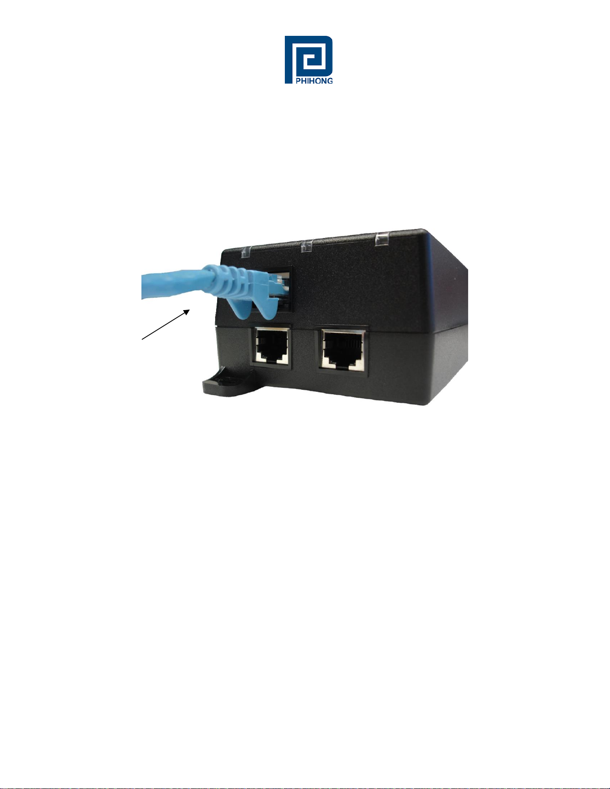
can monitor and control the port status over their internet browser. Linking an Ethernet cable
between their midspan and management computer, locally or otherwise through a network switch,
users may manage certain functions including remote reset of powered devices. Users may connect
to their midspan using the DHCP client on the midspan which will create a dynamic hostname and
IP address unique to the network. Otherwise a Static IP address may be created by the user.
Internet browsers that users may choose from to access their Phihong midspans including: Internet
Explorers 7 and 8 found on Windows XP, Windows Vista and Windows 7. Mozilla Firefox,
Google Chrome, Opera and Safari may also be used. To update the firmware on your midspan,
only Microsoft XP or Vista may be used at this time. Please check www.phihong.com for support
updates or contact us at usasales@phihongusa.com for additional questions regarding
compatibility. For SNMO interface, users may refer to the SNMP console manual for PC
requirements.
A default username and password come preset on your Phihong midspan. Entering “admin” in
both fields will allow users to gain access to customize their security settings. The default read-
only community string is “Phihong_read_only” and users may enter “Phihong” for the read-write
community field. Select tools that users may access through Phihong’s management interface is
port control (i.e. turn on/off), change access strings (hostname, username, password etc.), and set
IP Address to dynamic DHCP to allow it to be set automatically or Static as customized by the
user. Additionally, users may configure and send SNMPv2C TRAPs which are triggered on
changes to port status.
Phihong may release new firmware and updates at any time, so it is advised to check our websites
regularly for any updates that may affect your midspan. For the models listed on the cover page,
two firmware files are used. The first is POEA-x.x.x.bin which is uploaded to an internal
microprocessor under Windows TFTP command. The second is POEB-x.x.x.bin which is
uploaded directly into an internal EEPROM by entering http://hostmane/upload into your internet
browser or by using web <system tools>.
More detailed instruction may be found in this manual.

Phihong USA Corporation | 47800 Fremont Blvd., Fremont, CA 94538 | 1.510.445.0100 | www.phihong.com
5
1. Safety Procedures
1.1. General Precautions
General –Please read the following precautions carefully before installing and connecting the
system to a power source.
Note –Only qualified and trained service personnel (in accordance with IEC 60950 and AS/NZS
3260) should install, replace, or service the equipment. Install the system in accordance with
Country, National or to the U.S. National Electric Code if you are in the United States.
Precautions:
1. The building facilities in which the product will be used requires a fuse or circuit breaker
no larger than 15A for 120Vac (U.S.A.) or 10A, 230Vac (international). The building
facilities must protect the Midspan from over current and short-circuits.
2. Before connecting the Midspan to a power source (including power cord requirements),
read the Midspan Hardware Setup procedure in Section 2. This procedure as with all
procedures and instructions can be found in the Midspan User Manual. To download a
copy of the Manual, visit www.phihong.com.
3. To prevent the Midspan from overheating, do not operate the product in an area that
exceeds the maximum recommended ambient temperature of 40oC. Allow at least 3 to 4
inches of clearance around all ventilation openings.
4. In order to support the midspan’s weight, do not stack the chassis on any other equipment.
Shelf mounted equipment requires a stable and durable surface. When installed, do not
push or pull on the Midspan when the equipment is installed.
5. The Midspan consists of two rows of “Data” and “Data & Power” ports. The ports use RJ-
45 data sockets. Do not connect telephone cables into these ports. Only RJ-45 data cables
may be connect to these sockets.
6. Do not work on the Midspan system or connect or disconnect the cables, during periods of
lightning activity.
7. The AC plug/socket combination must be accessible at all times, as it serves as the main
disconnect device to the product.
8. Before servicing the product, always disconnect the products from its AC and DC source.
9. Disposal of this product should abide by all appropriate National laws and regulations.

Phihong USA Corporation | 47800 Fremont Blvd., Fremont, CA 94538 | 1.510.445.0100 | www.phihong.com
6
1.1 Sicherheitsmaßnahmen –Allgemeine Vorsichtsmaßnahmen
Allgemein –Lesen Sie die folgenden Vorsichtsmaßnahmen sorgäfltig durch, bevor Sie das System
installieren und an eine Energiequelle anschließen.
Hinweis –Das Gerät derf nur durch qualifiziertes und geschultes tehisches Personal (gemäß IEC
60950 [Vorschrift 60950 der Internationalen Elektrischen Kimmission] und AS/NZS 3260
[Vorschrift für Australien und Neuseeland]) installiert, ersetzt oder repariert werden. Installieren
Sie das System auch in Übereinstimmung mit den geltenden nationalen oder europäischen
Vorschriften bzw. Der NEC-Vorschrift, falls Sie sich in den Vereinigten Staaten befinden.
Vorsichtsmaßnahmen:
1. Die Gebäudeinstallationen, in denen das Produkt benutzt wird, müssen über eine Sicherung
oder einen Schutzschalter mit maximal 15A für 120 Vac (USA) oder 10A für 230Vac
(ineternational) verfügen. Dis Gebäudeinstallationen müssen das Midspan-Device vor zu
starkem Strom oder Kurzchlüssen schützen.
2. Lesen Sie vor dem Anschließen des Midspan-Device an eine Energiequelle (einschließlich
der erforderlichen Anschlussleitungen) die Setup-Anleitung für Ihre Midspan-Hardware in
Kapitel 2 genau druch. Dieses Verfahren wird zusammen mit allen weiteren Vorgängen
und Anwisungen im Benutzerhandbuch für das Midspan-Device beschrieben. Sie Können
das Benutzerhandbuch unter www.phihong.com herunterladen.
3. Um das Midspan-Device vor Überhitzung zu schübenutzen Sie das Produkt nicht in
Räumen, die die maximale empfohlene Umgebungstemperatur von 40oC überschreiten.
Lassen Sie um alle Lüftungsöffnungen herum mindestens 7,5 bis 10 cm (3-4 inches) frei.
4. Stützen Sie das Gewicht des PoE Midspan-Device nicht ab, indem Sie das Gehäuse auf ein
anderes Gerät stellen. Falls Sie das Gerät auf ein Gestell montieren,muss dieses eine stabile
und haltbare Oberfläche haben. Nach der Installation des Systems bewegen Sie das
Midspan-Device nicht mehr.
5. Ds Midspan-Device enthält zwei Reihen mit “Datenports” und “Daten-und-Stromports.”
Die Ports verwenden RJ45-Datenanschlüsse. Schließen Sie keine Kabel an und trennen Sie
keine Kabelverbindungen während Gewittern mit Blitzen.
6. Führen Sie an dem Midspan-System keine Arbeiten durch schließen Sie keine Kabel an
und trennen Sie keine Kabelverbindungen während Gewittern mit Blitzen.
7. Der Steckanschluss Wechselstrom muss jederzeit zugänglich sein, da er als
Haupttrenngerät für das Produkt dient.
8. Trennen Sie das Produkt immer erst von der Stromquelle, bevor Sie Wartungs- oder
reparaturarbeiten daran durchführen.

Phihong USA Corporation | 47800 Fremont Blvd., Fremont, CA 94538 | 1.510.445.0100 | www.phihong.com
7
9. Entsorgen Sie dieses Produkt gemäß aller geltenden Gesetze und Vorschriften Ihres Landes
und der EU (falls Sie sich in einem Land der EU befinden).
2. Midspan Hardware Setup
2.1 Physical Hardware Appearance:
2.1.1 Single Port Models
Front View:
Rear View:
NIC
Connector
Port
PoE
OUT
Data
IN
IEC320 C14
AC Input
Figure 1: Single Port Midspan Ports

Phihong USA Corporation | 47800 Fremont Blvd., Fremont, CA 94538 | 1.510.445.0100 | www.phihong.com
8
2.1.2 Multi Port Models
Front View:
Figure 3: Multiport Midspan Ports
Rear View:
Figure 4: Multiport Midspan AC Input
Row 1: Data and Power OUT to
powered devices
Row 2: Data IN from Network
Switch
NIC Management Port
AC Input: IEC320
C14
Figure 2: Single Port Midspan AC Input

Phihong USA Corporation | 47800 Fremont Blvd., Fremont, CA 94538 | 1.510.445.0100 | www.phihong.com
9
2.2 Connecting Ethernet Cables*
2.2.1 Single Port Models
NIC Connection
Figure 5: Single Port Midspan SNMP Connection
Ports Connection
NIC Port Connected
to management
computer

Phihong USA Corporation | 47800 Fremont Blvd., Fremont, CA 94538 | 1.510.445.0100 | www.phihong.com
10
Figure 6: Single Port Midspan Data and PoE Connections
*Ethernet cables are not included.
2.2.2 Multi Port Models
NIC Connection
Figure 7: Multiport Midspan SNMP Connection
Ports Connection
POE
OUT
Data IN from
Network Switch
Diagnostic LEDS
NIC Port Connected
to management
computer

Phihong USA Corporation | 47800 Fremont Blvd., Fremont, CA 94538 | 1.510.445.0100 | www.phihong.com
11
Figure 8: Multiport Midspan PoE Connections
2.3 Powering Up Midspan
AC power cord*:
The AC power cable is connected to the AC power connector located in the rear side of the
Midspan and the power outlet.
*AC Power Cord may be ordered separately.
POE OUT
Connected to valid load
Figure 9:AC Cord

Phihong USA Corporation | 47800 Fremont Blvd., Fremont, CA 94538 | 1.510.445.0100 | www.phihong.com
12
2.3.1 Rack Mounting Options
Plastic Case Multiport Units
Multiport plastic case midspans may be rack mounted on a 19”1U rack in either single or double
unit mounts. To position the Midspan on the rack; arrange the mounting bracket to the corresponding
screw holes on the Midspan. Keep the screw area visible to insert screws, and then tighten the screws.
Screws and brackets will beincluded in the package. For replacement parts contact Phihong for part number
POE125U-ACCY01-R.
Figure 10: Single Unit Rack Mount
Figure 11: Two Units in Side by Side Rack Mounting
Figure 12: 19” Midspan Rack Mount
Figure 13: Rack Mounting Bracket and Screws

Phihong USA Corporation | 47800 Fremont Blvd., Fremont, CA 94538 | 1.510.445.0100 | www.phihong.com
13
Power Cord Requirements:
Power cords must meet the requirements for the country it is intended to be used.
U.S.A. and
Canada
▪The cord must have a minimum of 10A rated current competence
▪The cord must be CSA or UL approved
▪The minimum requirement for the flexible cord is:
o18 AWG (10A)
oThree-Conductor (Line, Neutral, Ground)
oType SV (stranded Vacuum Rubber Jacketed) or SJ
(stranded Junior Rubber Jacketed) or SVT (Stranded
Vacuum Rubber Jacketed Thermoplastic) or SJT (Stranded
Junior Thermoplastic)
▪The plus must be earth-grounded with a NEMA 5-15 (15A, 125V) or
NEMA 6-15P (15A, 250V) configuration
Europe
Switzerland
▪The supply plug must comply with SEV/ASE 1011
Denmark
▪The supply plug must comply with section 108-2-D1, standard DK2-
1a or DK2-5a
United Kingdom
▪The Midspan is covered by General Approval (section 16.16.060,
NS/G/12345/J100003, for indirect connection to a public
telecommunication system
France and Peru
▪IT equipment cannot power this device. In the case of an IT powered
device, the unite needs to be powered by 230V through an isolation
transformer with a ratio of 1:1 and the secondary connection
(Neutral) is properly grounded
▪The Midspan must have access to a nearby power outlet. By disconnecting the power cord
from the outlet, you will eliminate power from the device.
▪The flexible cord that connects to the Midspan must have a configuration to connect with an
EN60320/IEC320 inlet connector.
▪According to the EN60950/IEC 950 specifications this device functions under SELV (Safety
Extra Low Voltage) conditions. The conditions are true if the equipment and the connected
device functions under SELV conditions.

Phihong USA Corporation | 47800 Fremont Blvd., Fremont, CA 94538 | 1.510.445.0100 | www.phihong.com
14
Power up Midspan:
In order to power up your midspan insert an AC power cord into the appropriate connector on the
rear of your midspan. Once the cord is connected to a universal or redundant power source the
midspan will turn on.
With AC power applied, the unit starts-up and all LEDs should illuminate. The device runs through
a quick power-on test, which takes a couple of seconds. During this period, all ports are initially
disabled and the port indicators light up. After completing the cold start, ports will operate under
normal conditions and the unit is ready to connect to powered devices.
2.4 LED Indicators:
Port LED:
Model POE75U-1UP-N-R has three LED indicators labeled “ON”, “FAULT”, and “CONNECT”.
The “ON” LED will illuminate a solid green to indicate that the AC connection is good and that
unit is sufficiently powered. The “CONNECT” LED will illuminate solid green if it detects a
device that requires more than 33.6W of power (12.5K-resistance). The “CONNECT” LED will
illuminate a blinking green if it detects a device requiring less than 33.6W of power (25K resistance)
and will power in IEEE802.3at mode. Should a fault occur with the connections; the yellow Fault
LED will blink till the error is resolved. For a full description of the LED diagnostics, please review
the individual product datasheet on www.phihong.com.
For the series of multiport midspans, for each port the left LED (as viewed from front) will be
blinking (green) if 25K-resistance load is detected, meaning that the powered device requires less
than 33.6W of power and the midspan has powered in “IEEE802.3at mode”. The LED will
illuminate in solid green if the powered device requires more than 33.6W of PoE and the midspan
has powered up in Full Power mode. The right LED will blink Yellow if a fault has occurred with
the connection. No LEDs will illuminate if the port is not connected.
NIC LED:
If both LEDs are off, it indicates that Midspan is disconnected from the network.
If the green LED is illuminated and the orange LED blinks, it indicates the Midspan is properly
connected to the network.

Phihong USA Corporation | 47800 Fremont Blvd., Fremont, CA 94538 | 1.510.445.0100 | www.phihong.com
15
2.5 Technical Specifications
Model Name:
General Electrical Specifications:
• Input
AC Input Voltage Rating
100VAC to 240VAC
AC Input Voltage range
90VAC to 264VAC
AC Input Current
Varies per model
AC Input frequency
47Hz to 63Hz
Max. In-rush current
30A for 115VAC at Max. load
60A for 230VAC at Max. load
• Output
POE
125U-
4AT-N
POE
75U-
1UP-N
POE
240U-
1MP-N
POE
240U-
2MP-N
POE
240U-
4BT-N
POE
240U-
4UP-N
POE
576U-
8BT-N
POE
576U-
8UP-N
POE
576U-
4MP-N
POE
806U-
8BT-N
POE
806U-
8MP-N
Nominal DC Output Voltage
56V
56V
56V
56V
56V
56V
56V
56V
56V
56V
56V
Output Power per Port
33.6W
75W
95W
95W
60W
60W
75W
75W
95W
90W
95W
Maximum Current per Port
0.6A
1.339A
1.696A
1.696A
1.071A
1.071A
1.339A
1.339A
1.696A
1.607A
1.696A
• Detection resistance
POE
125U-
4AT-N
POE
75U-
1UP-N
POE
240U-
1MP-N
POE
240U-
2MP-N
POE
240U-
4BT-N
POE
240U-
4UP-N
POE
576U-
8BT-N
POE
576U-
8UP-N
POE
576U-
4MP-N
POE
806U-
8BT-N
POE
806U-
8MP-N
25K
12.5k and 25K
12.5K
and per
IEEE
802.3 BT
Standard
12.5k and
25K
12.5K
and per
IEEE
802.3 BT
Standard
12.5k and
25K
12.5k and
25K
12.5K
and per
IEEE
802.3 BT
Standard
12.5k and
25K
For detailed specifications, refer to the datasheets posted on www.phihong.com

Phihong USA Corporation | 47800 Fremont Blvd., Fremont, CA 94538 | 1.510.445.0100 | www.phihong.com
16
3. Midspan Monitoring and Control --- HTTP Protocol
Use Cat5e cables or better to connect both PC and Midspans to the network as follows:
3.1 Port Control Webpage
Enter the hostname in the address bar of your internet browser (The default value of hostname is
phihong-xxxxxx, where xxxxxx is the last 6 letters of the Midspan’s MAC address found on the
midspan’s label), then enter the username and password in the login screen. The default username
and password are both “admin”. Users should note that when creating their new username and
password both are case sensitive. The Port Control Webpage will be displayed as follows:
Figure 14: Management Set Up Diagram
Figure 15: Port Control Webpage

Phihong USA Corporation | 47800 Fremont Blvd., Fremont, CA 94538 | 1.510.445.0100 | www.phihong.com
17
Model Name:
This can be found in the upper left corner of the Port Control page.
Heartbeat:
The Heartbeat is a diagnostic tool to assess the quality of the connection between the midspan and
the network. A blinking blue “Communication Okay” will indicate that the midspan is connected
to the network and that data is being relayed correctly. Should a fault occur with the connection;
the blinking will stop and a solid red “Communication Lost” will appear on the screen.
Hostname, IP address, Firmware version and MAC address display:
These can be found on the first row of the table located in the middle of the Port Control Page.
Menu:
The menu on the left side of webpage consists of Port Control and Configuration Settings including:
Administrative Management, Network, SNMP, System Tools and Logout. These will be explained
in detail later in this manual.
Help Info:
Located in the lower right-hand corner of the screen, users may click the Help Info icon to obtain
contact information for technical support. Users may also find support documents and contact
information on www.phihong.com.
Print Tools:
To the left of the Help Info icon is the Print Tools icon. Clicking on this icon will print the current
webpage. The default printer must be on the same network as the midspan in order to use this
function.
Phihong webpage:
Clicking on any of the Phihong logos will link directly to www.phihong.com, where the detailed
information for all Phihong products, including support information and datasheets, can be found.
Port Monitoring and Control:
At the center of the Port Control webpage, there is a table for the user to monitor and control port
status.
•Click on the control button “On”in each row, the corresponding port Output-LED will be
turned on if connected to a valid load, or it will display “No Connection”.
•Click on the control button “Off”in each row, the corresponding port Output-LED will be
turned off.

Phihong USA Corporation | 47800 Fremont Blvd., Fremont, CA 94538 | 1.510.445.0100 | www.phihong.com
18
•Click on the control button “Cycle”in each row to reset that port, if the corresponding port
Output-LED is already on (or No Connection), it will be turned off for several seconds and
then turned on again (or No Connection). If the Output-LED is off, it will be turned on (or
No Connection).
•Click the button Enable All Ports below the table, the port Output-LEDs will be turned
on if connected to a valid device or it will display a status “No Connection” if a port is not
connected to a valid end device.
•Click the button Disable All Ports below the table, all port Output-LEDs will be turned
off.
•Click the button Cycle All Ports in the last row, all port Output-LEDs will follow one of
the following actions: If the ports are already “ON” then the ports will be “On” (or No
Connection) →Off →Turning On… →On (or No Connection). If all ports start turned
off then the sequence will be Off →Turning On… →On (No Connection), depends on
their original states.

Phihong USA Corporation | 47800 Fremont Blvd., Fremont, CA 94538 | 1.510.445.0100 | www.phihong.com
19
3.2 Administrative Management Webpage
Clicking Admin Management under the Configuration menu will bring you to the following page.
From here the user can choose their own username and password to login to their Phihong Midspan
web controller. Enter in the new username and password in the corresponding box and click on
the Save button. Remember to write down your new login information in a safe place for reference.
If you forget your login information, please review Section 7 –Frequently Asked Questions.
• Both the username and the password must have a character length of 5 –30 inclusive.
• Valid characters include: 0-9, A–Z, and !@#$%^&*()-_+~?<>,.
Figure 16: Administrative Management Webpage
3.3 Network Settings Webpage
Clicking on the Network button under the Configuration menu will direct to the Network Settings
page. This webpage allows the user to change the midspan’s hostname and configure network
settings.
Change hostname:
A user may select any character from the keyboard for a hostname up to 15 characters maximum.
Any extra characters entered will be truncated. Click on the Save button to save your new
hostname or new network settings if they are acceptable, and you will be directed to the Reboot
webpage.
This manual suits for next models
10
Table of contents
Other Phihong Power Supply manuals