Spectra-Physics Tsunami User manual

Ts u n a m i
Mode-locked Ti:sapphire Laser
User’s Manual
The Solid-State Laser Company
1335 Terra Bella Avenue
Mountain View, CA 94043
Part Number 0000-232A, Rev. D
June 2002


iii
Preface
This manual contains information you need in order to safely install, align,
operate, maintain, and service your Model 3950 picosecond (ps) Tsunami®
laser, Model 3960 femtosecond (fs) Tsunami laser, or Model 3941 femto-
second-only Tsunami Lite laser.
The “Unpacking and Inspection” section contains information on how to
unpack your Tsunami system and lists the items you should have received.
It also lists any options you may have purchased. Please read this short, but
important, section before you begin to unpack your unit.
The “Introduction” contains a brief description of the various Tsunami
laser configurations and conversions from fs to ps operation (if your system
is reconfigurable) and vice versa, and how to adapt the Tsunami for Lok-to-
Clock®operation.
Following that section is an important chapter on safety. The Tsunami is a
Class IV laser and, as such, emits laser radiation which can permanently
damage eyes and skin. This section contains information about these haz-
ards and offers suggestions on how to safeguard against them. It also sug-
gests installation procedures and maintenance you must perform in order to
keep your system in compliance with CDRH regulations. To ensure your
system is installed according to these regulations and to minimize the risk
of injury or expensive repairs, be sure to read this chapter—then follow
these instructions.
“Laser Description” contains a brief exposition on Titanium:sapphire laser
theory, which is followed by a more detailed description of the Tsunami
laser system. The chapter concludes with system specifications and outline
drawings.
The middle chapters describe the Tsunami controls, then guide you through
its installation, alignment and operation. A separate chapter introduces the
Model 3930 Lok-to-Clock electronics module and covers its installation
and usage. The last part of the manual covers options, maintenance and ser-
vice. The latter includes a replacement parts list. “Customer Service” con-
tains a list of world-wide Spectra-Physics Service Centers you can call if
you need help.
Whereas the “Maintenance” section contains information you need to keep
your laser clean and operational on a day-to-day basis, “Service and
Repair” is intended to help you guide your Spectra-Physics field service
engineer to the source of any problems. Do not attempt repairs yourself
while the unit is still under warranty; instead, report all problems to Spectra-
Physics for warranty repair.

Tsunami Mode-Locked Ti:sapphire Laser
iv
Should you experience any problems with any equipment purchased from
Spectra-Physics, or you are in need of technical information or support,
please contact Spectra-Physics as described in “Customer Service.” This
chapter contains a list of world-wide Spectra-Physics Service Centers you
can call if you need help.
Appendix A provides information on short pulse formation in the mode-
locked Tsunami laser while Appendix B provides general information on
pulse width measurement. Appendix C provides direction on setting line
voltage. Appendix D provides general information on the Lok-to-Clock
LabView Interface. Appendix E contains Material Safety Data Sheets for
products used with this unit.
The Tsunami laser is designed to be pumped by a Spectra-Physics Millen-
nia®series diode-pumped solid-state laser. The specifications listed in this
manual are only for units pumped by these lasers.
This product has been tested and found to conform to “Directive 89/336/
EEC for Electromagnetic Compatibility.” Class A compliance was demon-
strated for “EN 50081-2:1993 Emissions” and “EN 50082-1:1992 Immunity”
as listed in the official Journal of the European Communities. It also meets
the intent of “Directive 73/23/EEC for Low Voltage.” Class A compliance
was demonstrated for “EN 61010-1:1993 Safety Requirements for Electrical
Equipment for Measurement, Control and Laboratory use” and “EN 60825-
1:1992 Radiation Safety for Laser Products.” Refer to the “CE Declaration
of Conformity” in Chapter 2, “Laser Safety.”
Every effort has been made to ensure that the information in this manual is
accurate. All information in this document is subject to change without
notice. Spectra-Physics makes no representation or warranty, either express
or implied, with respect to this document. In no event will Spectra-Physics
be liable for any direct, indirect, special, incidental or consequential
damages resulting from any defects in this documentation.
Finally, if you encounter any difficulty with the content or style of this
manual, please let us know. The last page is a form to aid in bringing such
problems to our attention.
Thank you for your purchase of Spectra-Physics instruments.

v
Environmental Specifications
CE Electrical Equipment Requirements
For information regarding the equipment needed to provide the electrical
service listed under “Service Requirements” at the end of Chapter 3, please
refer to specification EN-309, “Plug, Outlet and Socket Couplers for Indus-
trial Uses,” listed in the official Journal of the European Communities.
Environmental Specifications
The environmental conditions under which the laser system will function
are listed below:
Indoor use
Altitude: up to 2000 m
Temperatures: 10° C to 40° C
Maximum relative humidity: 80% non-condensing for temperatures up to
31° C.
Mains supply voltage: do not exceed ±10% of the nominal voltage
Insulation category: II
Pollution degree: 2
FCC Regulations
This equipment has been tested and found to comply with the limits for a
Class A digital device pursuant to Part 15 of the FCC Rules. These limits
are designed to provide reasonable protection against harmful interference
when the equipment is operated in a commercial environment. This equip-
ment generates, uses and can radiate radio frequency energy and, if not
installed and used in accordance with the instruction manual, may cause
harmful interference to radio communications. Operation of this equipment
in a residential area is likely to cause harmful interference in which case
the user will be required to correct the interference at his own expense.
Modifications to the laser system not expressly approved by Spectra-
Physics could void your right to operate the equipment.


vii
Table of Contents
Preface . . . . . . . . . . . . . . . . . . . . . . . . . . . . . . . . . . . . . . . . . . . . . . . . . . . . . . . . . . . . . . iii
Environmental Specifications. . . . . . . . . . . . . . . . . . . . . . . . . . . . . . . . . . . . . . . . . . . . v
CE Electrical Equipment Requirements . . . . . . . . . . . . . . . . . . . . . . . . . . . . . . . . . . . . . . . . . . . . . . . . v
Environmental Specifications . . . . . . . . . . . . . . . . . . . . . . . . . . . . . . . . . . . . . . . . . . . . . . . . . . . . . . . . v
FCC Regulations . . . . . . . . . . . . . . . . . . . . . . . . . . . . . . . . . . . . . . . . . . . . . . . . . . . . . . . . . . . . . . . . . v
Table of Contents. . . . . . . . . . . . . . . . . . . . . . . . . . . . . . . . . . . . . . . . . . . . . . . . . . . . . . vii
Warning Conventions . . . . . . . . . . . . . . . . . . . . . . . . . . . . . . . . . . . . . . . . . . . . . . . . . . xv
Standard Units . . . . . . . . . . . . . . . . . . . . . . . . . . . . . . . . . . . . . . . . . . . . . . . . . . . . . . . . xvii
Abbreviations. . . . . . . . . . . . . . . . . . . . . . . . . . . . . . . . . . . . . . . . . . . . . . . . . . . . . . . . . xix
Unpacking and Inspection . . . . . . . . . . . . . . . . . . . . . . . . . . . . . . . . . . . . . . . . . . . . . . xxi
Chapter 1: Introduction . . . . . . . . . . . . . . . . . . . . . . . . . . . . . . . . . . . . . . . . . . . . . . . . . 1-1
The Tsunami System . . . . . . . . . . . . . . . . . . . . . . . . . . . . . . . . . . . . . . . . . . . . . . . . . . . . . . . . . . . . . . 1-1
System Configurations . . . . . . . . . . . . . . . . . . . . . . . . . . . . . . . . . . . . . . . . . . . . . . . . . . . . . . . . . . . . . 1-2
Conversions . . . . . . . . . . . . . . . . . . . . . . . . . . . . . . . . . . . . . . . . . . . . . . . . . . . . . . . . . . . . . . . . . . 1-2
Upgradeability . . . . . . . . . . . . . . . . . . . . . . . . . . . . . . . . . . . . . . . . . . . . . . . . . . . . . . . . . . . . . . . . 1-3
Patents . . . . . . . . . . . . . . . . . . . . . . . . . . . . . . . . . . . . . . . . . . . . . . . . . . . . . . . . . . . . . . . . . . . . . . . . . 1-3
Chapter 2: Laser Safety. . . . . . . . . . . . . . . . . . . . . . . . . . . . . . . . . . . . . . . . . . . . . . . . . 2-1
Precautions for the Safe Operation of
Class IV-High Power Lasers . . . . . . . . . . . . . . . . . . . . . . . . . . . . . . . . . . . . . . . . . . . . . . . . . . . . . 2-1
Interlocks . . . . . . . . . . . . . . . . . . . . . . . . . . . . . . . . . . . . . . . . . . . . . . . . . . . . . . . . . . . . . . . . . . . . . . . 2-3
Maintenance Required to Keep this Laser Product in Compliance with Center for Devices
and Radio logical Health (CDRH) Regulations . . . . . . . . . . . . . . . . . . . . . . . . . . . . . . . . . . . . . . . 2-4
CD/CDRH Radiation Control Drawing . . . . . . . . . . . . . . . . . . . . . . . . . . . . . . . . . . . . . . . . . . . . . . . . . 2-5
CE/CDRH Warning Labels . . . . . . . . . . . . . . . . . . . . . . . . . . . . . . . . . . . . . . . . . . . . . . . . . . . . . . . . . . 2-6
Label Translations . . . . . . . . . . . . . . . . . . . . . . . . . . . . . . . . . . . . . . . . . . . . . . . . . . . . . . . . . . . . . 2-7
CE Declaration of Conformity . . . . . . . . . . . . . . . . . . . . . . . . . . . . . . . . . . . . . . . . . . . . . . . . . . . . . . . . 2-8
CE Declaration of Conformity . . . . . . . . . . . . . . . . . . . . . . . . . . . . . . . . . . . . . . . . . . . . . . . . . . . . . . . . 2-9
Sources for Additional Information . . . . . . . . . . . . . . . . . . . . . . . . . . . . . . . . . . . . . . . . . . . . . . . . . . . . 2-10
Laser Safety Standards . . . . . . . . . . . . . . . . . . . . . . . . . . . . . . . . . . . . . . . . . . . . . . . . . . . . . . . . . 2-10
Equipment and Training . . . . . . . . . . . . . . . . . . . . . . . . . . . . . . . . . . . . . . . . . . . . . . . . . . . . . . . . 2-11

Tsunami Mode-Locked Ti:sapphire Laser
viii
Chapter 3: Laser Description . . . . . . . . . . . . . . . . . . . . . . . . . . . . . . . . . . . . . . . . . . . . 3-1
General Overview . . . . . . . . . . . . . . . . . . . . . . . . . . . . . . . . . . . . . . . . . . . . . . . . . . . . . . . . . . . . . . . . .3-1
Ti:sapphire Laser Theory . . . . . . . . . . . . . . . . . . . . . . . . . . . . . . . . . . . . . . . . . . . . . . . . . . . . . . . . . . .3-2
Pumping Optimization . . . . . . . . . . . . . . . . . . . . . . . . . . . . . . . . . . . . . . . . . . . . . . . . . . . . . . . . . . . . .3-3
Tsunami Laser Description . . . . . . . . . . . . . . . . . . . . . . . . . . . . . . . . . . . . . . . . . . . . . . . . . . . . . . . . . .3-4
Pump Laser . . . . . . . . . . . . . . . . . . . . . . . . . . . . . . . . . . . . . . . . . . . . . . . . . . . . . . . . . . . . . . . . . .3-4
The Folded Cavity . . . . . . . . . . . . . . . . . . . . . . . . . . . . . . . . . . . . . . . . . . . . . . . . . . . . . . . . . . . . .3-4
A/O Modulator (AOM) . . . . . . . . . . . . . . . . . . . . . . . . . . . . . . . . . . . . . . . . . . . . . . . . . . . . . . . . . . . . . .3-5
Wavelength Tuning Characteristics . . . . . . . . . . . . . . . . . . . . . . . . . . . . . . . . . . . . . . . . . . . . . . . . . . .3-5
Wavelength Selection . . . . . . . . . . . . . . . . . . . . . . . . . . . . . . . . . . . . . . . . . . . . . . . . . . . . . . . . . . . . . .3-9
Pulse Width Selection . . . . . . . . . . . . . . . . . . . . . . . . . . . . . . . . . . . . . . . . . . . . . . . . . . . . . . . . . . . . . .3-10
Purging the Tsunami . . . . . . . . . . . . . . . . . . . . . . . . . . . . . . . . . . . . . . . . . . . . . . . . . . . . . . . . . . . . . .3-10
Specifications . . . . . . . . . . . . . . . . . . . . . . . . . . . . . . . . . . . . . . . . . . . . . . . . . . . . . . . . . . . . . . . . . . . .3-12
Outline Dimensions for Models 3941, 3950 and 3960 . . . . . . . . . . . . . . . . . . . . . . . . . . . . . . . . . . . . .3-18
Chapter 4: Controls, Indicators and Connections . . . . . . . . . . . . . . . . . . . . . . . . . . . 4-1
Introduction . . . . . . . . . . . . . . . . . . . . . . . . . . . . . . . . . . . . . . . . . . . . . . . . . . . . . . . . . . . . . . . . . . . . . .4-1
Laser Head Controls . . . . . . . . . . . . . . . . . . . . . . . . . . . . . . . . . . . . . . . . . . . . . . . . . . . . . . . . . . . . . . .4-1
Input Bezel Connections . . . . . . . . . . . . . . . . . . . . . . . . . . . . . . . . . . . . . . . . . . . . . . . . . . . . . . . . . . . .4-2
Control Panel . . . . . . . . . . . . . . . . . . . . . . . . . . . . . . . . . . . . . . . . . . . . . . . . . . . . . . . . . . . . . . . . .4-2
Mechanical Controls . . . . . . . . . . . . . . . . . . . . . . . . . . . . . . . . . . . . . . . . . . . . . . . . . . . . . . . . . . . .4-3
Opto-Mechanical Controls: All systems . . . . . . . . . . . . . . . . . . . . . . . . . . . . . . . . . . . . . . . . . . . . .4-4
Opto-Mechanical Controls: fs Configuration . . . . . . . . . . . . . . . . . . . . . . . . . . . . . . . . . . . . . . . . .4-7
Opto-Mechanical Controls: ps Configuration . . . . . . . . . . . . . . . . . . . . . . . . . . . . . . . . . . . . . . . . .4-8
Model 3955 Electronics Module Controls . . . . . . . . . . . . . . . . . . . . . . . . . . . . . . . . . . . . . . . . . . . . . . .4-8
Front Panel . . . . . . . . . . . . . . . . . . . . . . . . . . . . . . . . . . . . . . . . . . . . . . . . . . . . . . . . . . . . . . . . . . .4-8
Rear Panel . . . . . . . . . . . . . . . . . . . . . . . . . . . . . . . . . . . . . . . . . . . . . . . . . . . . . . . . . . . . . . . . . . .4-9
Model 3910 Purge Unit Controls . . . . . . . . . . . . . . . . . . . . . . . . . . . . . . . . . . . . . . . . . . . . . . . . . . . . .4-11
Chapter 5: Installation. . . . . . . . . . . . . . . . . . . . . . . . . . . . . . . . . . . . . . . . . . . . . . . . . . 5-1
Laser Installation . . . . . . . . . . . . . . . . . . . . . . . . . . . . . . . . . . . . . . . . . . . . . . . . . . . . . . . . . . . . . . . . .5-1
Installing the Pump Laser . . . . . . . . . . . . . . . . . . . . . . . . . . . . . . . . . . . . . . . . . . . . . . . . . . . . . . . .5-1
Initial Placement of the Tsunami Laser Head . . . . . . . . . . . . . . . . . . . . . . . . . . . . . . . . . . . . . . . .5-2
Aligning the Tsunami Laser Head to the Pump Beam . . . . . . . . . . . . . . . . . . . . . . . . . . . . . . . . . .5-2
Installing the Chiller . . . . . . . . . . . . . . . . . . . . . . . . . . . . . . . . . . . . . . . . . . . . . . . . . . . . . . . . . . . .5-3
Removing the Chiller Hoses from the Laser Head and Chiller . . . . . . . . . . . . . . . . . . . . . . . . . . . .5-5
Installing the Model 3910 Regulator/Filter Purge Unit . . . . . . . . . . . . . . . . . . . . . . . . . . . . . . . . . .5-5
Removing the Purge Line from the Laser Head and Model 3910 . . . . . . . . . . . . . . . . . . . . . . . . .5-6
Installing the Tsunami Model 3955 Electronics Module . . . . . . . . . . . . . . . . . . . . . . . . . . . . . . . . .5-6
Installing the GTI (ps configuration) . . . . . . . . . . . . . . . . . . . . . . . . . . . . . . . . . . . . . . . . . . . . . . . .5-7
Verifying Cable Connections . . . . . . . . . . . . . . . . . . . . . . . . . . . . . . . . . . . . . . . . . . . . . . . . . . . . .5-9
Chapter 6: Alignment . . . . . . . . . . . . . . . . . . . . . . . . . . . . . . . . . . . . . . . . . . . . . . . . . . 6-1
Equipment Required: . . . . . . . . . . . . . . . . . . . . . . . . . . . . . . . . . . . . . . . . . . . . . . . . . . . . . . . . . . .6-2
Front-End Alignment . . . . . . . . . . . . . . . . . . . . . . . . . . . . . . . . . . . . . . . . . . . . . . . . . . . . . . . . . . . . . . .6-2
Cavity Alignment for a FS System . . . . . . . . . . . . . . . . . . . . . . . . . . . . . . . . . . . . . . . . . . . . . . . . . . . .6-7
Aligning the A/O Modulator (AOM) . . . . . . . . . . . . . . . . . . . . . . . . . . . . . . . . . . . . . . . . . . . . . . . . .6-12
Establish Modelocking . . . . . . . . . . . . . . . . . . . . . . . . . . . . . . . . . . . . . . . . . . . . . . . . . . . . . . . . . .6-13
Optimizing Modelocking . . . . . . . . . . . . . . . . . . . . . . . . . . . . . . . . . . . . . . . . . . . . . . . . . . . . . . . . .6-13
Cavity Alignment for a PS System . . . . . . . . . . . . . . . . . . . . . . . . . . . . . . . . . . . . . . . . . . . . . . . . . . . .6-14
Aligning the A/O Modulator (AOM) . . . . . . . . . . . . . . . . . . . . . . . . . . . . . . . . . . . . . . . . . . . . . . . . .6-16
Establish Modelocking . . . . . . . . . . . . . . . . . . . . . . . . . . . . . . . . . . . . . . . . . . . . . . . . . . . . . . . . . .6-17

Table of Contents
ix
Optimize Modelocking . . . . . . . . . . . . . . . . . . . . . . . . . . . . . . . . . . . . . . . . . . . . . . . . . . . . . . . . . . 6-19
Selecting, Installing and Aligning the Birefringent Filter . . . . . . . . . . . . . . . . . . . . . . . . . . . . . . . . . . . . 6-20
Aligning the Photodiode PC Board . . . . . . . . . . . . . . . . . . . . . . . . . . . . . . . . . . . . . . . . . . . . . . . . . . . . 6-22
Test for Proper Modelocking . . . . . . . . . . . . . . . . . . . . . . . . . . . . . . . . . . . . . . . . . . . . . . . . . . . . . . . . 6-23
Converting Between Non-overlapping Optics Sets . . . . . . . . . . . . . . . . . . . . . . . . . . . . . . . . . . . . . . . 6-25
Changing the Prism Setting (fs Systems Only) . . . . . . . . . . . . . . . . . . . . . . . . . . . . . . . . . . . . . . . 6-30
Converting Between Overlapping Optics Sets . . . . . . . . . . . . . . . . . . . . . . . . . . . . . . . . . . . . . . . . . . .6-33
Converting Between fs and ps Configurations . . . . . . . . . . . . . . . . . . . . . . . . . . . . . . . . . . . . . . . . . . .6-34
Requirements for Conversion . . . . . . . . . . . . . . . . . . . . . . . . . . . . . . . . . . . . . . . . . . . . . . . . . . . . 6-34
Fs to ps Conversion . . . . . . . . . . . . . . . . . . . . . . . . . . . . . . . . . . . . . . . . . . . . . . . . . . . . . . . . . . . . 6-35
Ps to fs Conversion . . . . . . . . . . . . . . . . . . . . . . . . . . . . . . . . . . . . . . . . . . . . . . . . . . . . . . . . . . . . 6-37
Coarse Phase Adjustment and Changing the RF and Photodiode Cables . . . . . . . . . . . . . . . . . . . . . 6-40
Chapter 7: Operation . . . . . . . . . . . . . . . . . . . . . . . . . . . . . . . . . . . . . . . . . . . . . . . . . . . 7-1
System Start-up . . . . . . . . . . . . . . . . . . . . . . . . . . . . . . . . . . . . . . . . . . . . . . . . . . . . . . . . . . . . . . . . . . 7-1
Optimizing Laser Output . . . . . . . . . . . . . . . . . . . . . . . . . . . . . . . . . . . . . . . . . . . . . . . . . . . . . . . . . . . 7-3
Modelocking the Laser . . . . . . . . . . . . . . . . . . . . . . . . . . . . . . . . . . . . . . . . . . . . . . . . . . . . . . . . . . . . . 7-4
Selecting Wavelength, fs Configuration (Using the Slit) . . . . . . . . . . . . . . . . . . . . . . . . . . . . . . . . . . . . 7-5
Selecting Wavelength, ps Configuration (Using the Birefringent Filter) . . . . . . . . . . . . . . . . . . . . . . . . 7-6
Operating in the Broad fs Regime (150 fs – 1 ps) . . . . . . . . . . . . . . . . . . . . . . . . . . . . . . . . . . . . . . . .7-7
Tsunami System Verification . . . . . . . . . . . . . . . . . . . . . . . . . . . . . . . . . . . . . . . . . . . . . . . . . . . . . 7-7
Conversion for Broad Femtosecond Operation . . . . . . . . . . . . . . . . . . . . . . . . . . . . . . . . . . . . . . . 7-7
Operating in the Broad Picosecond Regime . . . . . . . . . . . . . . . . . . . . . . . . . . . . . . . . . . . . . . . . . . . .7-8
Tsunami System Verification . . . . . . . . . . . . . . . . . . . . . . . . . . . . . . . . . . . . . . . . . . . . . . . . . . . . . 7-8
Conversion for Long Picosecond Operation . . . . . . . . . . . . . . . . . . . . . . . . . . . . . . . . . . . . . . . . . 7-9
Operating with the Ultrashort Pulse Option (USP) . . . . . . . . . . . . . . . . . . . . . . . . . . . . . . . . . . . . . . . .7-10
Operating in the Sub-35 fs Regime . . . . . . . . . . . . . . . . . . . . . . . . . . . . . . . . . . . . . . . . . . . . . . . . . . . 7-10
Troubleshooting in the Sub-35 fs Regime . . . . . . . . . . . . . . . . . . . . . . . . . . . . . . . . . . . . . . . . . . . 7-13
Operating with Lok-to-Clock . . . . . . . . . . . . . . . . . . . . . . . . . . . . . . . . . . . . . . . . . . . . . . . . . . . . . . . . . 7-14
System Shut-down . . . . . . . . . . . . . . . . . . . . . . . . . . . . . . . . . . . . . . . . . . . . . . . . . . . . . . . . . . . . . . . . 7-15
Chapter 8: Lok-to-Clock Electronics . . . . . . . . . . . . . . . . . . . . . . . . . . . . . . . . . . . . . . 8-1
Functional Overview . . . . . . . . . . . . . . . . . . . . . . . . . . . . . . . . . . . . . . . . . . . . . . . . . . . . . . . . . . . . . . . 8-1
System Controls . . . . . . . . . . . . . . . . . . . . . . . . . . . . . . . . . . . . . . . . . . . . . . . . . . . . . . . . . . . . . . . . . . 8-2
Front Panel . . . . . . . . . . . . . . . . . . . . . . . . . . . . . . . . . . . . . . . . . . . . . . . . . . . . . . . . . . . . . . . . . . 8-2
Rear Panel . . . . . . . . . . . . . . . . . . . . . . . . . . . . . . . . . . . . . . . . . . . . . . . . . . . . . . . . . . . . . . . . . . . 8-3
Installing the Model 3930 . . . . . . . . . . . . . . . . . . . . . . . . . . . . . . . . . . . . . . . . . . . . . . . . . . . . . . . . . . . 8-7
Operation Notes . . . . . . . . . . . . . . . . . . . . . . . . . . . . . . . . . . . . . . . . . . . . . . . . . . . . . . . . . . . . . . . . . . 8-8
Start-up . . . . . . . . . . . . . . . . . . . . . . . . . . . . . . . . . . . . . . . . . . . . . . . . . . . . . . . . . . . . . . . . . . . . . 8-9
Shut Down . . . . . . . . . . . . . . . . . . . . . . . . . . . . . . . . . . . . . . . . . . . . . . . . . . . . . . . . . . . . . . . . . . . 8-9
Typical Set-ups . . . . . . . . . . . . . . . . . . . . . . . . . . . . . . . . . . . . . . . . . . . . . . . . . . . . . . . . . . . . . . . . . . 8-9
Example 1: Synchronizing Pulses from Two LTC Tsunami Lasers . . . . . . . . . . . . . . . . . . . . . . . . 8-9
Example 2: Synchronizing Pulses from a mode-locked laser with an LTC Tsunami . . . . . . . . . . . 8-12
Operating a Model 3941D/3950D/3960D Without the Model 3930 . . . . . . . . . . . . . . . . . . . . . . . . . . . 8-14
Lok-to-Clock Computer Interface . . . . . . . . . . . . . . . . . . . . . . . . . . . . . . . . . . . . . . . . . . . . . . . . . . . . . 8-16
The Model 3930 Command Set . . . . . . . . . . . . . . . . . . . . . . . . . . . . . . . . . . . . . . . . . . . . . . . . . . .8-16
General comments on the SCPI Standard Protocol . . . . . . . . . . . . . . . . . . . . . . . . . . . . . . . . . . . 8-17
Differences between the Lok-to-Clock implementation and the SCPI standard . . . . . . . . . . . . . . . . . 8-21
Chapter 9: Maintenance . . . . . . . . . . . . . . . . . . . . . . . . . . . . . . . . . . . . . . . . . . . . . . . . 9-1
Notes on the Cleaning of Laser Optics . . . . . . . . . . . . . . . . . . . . . . . . . . . . . . . . . . . . . . . . . . . . . . . . 9-1
Equipment Required: . . . . . . . . . . . . . . . . . . . . . . . . . . . . . . . . . . . . . . . . . . . . . . . . . . . . . . . . . . . 9-2
Standard Cleaning Procedures . . . . . . . . . . . . . . . . . . . . . . . . . . . . . . . . . . . . . . . . . . . . . . . . . . . 9-2

Tsunami Mode-Locked Ti:sapphire Laser
x
General Procedures for Cleaning Optics . . . . . . . . . . . . . . . . . . . . . . . . . . . . . . . . . . . . . . . . . . . . . . .9-3
Removing and Cleaning Tsunami Optics . . . . . . . . . . . . . . . . . . . . . . . . . . . . . . . . . . . . . . . . . . . . . . .9-5
Brewster Windows . . . . . . . . . . . . . . . . . . . . . . . . . . . . . . . . . . . . . . . . . . . . . . . . . . . . . . . . . . . . .9-6
Prisms (fs Configuration) . . . . . . . . . . . . . . . . . . . . . . . . . . . . . . . . . . . . . . . . . . . . . . . . . . . . . . . .9-6
Ti:sapphire Rod . . . . . . . . . . . . . . . . . . . . . . . . . . . . . . . . . . . . . . . . . . . . . . . . . . . . . . . . . . . . . . .9-6
Birefringent Filter (ps configuration) . . . . . . . . . . . . . . . . . . . . . . . . . . . . . . . . . . . . . . . . . . . . . . . .9-7
Pump Mirrors P1 and P2 . . . . . . . . . . . . . . . . . . . . . . . . . . . . . . . . . . . . . . . . . . . . . . . . . . . . . . . .9-8
Focus Mirror M3 and Output Coupler M10 . . . . . . . . . . . . . . . . . . . . . . . . . . . . . . . . . . . . . . . . . . .9-9
High Reflector M1, Focus Mirror M2, Fold Mirrors M4 and M5, and Prism Mirrors M6 to M9 . . . .9-9
GTI (ps configuration) . . . . . . . . . . . . . . . . . . . . . . . . . . . . . . . . . . . . . . . . . . . . . . . . . . . . . . . . . .9-10
A/O Modulator (AOM) . . . . . . . . . . . . . . . . . . . . . . . . . . . . . . . . . . . . . . . . . . . . . . . . . . . . . . . . . .9-10
Beam Splitter . . . . . . . . . . . . . . . . . . . . . . . . . . . . . . . . . . . . . . . . . . . . . . . . . . . . . . . . . . . . . . . . .9-12
Routing Mirrors . . . . . . . . . . . . . . . . . . . . . . . . . . . . . . . . . . . . . . . . . . . . . . . . . . . . . . . . . . . . . . . .9-12
Replacing Filters in the Model 3910 Purge Unit . . . . . . . . . . . . . . . . . . . . . . . . . . . . . . . . . . . . . . .9-12
Chapter 10: Options and Accessories . . . . . . . . . . . . . . . . . . . . . . . . . . . . . . . . . . . . 10-1
Options . . . . . . . . . . . . . . . . . . . . . . . . . . . . . . . . . . . . . . . . . . . . . . . . . . . . . . . . . . . . . . . . . . . . . . . . .10-1
Ultrashort (< 50 fs) Pulse Option . . . . . . . . . . . . . . . . . . . . . . . . . . . . . . . . . . . . . . . . . . . . . . . . . .10-1
Ultrashort (< 35 fs) Pulse Option . . . . . . . . . . . . . . . . . . . . . . . . . . . . . . . . . . . . . . . . . . . . . . . . . .10-1
Broad Femtosecond Pulse Option . . . . . . . . . . . . . . . . . . . . . . . . . . . . . . . . . . . . . . . . . . . . . . . . .10-1
Broad Picosecond Pulse Option . . . . . . . . . . . . . . . . . . . . . . . . . . . . . . . . . . . . . . . . . . . . . . . . . .10-1
76 MHz Option . . . . . . . . . . . . . . . . . . . . . . . . . . . . . . . . . . . . . . . . . . . . . . . . . . . . . . . . . . . . . . . .10-1
Lok-to-Clock®System . . . . . . . . . . . . . . . . . . . . . . . . . . . . . . . . . . . . . . . . . . . . . . . . . . . . . . . . . .10-2
Accessories . . . . . . . . . . . . . . . . . . . . . . . . . . . . . . . . . . . . . . . . . . . . . . . . . . . . . . . . . . . . . . . . . . . . .10-2
Model 409-08 Scanning Autocorrelator . . . . . . . . . . . . . . . . . . . . . . . . . . . . . . . . . . . . . . . . . . . . .10-2
Model 3980 Frequency Doubler/Pulse Selector . . . . . . . . . . . . . . . . . . . . . . . . . . . . . . . . . . . . . . .10-2
Model 3931 . . . . . . . . . . . . . . . . . . . . . . . . . . . . . . . . . . . . . . . . . . . . . . . . . . . . . . . . . . . . . . . . . .10-2
GWU Harmonic Generator System . . . . . . . . . . . . . . . . . . . . . . . . . . . . . . . . . . . . . . . . . . . . . . . .10-2
Opal®System . . . . . . . . . . . . . . . . . . . . . . . . . . . . . . . . . . . . . . . . . . . . . . . . . . . . . . . . . . . . . . . . .10-2
GWU-OPO-PS . . . . . . . . . . . . . . . . . . . . . . . . . . . . . . . . . . . . . . . . . . . . . . . . . . . . . . . . . . . . . . . .10-3
Regenerative Amplifier Systems . . . . . . . . . . . . . . . . . . . . . . . . . . . . . . . . . . . . . . . . . . . . . . . . . .10-3
Accessory and Conversion Optics Sets . . . . . . . . . . . . . . . . . . . . . . . . . . . . . . . . . . . . . . . . . . . . . . . .10-4
Chapter 11: Service and Repair . . . . . . . . . . . . . . . . . . . . . . . . . . . . . . . . . . . . . . . . . . 11-1
Troubleshooting Guide . . . . . . . . . . . . . . . . . . . . . . . . . . . . . . . . . . . . . . . . . . . . . . . . . . . . . . . . . . . . .11-1
Generic Troubleshooting (Non-Lok-to-Clock Systems) . . . . . . . . . . . . . . . . . . . . . . . . . . . . . . . . . . . .11-2
Troubleshooting LTC Systems . . . . . . . . . . . . . . . . . . . . . . . . . . . . . . . . . . . . . . . . . . . . . . . . . . . . . . .11-8
Chapter 12: Customer Service . . . . . . . . . . . . . . . . . . . . . . . . . . . . . . . . . . . . . . . . . . . 12-1
Warranty . . . . . . . . . . . . . . . . . . . . . . . . . . . . . . . . . . . . . . . . . . . . . . . . . . . . . . . . . . . . . . . . . . . . . . . .12-1
Return of the Instrument for Repair . . . . . . . . . . . . . . . . . . . . . . . . . . . . . . . . . . . . . . . . . . . . . . . . . . .12-2
Service Centers . . . . . . . . . . . . . . . . . . . . . . . . . . . . . . . . . . . . . . . . . . . . . . . . . . . . . . . . . . . . . . . . . .12-3
Appendix A: Modelocking . . . . . . . . . . . . . . . . . . . . . . . . . . . . . . . . . . . . . . . . . . . . . . A-1
General . . . . . . . . . . . . . . . . . . . . . . . . . . . . . . . . . . . . . . . . . . . . . . . . . . . . . . . . . . . . . . . . . . . . . . . . .A-1
Modelocking Techniques . . . . . . . . . . . . . . . . . . . . . . . . . . . . . . . . . . . . . . . . . . . . . . . . . . . . . . . . . . .A-2
Regenerative Modelocking in the Tsunami . . . . . . . . . . . . . . . . . . . . . . . . . . . . . . . . . . . . . . . . . . . . .A-4
Group Velocity Dispersion (GVD) . . . . . . . . . . . . . . . . . . . . . . . . . . . . . . . . . . . . . . . . . . . . . . . . . . . . .A-5
Nonlinear Effects . . . . . . . . . . . . . . . . . . . . . . . . . . . . . . . . . . . . . . . . . . . . . . . . . . . . . . . . . . . . . .A-6
GVD Compensation . . . . . . . . . . . . . . . . . . . . . . . . . . . . . . . . . . . . . . . . . . . . . . . . . . . . . . . . . . . . . . .A-7

Table of Contents
xi
Appendix B: Pulse Width Measurement . . . . . . . . . . . . . . . . . . . . . . . . . . . . . . . . . . . B-1
Introduction . . . . . . . . . . . . . . . . . . . . . . . . . . . . . . . . . . . . . . . . . . . . . . . . . . . . . . . . . . . . . . . . . . . . . B-1
The Autocorrelation Technique . . . . . . . . . . . . . . . . . . . . . . . . . . . . . . . . . . . . . . . . . . . . . . . . . . . . . . B-1
Measurement of Ultrashort Pulses . . . . . . . . . . . . . . . . . . . . . . . . . . . . . . . . . . . . . . . . . . . . . . . .B-1
Signal Interpretation . . . . . . . . . . . . . . . . . . . . . . . . . . . . . . . . . . . . . . . . . . . . . . . . . . . . . . . . . . . . . . . B-4
GVD Compensation in Measurement
of Ultrashort Pulses . . . . . . . . . . . . . . . . . . . . . . . . . . . . . . . . . . . . . . . . . . . . . . . . . . . . . . . . . . . . B-5
Calculating Pulse Broadening . . . . . . . . . . . . . . . . . . . . . . . . . . . . . . . . . . . . . . . . . . . . . . . . . . . . . . . B-7
CW Breakthrough . . . . . . . . . . . . . . . . . . . . . . . . . . . . . . . . . . . . . . . . . . . . . . . . . . . . . . . . . . . . . . . . . B-9
Appendix C: Setting the Line Voltage Switch . . . . . . . . . . . . . . . . . . . . . . . . . . . . . . . C-1
Appendix D: Lok-to-Clock LabView Interface . . . . . . . . . . . . . . . . . . . . . . . . . . . . . . . D-1
Overview . . . . . . . . . . . . . . . . . . . . . . . . . . . . . . . . . . . . . . . . . . . . . . . . . . . . . . . . . . . . . . . . . . . . . . . D-1
Setup . . . . . . . . . . . . . . . . . . . . . . . . . . . . . . . . . . . . . . . . . . . . . . . . . . . . . . . . . . . . . . . . . . . . . . . . . . D-1
Controls Description . . . . . . . . . . . . . . . . . . . . . . . . . . . . . . . . . . . . . . . . . . . . . . . . . . . . . . . . . . . . . . . D-2
Appendix E: Material Safety Data Sheets . . . . . . . . . . . . . . . . . . . . . . . . . . . . . . . . . . E-1
Notes
Report Form for Problems and Solutions
List of Figures
Figure 1-1: The Tsunami Laser System (chiller not shown) . . . . . . . . . . . . . . . . . . . . . . . . . . . . . . . . . 1-1
Figure 2-1: These CDRH and CE standard safety warning labels would be appropriate
for use as entry warning signs (ANSI 4.3.10.1, EN 60825-1). . . . . . . . . . . . . . . . . . . . . . . . . . . . . 2-2
Figure 2-2: Folded Metal Beam Target . . . . . . . . . . . . . . . . . . . . . . . . . . . . . . . . . . . . . . . . . . . . . . . . 2-2
Figure 2-3: Laser Head Shutter Interlock . . . . . . . . . . . . . . . . . . . . . . . . . . . . . . . . . . . . . . . . . . . . . . . 2-3
Figure 2-4: Tsunami Radiation Control Drawing (refer to labels on next page) . . . . . . . . . . . . . . . . . . 2-5
Figure 2-5: CE/CDRH Warning Labels . . . . . . . . . . . . . . . . . . . . . . . . . . . . . . . . . . . . . . . . . . . . . . . . 2-6
Figure 3-1: Absorption and emission spectra of Ti:sapphire . . . . . . . . . . . . . . . . . . . . . . . . . . . . . . . . 3-2
Figure 3-2: Energy level structure of Ti3+ in sapphire . . . . . . . . . . . . . . . . . . . . . . . . . . . . . . . . . . . . .3-3
Figure 3-3: Beam Path for Tsunami Models 3960 and 3941 Femtosecond Configurations . . . . . . . . 3-4
Figure 3-4: Beam Path for Tsunami Model 3950 Picosecond Configuration . . . . . . . . . . . . . . . . . . . . 3-5
Figure 3-5: Tsunami femtosecond tuning curves for broadband optics when pumped by
the various Millennia diode-pumped cw lasers shown. . . . . . . . . . . . . . . . . . . . . . . . . . . . . . . . . . 3-6
Figure 3-6: Tsunami picosecond tuning curves for broadband optics when pumped by
the various Millennia diode-pumped CW lasers shown. . . . . . . . . . . . . . . . . . . . . . . . . . . . . . . . . 3-7
Figure 3-7: Tsunami femtosecond tuning curves for the optics sets shown when pumped by
a 10 W Millennia Xs diode-pumped CW laser. . . . . . . . . . . . . . . . . . . . . . . . . . . . . . . . . . . . . . . . 3-7
Figure 3-8: Tsunami femtosecond tuning curves for the optics sets shown when pumped by
a 5 W Millennia Vs diode-pumped CW laser. . . . . . . . . . . . . . . . . . . . . . . . . . . . . . . . . . . . . . . . . 3-8
Figure 3-9: Tsunami picosecond tuning curves for the optics sets shown when pumped by
a 10 W Millennia Xs diode-pumped CW laser. . . . . . . . . . . . . . . . . . . . . . . . . . . . . . . . . . . . . . . . 3-8
Figure 3-10: Tsunami picosecond tuning curves for the optics sets shown when pumped by
a 5 W Millennia Vs diode-pumped CW laser. . . . . . . . . . . . . . . . . . . . . . . . . . . . . . . . . . . . . . . . . 3-9
Figure 3-11: Transmittance vs. Wavelength for Oxygen and Water Vapor. . . . . . . . . . . . . . . . . . . . . . 3-11
Figure 3-12: Outline Drawing . . . . . . . . . . . . . . . . . . . . . . . . . . . . . . . . . . . . . . . . . . . . . . . . . . . . . . . . 3-18
Figure 4-1: Tsunami external laser head controls. Not all controls are present on some models. . . . 4-1
Figure 4-2: Tsunami Laser Head Control Panel . . . . . . . . . . . . . . . . . . . . . . . . . . . . . . . . . . . . . . . . . .4-3
Figure 4-3: Laser Head, Rod Side View . . . . . . . . . . . . . . . . . . . . . . . . . . . . . . . . . . . . . . . . . . . . . . . . 4-5

Tsunami Mode-Locked Ti:sapphire Laser
xii
Figure 4-4: Laser Head, Output Coupler Side View . . . . . . . . . . . . . . . . . . . . . . . . . . . . . . . . . . . . . . .4-6
Figure 4-5: Model 3955 Electronics Module Front Panel Controls and Indicators . . . . . . . . . . . . . . . .4-8
Figure 4-6: Model 3955 Electronics Module Rear Panel Controls and Connections . . . . . . . . . . . . . .4-9
Figure 4-7: Typical MONITOR signal . . . . . . . . . . . . . . . . . . . . . . . . . . . . . . . . . . . . . . . . . . . . . . . . . .4-10
Figure 4-8: Typical SYNC signal . . . . . . . . . . . . . . . . . . . . . . . . . . . . . . . . . . . . . . . . . . . . . . . . . . . . .4-10
Figure 4-9: Model 3910 Regulator/Filter Purge Unit . . . . . . . . . . . . . . . . . . . . . . . . . . . . . . . . . . . . . . .4-11
Figure 5-1: Typical Tsunami Head and Pump Laser Head Layout . . . . . . . . . . . . . . . . . . . . . . . . . . . .5-1
Figure 5-2: Typical System Interconnect Diagram . . . . . . . . . . . . . . . . . . . . . . . . . . . . . . . . . . . . . . . .5-4
Figure 5-3: The Gires-Tournois Interferometer (GTI). . . . . . . . . . . . . . . . . . . . . . . . . . . . . . . . . . . . . .5-8
Figure 5-4: Tsunami Laser Head PC Board Connections . . . . . . . . . . . . . . . . . . . . . . . . . . . . . . . . . .5-9
Figure 5-5: Photodiode PC Board . . . . . . . . . . . . . . . . . . . . . . . . . . . . . . . . . . . . . . . . . . . . . . . . . . . .5-10
Figure 6-1: Tsunami fs Configuration. . . . . . . . . . . . . . . . . . . . . . . . . . . . . . . . . . . . . . . . . . . . . . . . . .6-3
Figure 6-2: Tsunami ps Configuration. . . . . . . . . . . . . . . . . . . . . . . . . . . . . . . . . . . . . . . . . . . . . . . . . .6-3
Figure 6-3: The M3 Translation Stage . . . . . . . . . . . . . . . . . . . . . . . . . . . . . . . . . . . . . . . . . . . . . . . . .6-4
Figure 6-4: Cavity Focus Mirrors M2 and M3 and the Laser Rod . . . . . . . . . . . . . . . . . . . . . . . . . . . . .6-5
Figure 6-5: Pump Mirrors P1 and P2 . . . . . . . . . . . . . . . . . . . . . . . . . . . . . . . . . . . . . . . . . . . . . . . . . .6-6
Figure 6-6: M1 and M3 Images Focused on the White Card . . . . . . . . . . . . . . . . . . . . . . . . . . . . . . . .6-7
Figure 6-7: Locations of M4 and M5 for fs operation. . . . . . . . . . . . . . . . . . . . . . . . . . . . . . . . . . . . . . .6-8
Figure 6-8: The Slit Control . . . . . . . . . . . . . . . . . . . . . . . . . . . . . . . . . . . . . . . . . . . . . . . . . . . . . . . . .6-9
Figure 6-9: Four Prism/Four Mirror Section of fs Laser Cavity . . . . . . . . . . . . . . . . . . . . . . . . . . . . . . .6-10
Figure 6-10: AOM, Output Coupler, Photodiode PC Board, and Beam Splitter . . . . . . . . . . . . . . . . . .6-12
Figure 6-11: Bandwidth vs. Pulse Width for a Transform-limited sech2 Pulse Shape. . . . . . . . . . . . .6-14
Figure 6-12: Locations of M4 and M5 for ps operation. . . . . . . . . . . . . . . . . . . . . . . . . . . . . . . . . . . . .6-15
Figure 6-13: AOM, Output Coupler, Photodiode PC Board, and Beam Splitter . . . . . . . . . . . . . . . . . .6-17
Figure 6-14: Precursor to modelocking a ps pulse as seen using an autocorrelator and oscilloscope. 6-18
Figure 6-15: The Birefringent Filter . . . . . . . . . . . . . . . . . . . . . . . . . . . . . . . . . . . . . . . . . . . . . . . . . . . .6-20
Figure 6-16: Photodiode PC board . . . . . . . . . . . . . . . . . . . . . . . . . . . . . . . . . . . . . . . . . . . . . . . . . . . .6-22
Figure 6-17: Tsunami fs Configuration. . . . . . . . . . . . . . . . . . . . . . . . . . . . . . . . . . . . . . . . . . . . . . . . .6-25
Figure 6-18: Tsunami ps Configuration. . . . . . . . . . . . . . . . . . . . . . . . . . . . . . . . . . . . . . . . . . . . . . . . .6-26
Figure 6-19: Pr1 Prism Translation Adjust and Setscrew . . . . . . . . . . . . . . . . . . . . . . . . . . . . . . . . . . .6-28
Figure 6-20: Tsunami Laser Head PC Board Connections . . . . . . . . . . . . . . . . . . . . . . . . . . . . . . . . .6-28
Figure 6-21: The Gires-Tournois Interferometer (GTI). . . . . . . . . . . . . . . . . . . . . . . . . . . . . . . . . . . . .6-29
Figure 6-22: Pr1/Pr4 prisms showing placement of beam. Refer to Table 6-6 for the value of x. . . . .6-31
Figure 7-1: Transmittance vs. Wavelength for Oxygen and Water Vapor. . . . . . . . . . . . . . . . . . . . . . .7-2
Figure 7-2: Tsunami External Laser Head Controls . . . . . . . . . . . . . . . . . . . . . . . . . . . . . . . . . . . . . . .7-3
Figure 7-3: Bandwidth vs Pulse Width for a Transform-limited sech2 Pulse Shape. . . . . . . . . . . . . . .7-6
Figure 7-4: Placement of Pr1 and Pr4 in beam . . . . . . . . . . . . . . . . . . . . . . . . . . . . . . . . . . . . . . . . . .7-7
Figure 8-1: The Lok-to-Clock Phase-locked Loop. . . . . . . . . . . . . . . . . . . . . . . . . . . . . . . . . . . . . . . . .8-1
Figure 8-2: Model 3930 Electronics Module Front Panel Controls and Indicators . . . . . . . . . . . . . . . .8-2
Figure 8-3: Model 3930 Electronics Module Rear Panel Controls and Connections . . . . . . . . . . . . . .8-4
Figure 8-4: Lok-to-Clock fs System Block Diagram . . . . . . . . . . . . . . . . . . . . . . . . . . . . . . . . . . . . . . .8-5
Figure 8-5: Lok-to-Clock ps System Block Diagram . . . . . . . . . . . . . . . . . . . . . . . . . . . . . . . . . . . . . . .8-6
Figure 8-6: Synchronization of two Lok-to-Clock Tsunami Lasers . . . . . . . . . . . . . . . . . . . . . . . . . . . .8-10
Figure 8-7: Typical cross-correlation signal for two LTC Tsunami lasers.. . . . . . . . . . . . . . . . . . . . . . .8-11
Figure 8-8: Synchronization of a Standard Tsunami Laser to a Lok-to-Clock Tsunami Laser. . . . . . .8-12
Figure 8-9: Typical Cross-correlation Signal for an LTC Tsunami Laser and Mode-locked Laser. . . . .8-14
Figure 8-10: The TO 3930 Connector . . . . . . . . . . . . . . . . . . . . . . . . . . . . . . . . . . . . . . . . . . . . . . . . .8-14
Figure 8-11: A suggested schematic for driving the coarse position M1 motor. . . . . . . . . . . . . . . . . . .8-15
Figure 9-1: Drop and Drag Method. . . . . . . . . . . . . . . . . . . . . . . . . . . . . . . . . . . . . . . . . . . . . . . . . . . .9-4
Figure 9-2: Lens Tissue Folded for Cleaning . . . . . . . . . . . . . . . . . . . . . . . . . . . . . . . . . . . . . . . . . . . .9-4
Figure 9-3: Birefringent Filter . . . . . . . . . . . . . . . . . . . . . . . . . . . . . . . . . . . . . . . . . . . . . . . . . . . . . . . .9-8
Figure 9-4: AOM, Output Coupler M10, and Beam Splitter . . . . . . . . . . . . . . . . . . . . . . . . . . . . . . . . .9-11
Figure 9-5: Underside of Model 3910 showing filter assembly placement and orientation. . . . . . . . . .9-13
Figure A-1: Typical output of a mode-locked laser, where L is the cavity length and c is the

Table of Contents
xiii
velocity of light. . . . . . . . . . . . . . . . . . . . . . . . . . . . . . . . . . . . . . . . . . . . . . . . . . . . . . . . . . . . . . . . A-2
Figure A-2: Active modelocking using an AOM. Modulation sidebands are produced when
a wave passes through an amplitude modulator. . . . . . . . . . . . . . . . . . . . . . . . . . . . . . . . . . . . . . A-3
Figure A-3: Amplitude and frequency of longitudinal modes in a mode-locked laser. . . . . . . . . . . . . . A-3
Figure A-4: Configuration of the electronics for a regenerative mode-locked laser. . . . . . . . . . . . . . . A-5
Figure A-5: Typical wavelength dependence of the refractive index of a material . . . . . . . . . . . . . . . . A-6
Figure A-6: The four prism sequence used for dispersion compensation in the Tsunami laser.
An input pulse with a positive chirp (red frequencies at the leading edge of the pulse)
experiences negative GVD (red frequencies have longer group delay time) in the prism
sequence. The net effect is that the prism sequence compensates for the positive GVD
and produces a pulse which has no chirp. . . . . . . . . . . . . . . . . . . . . . . . . . . . . . . . . . . . . . . . . . . A-8
Figure A-7: Group delay time as a function of wavelength for a GTI with a 40 µm spacing
and a 4% reflector. . . . . . . . . . . . . . . . . . . . . . . . . . . . . . . . . . . . . . . . . . . . . . . . . . . . . . . . . . . . . A-9
Figure B-1: Interferometric (Collinear) Autocorrelation . . . . . . . . . . . . . . . . . . . . . . . . . . . . . . . . . . . .B-2
Figure B-2: Background-free (Non-collinear) Autocorrelation . . . . . . . . . . . . . . . . . . . . . . . . . . . . . . . B-2
Figure B-3: The Model 409-08 Autocorrelator Optical Path. The beam paths are displaced
by HRR1 and HRR2 in and out of the plane of the paper, so the configuration corresponds
to the background-free method shown in Figure B-2. . . . . . . . . . . . . . . . . . . . . . . . . . . . . . . . . . . B-3
Figure B-4: Using two prisms to compensate for positive GVD. . . . . . . . . . . . . . . . . . . . . . . . . . . . . . B-6
Figure B-5: Broadening Curve . . . . . . . . . . . . . . . . . . . . . . . . . . . . . . . . . . . . . . . . . . . . . . . . . . . . . . . B-8
Figure B-6: A Typical Monochromator/CCD Setup . . . . . . . . . . . . . . . . . . . . . . . . . . . . . . . . . . . . . . . B-10
Figure B-7: Output spectrum of the Tsunami monitored with an external monochromator/CCD
system. (a) shows a CW component of 1%, (b) shows a CW component of less than 0.1%. . . . . B-10
Figure C-1: Power Switch, Line Cord, and Voltage Selector Module . . . . . . . . . . . . . . . . . . . . . . . . . . C-1
Figure D-1: The Lok-to-Clock LabView Control Panel . . . . . . . . . . . . . . . . . . . . . . . . . . . . . . . . . . . . . D-1
List of Tables
Table 2-1 : Label Translations. . . . . . . . . . . . . . . . . . . . . . . . . . . . . . . . . . . . . . . . . . . . . . . . . . . . . . . . 2-7
Table 3-1 : Tsunami Femtosecond Broadband Performance when Pumped by a Millennia laser . . . . 3-12
Table 3-2 : Tsunami Picosecond Broadband Performance when Pumped by a Millennia laser. . . . . . 3-13
Table 3-3 : Tsunami Femtosecond Performance when Pumped by a Millennia laser . . . . . . . . . . . . . 3-14
Table 3-4 : Tsunami Picosecond Performance when Pumped by a Millennia Laser . . . . . . . . . . . . . . 3-15
Table 3-5 : Electrical, Mechanical and Physical Specifications. . . . . . . . . . . . . . . . . . . . . . . . . . . . . . . 3-16
Table 3-6: Environmental Specifications . . . . . . . . . . . . . . . . . . . . . . . . . . . . . . . . . . . . . . . . . . . . . . . 3-16
Table 3-7: Lok-to-Clock Tsunami Specifications . . . . . . . . . . . . . . . . . . . . . . . . . . . . . . . . . . . . . . . . .3-17
Table 6-1: Pump Power Requirements . . . . . . . . . . . . . . . . . . . . . . . . . . . . . . . . . . . . . . . . . . . . . . . . 6-4
Table 6-2: Pump Power Requirements . . . . . . . . . . . . . . . . . . . . . . . . . . . . . . . . . . . . . . . . . . . . . . . . 6-7
Table 6-3 : Bi-Fi Alignment for Picosecond Operation . . . . . . . . . . . . . . . . . . . . . . . . . . . . . . . . . . . . . 6-21
Table 6-4: Photodiode part Numbers . . . . . . . . . . . . . . . . . . . . . . . . . . . . . . . . . . . . . . . . . . . . . . . . . . 6-23
Table 6-5 : Vertical Mirror Adjustment (Turns) for Changing Wavelengths. . . . . . . . . . . . . . . . . . . . . . 6-31
Table 6-6: Nominal Distance from Beam to Apex (see Figure 6-22) . . . . . . . . . . . . . . . . . . . . . . . . . . 6-31
Table 7-1: Bi-fi Selection for Broad Picosecond Operation . . . . . . . . . . . . . . . . . . . . . . . . . . . . . . . . . 7-9
Table 8-1: The SCPI Command Set . . . . . . . . . . . . . . . . . . . . . . . . . . . . . . . . . . . . . . . . . . . . . . . . . . 8-16
Table 10-1 : Standard fs Tsunami Mirrors—Millennia Xs Pump Laser . . . . . . . . . . . . . . . . . . . . . . . . . 10-4
Table 10-2 : Standard fs Tsunami Mirrors—Millennia Vs Pump Laser . . . . . . . . . . . . . . . . . . . . . . . . . 10-4
Table 10-3 : Standard ps Tsunami Mirrors—Millennia Xs Pump Laser . . . . . . . . . . . . . . . . . . . . . . . . 10-4
Table 10-4 : Standard ps Tsunami Mirrors—Millennia Vs Pump Laser . . . . . . . . . . . . . . . . . . . . . . . . 10-4
Table 10-5 : Broadband fs Tsunami Mirrors—Millennia Xs Pump Laser . . . . . . . . . . . . . . . . . . . . . . . 10-5
Table 10-6 : Broadband fs Tsunami Mirrors—Millennia VIIIs Pump Laser . . . . . . . . . . . . . . . . . . . . . . 10-5
Table 10-7 : Broadband fs Tsunami Mirrors—Millennia Vs Pump Laser . . . . . . . . . . . . . . . . . . . . . . . 10-5
Table 10-8 : Broadband ps Tsunami Mirrors—Millennia Xs Pump Laser . . . . . . . . . . . . . . . . . . . . . . . 10-5
Table 10-9 : Broadband ps Tsunami Mirrors—Millennia VIIIs Pump Laser . . . . . . . . . . . . . . . . . . . . . 10-5
Table 10-10 : Broadband ps Tsunami Mirrors—Millennia Vs Pump Laser . . . . . . . . . . . . . . . . . . . . . . 10-5

Tsunami Mode-Locked Ti:sapphire Laser
xiv
Table 10-11 : fs Tsunami—Wavelength Conversion Sets . . . . . . . . . . . . . . . . . . . . . . . . . . . . . . . . . . .10-6
Table 10-12 : fs Tsunami—Wavelength Conversion Sets . . . . . . . . . . . . . . . . . . . . . . . . . . . . . . . . . . .10-6
Table 10-13 : ps Tsunami—Wavelength Conversion Sets . . . . . . . . . . . . . . . . . . . . . . . . . . . . . . . . . .10-7
Table 10-14 : ps Tsunami—Wavelength Conversion Sets . . . . . . . . . . . . . . . . . . . . . . . . . . . . . . . . . .10-7
Table 10-15 : fs to ps Tsunami–Wavelength Conversion Sets . . . . . . . . . . . . . . . . . . . . . . . . . . . . . . .10-8
Table 10-16 : ps to fs Tsunami–Wavelength Conversion Sets . . . . . . . . . . . . . . . . . . . . . . . . . . . . . . .10-8
Table 10-17 : GTI and Bi-Fi for Broad Pulse Operation . . . . . . . . . . . . . . . . . . . . . . . . . . . . . . . . . . . .10-9
Table 10-18: Photodiode PC Board . . . . . . . . . . . . . . . . . . . . . . . . . . . . . . . . . . . . . . . . . . . . . . . . . . .10-9
Table 11-1 : Optics . . . . . . . . . . . . . . . . . . . . . . . . . . . . . . . . . . . . . . . . . . . . . . . . . . . . . . . . . . . . . . . .11-9
Table 11-2 : Hardware. . . . . . . . . . . . . . . . . . . . . . . . . . . . . . . . . . . . . . . . . . . . . . . . . . . . . . . . . . . . . .11-9
Table 11-3 : Model 3910 Purge Unit Filter Hardware . . . . . . . . . . . . . . . . . . . . . . . . . . . . . . . . . . . . . .11-9
Table B-1 : Second-order Autocorrelation functions and Time-Bandwidth Products for
Various Pulse Shape Models . . . . . . . . . . . . . . . . . . . . . . . . . . . . . . . . . . . . . . . . . . . . . . . . . . . . .B-4
Table B-3: Positive Dispersion Values @ 800 nm . . . . . . . . . . . . . . . . . . . . . . . . . . . . . . . . . . . . . . . .B-7
Table B-4: Negative Dispersion Values @ 800 nm . . . . . . . . . . . . . . . . . . . . . . . . . . . . . . . . . . . . . . .B-7
Table B-5: Recommended Monochromator/CCD Components . . . . . . . . . . . . . . . . . . . . . . . . . . . . . .B-11
xv
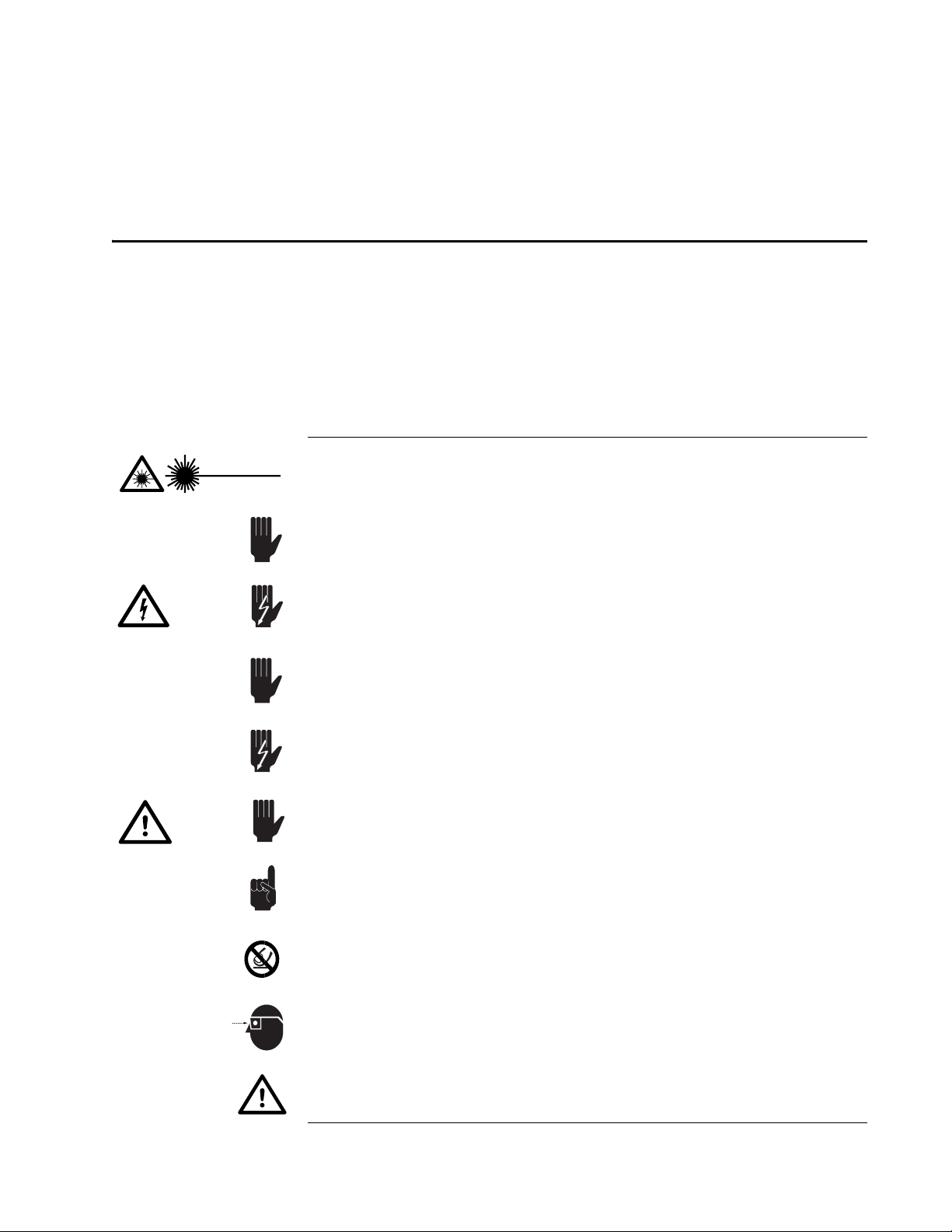
Warning Conventions
The following warnings are used throughout this manual to draw your
attention to situations or procedures that require extra attention. They warn
of hazards to your health, damage to equipment, sensitive procedures, and
exceptional circumstances. All messages are set apart by a thin line above
and below the text as shown here.
Warning!
ESD
Laser radiation is present.
Condition or action may present a hazard to personal safety.
Condition or action may cause damage to equipment.
Condition or action may cause poor performance or error.
Text describes exceptional circumstances or makes a special refer-
ence.
Do not touch.
Appropriate laser safety eyewear should be worn during this opera-
tion.
Danger!
Warning!
Don't
Touch!
Eyewear
Required
Note
Condition or action may present an electrical hazard to personal
safety.
Refer to the manual before operating or using this device.
Action may cause electrostatic discharge and cause damage to equip-
ment.
Danger!
Laser Radiation
Caution!
Danger!


xvii
Standard Units
The following units, abbreviations, and prefixes are used in this Spectra-
Physics manual:
Quantity Unit Abbreviation
mass kilogram kg
length meter m
time second s
frequency hertz Hz
force newton N
energy joule J
power watt W
electric current ampere A
electric charge coulomb C
electric potential volt V
resistance ohm Ω
inductance henry H
magnetic flux weber Wb
magnetic flux density tesla T
luminous intensity candela cd
temperature celcius C
pressure pascal Pa
capacitance farad F
angle radian rad
Prefixes
tera (1012)Tdeci
(10-1)d nano (10-9)n
giga (109)G centi (10-2)cpico
(10-12)p
mega (106)M mill (10-3)mfemto
(10-15)f
kilo (103)kmicro
(10-6)µatto
(10-18)a


xix
Abbreviations
The following is a list of abbreviations used in this manual:
ac alternating current
AOM acousto-optic modulator
APM active pulse mode locking
AR antireflection
bi-fi birefringent filter
CDRH Center of Devices and Radiological Health
CPM colliding pulse mode locking
CW continous wave
dc direct current
E/O electro-optic
fs femtosecond or 10-15 second
GTI Gires-Toutnois Interferometer
GVD group velocity dispersion
HR high reflector
IR infrared
LTC Lok-to-Clock®
OC output coupler
ps picosecond or 10-12 second
PZT piezo-elecric transducer
RF radio frequency
SCFH standard cubic feet per hour
SPM self phase modulation
TEM transverse electromagnetic mode
Ti:sapphire Titanium-doped Sapphire
UV ultraviolet
λwavelength

Table of contents
Popular Industrial Equipment manuals by other brands


PASCOR ATLANTIC
PASCOR ATLANTIC FAS2-V quick start guide

Schleuniger
Schleuniger CrimpCenter 64 SP Original operating manual

Wilo
Wilo Wilo-Yonos ECO BMS Installation and operating instructions

Simpro
Simpro DUMPMASTER DM0700 user manual

Scotchman
Scotchman DO-150-24M manual

kincrome
kincrome KARBON K8112 quick start guide


