Scotchman DO-150-24M User manual
You have downloaded a manual for our
Model DO-150/240-24M Ironworker.
This manual does not include all of the
optional tooling for this machine.
If you would like a tooling manual, please
download our #40 Tooling Manual.
4185
DO NOT EXCEED
3 X 3 X 1/4
WHEN MITERING
0502003195
WARNING
TO PREVENT SERIOUS
BODILY INJURY
DO NOT PLACE FINGERS
BEYOND THIS GUARD
003140
013180
13179
201110
M6x12
201110
M6x12
201110
M6x12
201110
M6x12
013180
13179
201110
M6x12
201110
M6x12
201110
M6x12
201110
M6x12
17341
080435 Assy.
080430
230210230210
13220 - 3ph 13225 - 1ph
230 Volts
19121
OFF
EATON 11856
ELECTRICAL HAZARD
Turn off power
and lock out
before servicing.
DANGER
3122 1213
25525 Raw
224205224205
33176
80155
080174
243101
Assy.
13190
080061
080061
WARNING
SAFETY GLASSES REQUIRED WHEN
OPERATING OR OBSERVING THIS MACHINE
NEVER-
NEVER-
NEVER-
NEVER-
NEVER-
NEVER-
NEVER-
TO PREVENT SERIOUS BODILY INJURY
Operate, install tooling, service or adjust machine without
operator's manual and safety film.
Service machine with electrical power connected.
Operate any station without the respective strippers or
Operate machine with protective guards removed.
Place any part of your body under blade, punch or moving
Operate punch station without checking the punch to die
alignment and tightness.
Punch half holes, punch or shear unknown materials, side load
DO NOT REMOVE THIS SIGN FROM THIS MACHINE
REV. 0310
FOR MORE INFORMATION CONTACT SCOTCHMAN INDUSTRIES INC.
1-800-843-8844
003100
proper instructions and without reading and understanding the
hold-downs in place.
members.
(Check alignment and tightness daily.)
press brakes.
AT
SERIAL
SCOTCHMAN INDUSTRIES, INC.
PHILIP, SOUTH DAKOTA, U.S.A.
MADE IN U.S.A.
MODEL
FLA
HZ
PH
H.P. VOLT
BLADE LENGTH
PH. 605-859-2542
PSI
33149
33156
010117
80191
80211
80197
33018
80424 F
224205224205
224205224205
33157
13268
080174
243101
Assy.
080174
243101
Assy.
80156 Sales
033047
LUBRICATE
BEFORE
OPERATING
19103 0481
LUBRICATE
BEFORE
OPERATING
19103 0481
LUBRICATE
BEFORE
OPERATING
19103 0481
JOG
3200
STOP
START
START
RUN JOG
PUNCH TOOL
RUN PROBE
SHEAR NOTCH
START
MM. IN.
MM. IN.
90
80
70
60
50
40
30
20
10
10
90
80
70
60
50
40
30
20
3
2
1
3
2
1
0
004085
213012
213012
201240
201240
033707
080061
080061
037110
037105
201620
113017
113017
37107 - DO-135 & 150
37003 Assy
#037009 11,04
DUAL OPERATOR
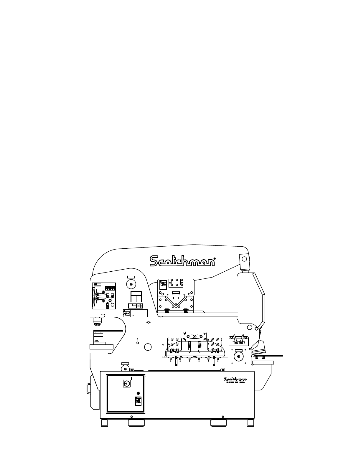
150/240 - 24M
MACHINE CAPACITIES
SPEC. BASED ON MILD STEEL-65,000 PSI TENSILE
PUNCH
150 TONS
Ø47 THRU 25MM
Ø1-7/8 THRU 1.0"
FLAT SHEAR
1 X 14" - 3/4 X 24"
BLADE LENGTH 24" - 600MM
25X300 - 12X600MM
THROAT DEPTH
12" - 305MM
RECT. NOTCHER
76X127X12MM
3"X5"X1/2"
PUNCH STROKE
2.25" - 57MM
ANGLE SHEAR
150X150X12MM
6"X6"X1/2"

www.scotchman.com
MODEL
DO-150/240-24M
IRONWORKER
SCOTCHMAN INDS. - 180 E US HWY 14 - PO BOX 850 - PHILIP, SD 57567 Call: 1-800-843-8844
VERSION 5 - SEPTEMBER 2021
PAGE 2
4185
DO NOT EXCEED
3 X 3 X 1/4
WHEN MITERING
0502003195
WARNING
TO PREVENT SERIOUS
BODILY INJURY
DO NOT PLACE FINGERS
BEYOND THIS GUARD
003140
013180
13179
201110
M6x12
201110M6x12201110M6x12
201110
M6x12
013180
13179
201110
M6x12
201110M6x12201110M6x12
201110
M6x12
17341
080435 Assy.
080430
230210230210
13220 - 3ph 13225 - 1ph
230 Volts
19121
OFF
EATON 11856
ELECTRICAL HAZARD
Turn off power
and lock out
before servicing.
DANGER
3122 1213
25525 Raw
224205224205
33176
80155
080174
243101
Assy.
13190
080061
080061
WARNING
SAFETY GLASSES REQUIRED WHEN
OPERATING OR OBSERVING THIS MACHINE
NEVER-
NEVER-
NEVER-
NEVER-
NEVER-
NEVER-
NEVER-
TO PREVENT SERIOUS BODILY INJURY
Operate, install tooling, service or adjust machine without
operator's manual and safety film.
Service machine with electrical power connected.
Operate any station without the respective strippers or
Operate machine with protective guards removed.
Place any part of your body under blade, punch or moving
Operate punch station without checking the punch to die
alignment and tightness.
Punch half holes, punch or shear unknown materials, side load
DO NOT REMOVE THIS SIGN FROM THIS MACHINE
REV. 0310
FOR MORE INFORMATION CONTACT SCOTCHMAN INDUSTRIES INC.
1-800-843-8844003100
proper instructions and without reading and understanding the
hold-downs in place.
members.
(Check alignment and tightness daily.)
press brakes.
AT
SERIAL
SCOTCHMAN INDUSTRIES, INC.
PHILIP, SOUTH DAKOTA, U.S.A.
MADE IN U.S.A.
MODEL
FLA
HZ
PH
H.P. VOLT
BLADE LENGTH
PH. 605-859-2542
PSI
33149
33156
010117
80191
80211
80197
33018
80424 F
224205224205
224205224205
33157
13268
080174
243101
Assy.
080174
243101
Assy.
80156 Sales
033047
LUBRICATE
BEFORE
OPERATING
19103 0481
LUBRICATE
BEFORE
OPERATING 19103 0481
LUBRICATE
BEFORE
OPERATING
19103 0481
JOG
3200
STOP
START
START
RUN JOG
PUNCH TOOL
RUN PROBE
SHEAR NOTCH
START
MM. IN.
MM. IN.
90
80
70
60
50
40
30
20
10
10
90
80
70
60
50
40
30
20
3
2
1
3
2
1
0
004085
213012
213012
201240
201240
033707
080061
080061
037110
037105
201620
113017
113017
37107 - DO-135 & 150
37003 Assy
#037009 11,04
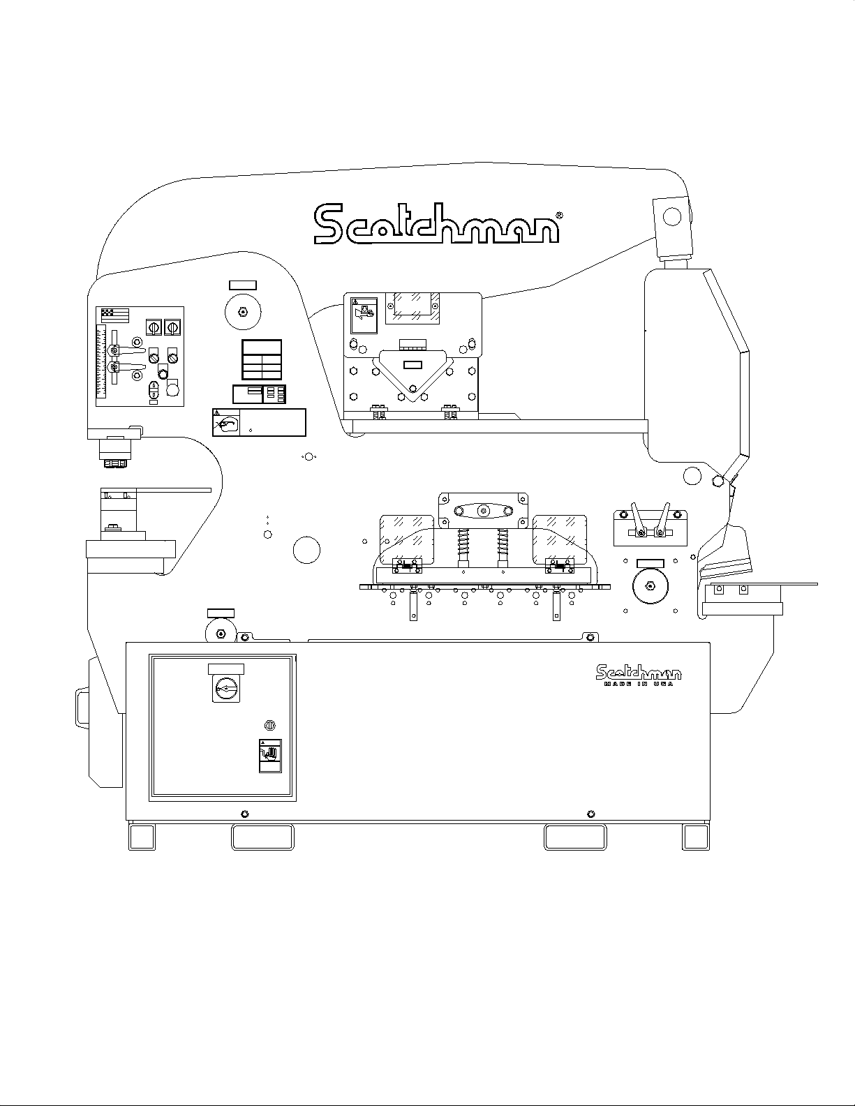
DUAL OPERATOR
150/240 - 24M
MACHINE CAPACITIES
SPEC. BASED ON MILD STEEL-65,000 PSI TENSILE
PUNCH
150 TONS
Ø47 THRU 25MM
Ø1-7/8 THRU 1.0"
FLAT SHEAR
1 X 14" - 3/4 X 24"
BLADE LENGTH 24" - 600MM
25X300 - 12X600MM
THROAT DEPTH
12" - 305MM
RECT. NOTCHER
76X127X12MM
3"X5"X1/2"
PUNCH STROKE
2.25" - 57MM
ANGLE SHEAR
150X150X12MM
6"X6"X1/2"

PAGE 3
SCOTCHMAN INDS. - 180 E US HWY 14 - PO BOX 850 - PHILIP, SD 57567 Call: 1-605-859-2542
TABLE OF CONTENTS
SECTION DESCRIPTION PAGE #
1.0 INTRODUCTION 6
2.1 Warranty 7
SAFETY PRECAUTIONS 62.0
3.0
4.0
4.2
4.3
4.4
MACHINE DECALS
INSTALLATION AND SET UP
Physical Dimensions
Machine Moving Procedures
Physical Inspection
Electrical Requirements
Control Panel Functions
Machine Start Up
Machine Stroke Inspection And Adjustment
Punch & Tool Station
Notch and Shear Station
MAINTENANCE
Lubrication
Scheduled Maintenance
MACHINE OPERATION
Punch Operation
Bar Shear Operation
Shear Arm Adjustment
Shear Blade Adjustment
Rectangle Notcher Operation
Rectangle Notcher Blade Adj. Or Replacement
OPTIONAL TOOLS
6 x 6 Angle Shear
6 x 6 Angle Shear Installation
6 x 6 Angle Shear Operation
Rod Shear
Rod Shear Installation
Rod Shear Operation
4.4A
4.5
4.6
4.6A
4.6B
5.0
5.1
5.2
6.0
6.1
6.2
6.2A
6.2B
6.3
6.3A
7.1
7.1A
7.0
7.1B
7.2
7.2A
7.2B
8
20
18
15
14
12
10
10
30
28
26
26
24
23
22
44
42
42
40
38
36
30
49
49
48
45
45
45
4.1
7.1C 476" A.S. Miter Attachment Assembly

PAGE 4
SCOTCHMAN INDS. - 180 E US HWY 14 - PO BOX 850 - PHILIP, SD 57567 Call: 1-605-859-2542
6 x 6 90° V - Notcher7.3 50
SECTION DESCRIPTION PAGE #
7.5
7.5A
7.5B
12 & 24 Inch Brakes
Brake Installation
Brake Operation
Open End Brake
Open End Brake Installation
Open End Brake Operation
Channel Shear
Channel Shear Installation
Channel Shear Operation
Pipe Notcher
Pipe Notcher Installation
Pipe Notcher Operation
Pipe Notcher Capacities
Picket Fence Tool
Picket Fence Tool Installation
Picket Fence Tool Operation
Square Tube Shear
Square Tube Shear Installation
Square Tube Shear Operation
Optional Die Holders & Punch Retaining Nuts
Offset Die Holder for Flange Punching
2-1/2 x 3 Inch Die Holders
6 x 6 Die Holder
#45 Punch Retaining Nut
Heavy Duty Split-Ring Retaining Nut
48 Inch Back Gauge
Urethane Stripper
Installing The Urethane Stripper, Punch & Die
7.6
7.6A
7.6B
7.7
7.7A
7.7B
7.7C
7.8
7.8A
7.8B
7.9
7.9A
7.9B
7.10
7.10A
7.10B
7.10C
7.10D
7.10E
7.11
7.12
7.12A
58
58
56
56
56
53
52
64
64
63
62
62
62
58
68
68
68
66
66
66
64
74
74
72
70
70
68
7.4B
7.4A
7.4
7.3C
7.3B
7.3A 6 x 6 90° V - Notcher Installation
6 x 6 90° V - Notcher Operation
Blade Replacement
52
52
50
50
This manual suits for next models
1
Table of contents
Other Scotchman Industrial Equipment manuals

Scotchman
Scotchman GAA-500-90 CNC DT20 User manual

Scotchman
Scotchman IRONWORKER 6509-24M User manual

Scotchman
Scotchman GAA-600-90 CNC User manual

Scotchman
Scotchman PRESSPRO 66 User manual

Scotchman
Scotchman 6509-24FF User manual

Scotchman
Scotchman PRESSPRO 176MT User manual

Scotchman
Scotchman CPO-315-RFA-BL User manual


