Watts LF909-FS Use and care manual

RP/IS-LF909S-FS
LF909-QT-S-FS
NOTICE
Use of the integrated flood sensor does not replicate the need to
comply with all required instructions, codes, and regulations related
to installation, operation, and maintenance of this product, including
the need to provide proper drainage in the event of a discharge.
Watts®is not responsible for the failure of alerts due to connectivity or
power issues.
NOTICE
The information contained herein is not intended to replace the full
product installation and safety information available or the experience
of a trained product installer. You are required to thoroughly read all
installation instructions and product safety information before begin-
ning the installation of this product.
Inquire with governing authorities for local installation requirements.
Installation, Maintenance, and Repair Manual
Series LF909-FS Small
Reduced Pressure Zone Assemblies
3⁄4" – 2"
WARNING
!
Read this Manual BEFORE using this equipment.
Failure to read and follow all safety and use information
can result in death, serious personal injury, property
damage, or damage to the equipment.
Keep this Manual for future reference.
Testing
For field testing procedure, refer to Watts®installation sheets
IS-TK-DL, IS-TK-9A, IS-TK-99E and IS-TK-99D at www.watts.com.
For other repair kits and service parts, refer to our Backflow
Prevention Products Repair Kits & Service Parts price list PL-RP-
BPD at www.watts.com.
For technical assistance, contact your local Watts representative.
Series LF909-FS Small is equipped with an integrated flood sensor
that, when activated, triggers notification of potential flood events
from excessive relief valve discharges. An add-on connection is
required to implement sensor activation. A retrofit sensor connection kit
is available for existing installations. See “Add-on and Retrofit Sensor
Connection Kits,” on the last page.
How It Operates
The unique relief valve construction
incorporates two channels: one for
air, the other for water. When the
relief valve opens, the right channel
admits air to the top of the reduced
pressure zone, relieving the zone
vacuum. The left channel then
drains the zone to atmosphere.
(See diagram to the right.) Therefore,
if both check valves foul, and
simultaneous negative supply and
positive backpressure develops, the
relief valve uses the air-in/water-out
principle to stop potential backflow.
Reduced
Pressure
Zone
Water Out Air In
Local building or plumbing codes may require modifications
to the information provided. You are required to consult
the local building and plumbing codes prior to installation.
If this information is not consistent with local building or
plumbing codes, the local codes should be followed. This
product must be installed by a licensed contractor in ac-
cordance with local codes and ordinances.
WARNING
!
WARNING
!
Need for Periodic Inspection/Maintenance: This product
must be tested periodically in compliance with local codes, but
at least once per year or more as service conditions warrant. If
installed on a fire suppression system, all mechanical checks,
such as alarms and backflow preventers, should be flow tested
and inspected in accordance with NFPA 13 and/or NFPA 25.
All products must be retested once maintenance has been
performed. Corrosive water conditions and/or unauthorized
adjustments or repair could render the product ineffective for the
service intended. Regular checking and cleaning of the product’s
internal components helps assure maximum life and proper
product function.
NOTICE
For Australia and New Zealand, line strainers should be installed
between the upstream shutoff valve and the inlet of the backflow
preventer.

• Install backflow preventers in high-visibility locations to allow for
immediate notice of telltale discharge or other malfunction. This
location should also facilitate testing and servicing, and protect
against freezing and vandalism.
• Do not install a backflow preventer in a pit or vault. Ensure that
all local codes and required safety provisions are met. An air
gap below the relief port must be maintained so as to avoid
flooding and submersion of the assembly, which may lead to a
cross-connection.
• Install a strainer ahead of the backflow preventer to protect all
internal components from unnecessary fouling.
Do not install a strainer ahead of the backflow preventer on seldom-
used, emergency water lines (such as fire sprinkler lines). The strainer
mesh could potentially become clogged with debris present in the
water and cause water blockage during an emergency.
• Consider using an air gap and a fabricated indirect waste line to
accommodate normal discharge and nuisance spitting. Floor drains
of the same size must be provided in case of excessive discharge.
• Determine if a check valve is required ahead of the backflow preventer.
When a backflow preventer is installed for dead-end service
applications (such as boiler feed lines, cooling tower makeup, or
other equipment with periodic flow requirements), discharge from
the relief vent may occur due to water supply pressure fluctuation
during static no-flow conditions. *See “Troubleshooting,” before
installation.
• Observe the direction of the flow arrows on the valve assembly.
The backflow preventer is designed so that the critical level of the
relief valve is positioned below the first check. This unique feature
allows the valve to be installed either vertically or horizontally.
• Follow guidelines for the specific installation option selected, that
is, indoor, outside, or parallel. The installation procedure must
comply with all state and local codes.
• Before installation, thoroughly flush all pipelines to remove any
foreign matter.
• At the start-up of initial installation and after servicing, be sure the
downstream shutoff is closed. Slowly open the upstream shutoff
and allow the backflow preventer to fill slowly. Bleed air at each test
cock. When the backflow preventer is filled, slowly open the down-
stream shutoff and fill the water supply system. This is necessary
to avoid dislodging O-rings or causing damage to internal components.
• Have the backflow preventer examined by a certified tester at the
time of installation to ascertain that the assembly is in full working
order and that it can be relied upon to protect the safe drinking
water as per applicable standards.
First
Check
Relief
Valve
Second
Check
LF909-QT-FS
2
Installation Guidelines
CAUTION
!

WattsBox Insulated Enclosures
For more information, download ES-WB.
Min.
12"
ASSE Approved for vertical installation
flow up and down
3
For indoor installations, the valve must be easily accessible
to facilitate testing and servicing. The assembly may be
installed either vertically or horizontally. If it is located in a
line close to wall, be sure the test cocks are easily acces-
sible. A drain line and air gap should be piped from the relief
valve connection as shown, where evidence of discharge
is clearly visible and so that water damage can be limited.
Therefore, never install the assembly in concealed locations.
NOTICE
Test cock must be located on the first or inlet shutoff valve.
For more information on the air gap, download ES-AG/EL/TC
at watts.com.
Flow
Relief Valve
Below First Check
Valve
Air In
Water
Out
Main
▼
Min.
41⁄2"
▼
▼
Air
Gap
First
Check
Valve
LF909QT-S
Vertical Installation - Upward Flow
In an area where freezing conditions do not occur, the assembly
can be installed outside of a building. The most satisfactory installa-
tion is above ground; install in this manner whenever possible.
In an area where freezing conditions can occur, the assembly
should be installed above ground in an insulated enclosure.
The assembly may be installed in a vertical or horizontal line and in
an accessible location to facilitate testing and servicing. A discharge
line should be piped from the air gap at the relief valve connection
making sure there is adequate drainage. Never pipe the discharge
line directly into a drainage ditch, sewer, or sump. The assembly
should never be installed where any part of the unit could become
submerged in standing water. Consideration should be given to the
installation of external support structure as applicable.
In general, the installation of backflow preventers into pits is not rec-
ommended. This type of installation should occur only when abso-
lutely necessary and then only when approved by local codes. In
such cases, a modified pit installation is preferred.
Two or more smaller size valves can be piped in parallel (when
approved) to serve a larger supply pipe main. This type of installa-
tion is employed where increased capacity is needed beyond that pro-
vided by a single valve and permits testing or servicing of an individ-
ual valve without shutting down the complete line.
The number of valves used in parallel should be determined by the
judgment of the compliance engineer based on the operating conditions
of a specific installation.
The following table shows the total capacity provided with dual valve
installations of various sizes.
Indoors
Outside Building Above Ground
Parallel
LF909S
LF909QT-S
Air Gap
(Drawings not to scale)
CAPACITY REQUIRED FOR SYSTEM
50 gpm 100 gpm 150 gpm 200 gpm 250 gpm 350 gpm
Two 3⁄4"Two 1" Two 11⁄4"Two 11⁄2"Two 11⁄2"Two 2"
Devices Devices Devices Devices Devices Devices
NOTICE
Consult local codes for approval.

Complete the following actions before starting the test procedures.
• Ensure all needle valves are closed on the test kit.
• Open test cock No. 4 and flush test cocks No. 1, No. 2, and No. 3 on the reduced pressure
assembly then close test cock No. 4.
• Attach the hoses as shown in the diagram. Bleed air from the kit then close the No. 2 shutoff.
LF909-QT-FS
No. 2 shutoff
Bleed Valve A Bleed Valve B
High
(red)
Bypass
(yellow)
Low
(blue)
Test No. 1 - Check Valve No. 2
Purpose: To test check valve No. 2 for tightness against reverse flow.
Requirements: The valve must be tight against reverse flow under
all pressure differentials.
1. Slowly open the needle valves “A” high (red) and “C”
bypass (yellow). Keep the needle valve “B” low (blue) closed.
2. Open test cock No. 4.
3. Observe that the pressure differential decreases slightly. If the
pressure differential continues to decrease (until the vent opens),
the No. 2 check valve is reported as “leaking.”
Test No. 2 - Shuto Valve No. 2
Purpose: To test shutoff valve No. 2 for tightness.
1. After passing Test No. 1, continue to test No. 2 by closing test
cock No. 2.
2. Observe that the pressure differential decreases slightly. If pressure
differential continues to decrease (approaching “zero”), the No. 2
shutoff valve is reported to be “leaking.”
A leaking No. 2 shutoff always gives a false reading in tests
No. 3 and 4.
Test No. 3 - Check Valve No. 1
Purpose: To test check valve No. 1 for tightness.
Requirements: The valve must be tight against reverse flow under
all pressure differentials.
1. Close needle valve A high (red) and open test cock No. 2.
2. Close test cock No. 4. Disconnect the bypass hose (yellow) at
test cock No. 4.
3. Open needle valves B low (blue) and C bypass (yellow), bleeding
to atmosphere. Then close needle valve B (blue) to restore the
system to a normal static condition.
4. Observe the pressure differential gauge. If there is a decrease in
the indicated value, the No. 1 check valve is reported as “leaking.”
Test No. 4 - Pressure Dierential Relief Valve
Purpose: To test operation of pressure differential relief valve.
Requirements: The pressure differential relief valve must operate to
maintain the “zone” between the two check valves at least 2 psi less
than the supply pressure.
1. Close needle valve C bypass (yellow).
2. Open needle valve A high (red).
3. Open needle valve B low (blue) very slowly until the differential
gauge needle starts to drop.
4. Hold the valve at this position and observe the gauge reading
at the moment the first discharge is noted from the relief valve.
Record this as the opening differential pressure of the relief valve.
The differential gauge needle must drop slowly. This is important
to maintain stability.
5. Close test cocks No. 2 and No. 3. Remove the hoses from test
cocks No. 2 and No. 3.
6. Use the bypass hose (yellow) to relieve pressure from the test
kit by opening needle valves A, B, and C and bleeding valves
A and B.
7. Remove all test equipment and open No. 2 shutoff.
4
CAUTION
!
To prevent freezing, hold the test kit vertically to drain the differential
gauge and hoses before placing the kit in the case.
For additional testing information, refer to IS-TK-DL, IS-TK-9A,
IS-TK-99E, or IS-TK-99D.
Test Procedure for Reduced Pressure Assembly
NOTICE
NOTICE

5
NOTICE
The springs and covers of the first and second check valves are
not interchangeable. The heavier spring loaded module should be
in the first check and the lighter in the second check module.
Cover
Cover
O-ring
Spring
Disc
Assembly
Seat
Seat
O-ring
First Check Second Check
Servicing First and Second Check Valves
First Check
Service Parts Kit
Second Check
Service Parts Kit
Body
Relief Valve
Service Parts Kit
1. Remove the four screws holding the first check valve cover.
2. Lift off the first check valve cover. The check valve comes out
with the cover and is attached with a bayonet type locking
arrangement.
3. Holding the check valve module in both hands, rotate the
assembly quarter turn. This disengages the disc assembly,
spring, and seat cover into individual components.
4. Clean and reassemble the disc assembly or, depending upon its
condition, discard and replace it with a new assembly from the
service kit. O-rings should be cleaned or replaced as necessary
and lightly greased with the FDA Approved silicon grease which
is also furnished with the service kit.
5. Reassemble the check valve module in the reverse order. Service
is identical for both the first and the second check valves.
For further details contact your local technical sales representative.
NOTICE
No special tools are required to service the check valves.

1. Detach the activation module, if installed, from the flood sensor
then remove the sensor from the relief valve.
2. Remove the four bolts that hold the relief valve cover in place.
3. Remove the cover. The stainless steel adapter (or piston) with
O-ring attached is also removed with the cover.
4. Pull out the relief valve assembly.
5. Clean the relief valve seat and disc without disassembling the
relief valve assembly. If the relief valve diaphragm, the disc, or
both need replacement, disassemble the relief valve module. No
special tools are required.
Reassembling the Relief Valve
Much care is required to put the relief valve assembly back together. Follow the instructions closely to prevent any damage to the stem.
CAUTION
!
If the relief valve cover does not press against the body, the assembly is crooked. Tightening the bolts in this instance causes the stem to
bend. Do not force the cover into place; misalignment causes damage.
Figure 1
Have a screwdriver handy to reassemble the
relief valve assembly.
Figure 2
Depress the assembly, carefully guiding it
against the 2 pound spring load. When
properly aligned, the piston is in the cylinder
bore. Insert the screwdriver along the right
channel wall, positioning the screwdriver tip
to the left of the relief valve O-rings to hold
the assembly in place.
Figure 3
Let go of the screwdriver and use both
hands to reattach the cover. Insert two bolts
180 degrees apart and fasten to hold the
cover in place. Insert the two remaining
bolts and fasten by alternating one to the
other until the cover is secure. Remove
the screwdriver. Reattach the flood sensor
to the relief valve and mount the activation
module to the sensor.
Disc Assembly
Piston
O-ring Relief Valve
Assembly
RV O-Ring
Stem
Seat
Body
Cover
Diaphragm
Piston
6
Cover
Seat
O-ring
3⁄4" – 1"
Disc Assembly
(2) Piston
O-rings
Relief Valve
Assembly
(2) RV O-Rings
Stem
Seat
Diaphragm
Piston
Seat
O-ring
11⁄4" – 2"
Servicing the Relief Valve
NOTICE
The spring tension in the relief valve assembly is contained in the
design of the relief valve; therefore, the relief can be removed in a
one-piece spool-type assembly.

7
Problem Cause Solution
Valve spits periodically
from the vent.
Fluctuating supply pressure. Install a soft seated check valve immediately upstream of
the device.
Fluctuating downstream pressure. Install a soft seated check valve downstream of the device,
as close as possible to the shutoff valve.
Valve drips continually
from the vent.
Fouled first check. Flush valve. If flushing does not resolve problem, disassemble
valve and clean or replace the first check.
Damaged or fouled relief valve seat. Clean or replace the relief valve seat.
Relief valve piston O-ring not free to move
due to pipe scale, dirt, or build
up of mineral deposits.
Clean, grease, or replace the piston O-ring.
Excessive back pressure, freezing, or water
hammer has distorted the second check.
Eliminate source of excessive backpressure or water hammer
in the system downstream of the device. Use Watts No. 15
to eliminate water hammer. Replace defective second check
assembly.
In case of freezing, thaw, disassemble, and inspect internal
components.
Replace as necessary.
Electrolysis or relief valve seat or first
check seats.
Replace relief valve seat or inlet cover.
Electrically ground the piping system and/or electrically
isolate the device with plastic pipe immediately upstream
and downstream of the device.
Valve improperly reassembled. If valve is disassembled during installation, exercise caution
when reinstalling check springs in their proper location.
Valve exhibits high
pressure drop.
Fouled strainer. Clean strainer element or replace.
Valve too small for flows encountered. Install proper size device based upon flow requirements.
No water flows down-
stream of valve.
Valve installed backward. Install valve in accordance with flow direction arrow.
Valve does not test properly.Manufacturer’s test procedure not followed. Clean or replace gate valve with full port ball valves or
resilient wedge shutoff valves.
Leaky downstream gate valve.
Valve quickly and repeatedly
fouls following servicing.
Debris in pipeline is too fine to be trapped
by strainer.
Install finer mesh strainer element in the strainer.
Performance of backflow
preventers affected during
winter season.
Cold temperatures. Electric heat-tape wrap closely together around the valve
body. Build a small shelter around the valve with a large
light bulb installed and left on at all times.
If the supply line is not used during the winter, removal of
the complete body is the best. This creates an air gap to
eliminate any possible backflow.
Troubleshooting

RP/IS-LF909S-FS 2250 0834272 © 2022 Watts
Limited Warranty: Watts (the “Company”) warrants each product to be free from defects in material and workmanship under normal usage for a period of one year from the date of original shipment.
In the event of such defects within the warranty period, the Company will, at its option, replace or recondition the product without charge.
THE WARRANTY SET FORTH HEREIN IS GIVEN EXPRESSLY AND IS THE ONLY WARRANTY GIVEN BY THE COMPANY WITH RESPECT TO THE PRODUCT. THE COMPANY MAKES NO OTHER
WARRANTIES, EXPRESS OR IMPLIED. THE COMPANY HEREBY SPECIFICALLY DISCLAIMS ALL OTHER WARRANTIES, EXPRESS OR IMPLIED, INCLUDING BUT NOT LIMITED TO THE IMPLIED
WARRANTIES OF MERCHANTABILITY AND FITNESS FOR A PARTICULAR PURPOSE.
The remedy described in the first paragraph of this warranty shall constitute the sole and exclusive remedy for breach of warranty, and the Company shall not be responsible for any incidental,
special or consequential damages, including without limitation, lost profits or the cost of repairing or replacing other property which is damaged if this product does not work properly, other costs
resulting from labor charges, delays, vandalism, negligence, fouling caused by foreign material, damage from adverse water conditions, chemical, or any other circumstances over which the Company
has no control. This warranty shall be invalidated by any abuse, misuse, misapplication, improper installation or improper maintenance or alteration of the product.
Some States do not allow limitations on how long an implied warranty lasts, and some States do not allow the exclusion or limitation of incidental or consequential damages. Therefore the above
limitations may not apply to you. This Limited Warranty gives you specific legal rights, and you may have other rights that vary from State to State. You should consult applicable state laws to
determine your rights. SO FAR AS IS CONSISTENT WITH APPLICABLE STATE LAW, ANY IMPLIED WARRANTIES THAT MAY NOT BE DISCLAIMED, INCLUDING THE IMPLIED WARRANTIES OF
MERCHANTABILITY AND FITNESS FOR A PARTICULAR PURPOSE, ARE LIMITED IN DURATION TO ONE YEAR FROM THE DATE OF ORIGINAL SHIPMENT.
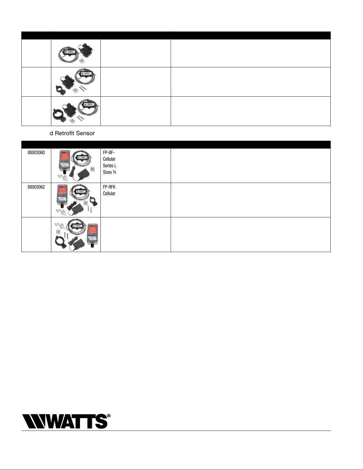
Add-on and Retrofit Sensor Connection Kits for Building Management Systems
ORDERING CODE ADD-ON/RETROFIT KIT DESCRIPTION
88003056 FP-BF-BMS-1/2-2
BMS Sensor Connection Kit
Series LF909-FS Small
Sizes ¾" to 2"
Includes sensor activation module with cable, ground wire, and power adapter. Use this kit to
activate the integrated flood sensor and enable flood detection capabilities on the relief valve
of a new installation working with a BMS controller (not included).
88003058 FP-RFK-BF-BMS-CFS-1-11/2
BMS Sensor Retrofit Connection Kit
Series LF909 Small
Sizes ¾" to 1"
Includes flood sensor, sensor activation module with cable, mounting bolts, ground wire, and
power adapter. Use this kit to install the flood sensor and enable flood detection capabilities
on the relief valve of an existing installation working with a BMS controller (not included).
88003059 FP-RFK-BF-BMS-CFS-2
BMS Sensor Retrofit Connection Kit
Series LF909 Small
Sizes 1¼" to 2"
Includes flood sensor, sensor activation module with cable, mounting bolts, ground wire, and
power adapter. Use this kit to install the flood sensor and enable flood detection capabilities
on the relief valve of an existing installation working with a BMS controller (not included).
Add-on and Retrofit Sensor Connection Kits for Cellular Communication
ORDERING CODE ADD-ON/RETROFIT KIT DESCRIPTION
88003060 FP-BF-CFS-1/2-2
Cellular Sensor Connection Kit
Series LF909-FS Small
Sizes ¾" to 2"
Includes sensor activation module with cable, Cellular Gateway with mounting kit, ground
wire, and power adapter. Use this kit to activate the integrated flood sensor and enable flood
detection capabilities on the relief valve of a new installation working with cellular communication
to send alerts by email message, SMS text message, or voice call.
88003062 FP-RFK-BF-CFS-1-11/2
Cellular Sensor Retrofit Connection Kit
Series LF909 Small
Sizes ¾" to 1"
Includes flood sensor, sensor activation module with cable, Cellular Gateway with mounting
kit, mounting bolts, ground wire, and power adapter. Use this kit to install the flood sensor and
enable flood detection capabilities on the relief valve of an existing installation working with cel-
lular communication to send alerts by email message, SMS text message, or voice call.
88003063 FP-RFK-BF-CFS-2
Cellular Sensor Retrofit Connection Kit
Series LF909 Small
Sizes 1¼" to 2"
Includes flood sensor, sensor activation module with cable, Cellular Gateway with mounting
kit, mounting bolts, ground wire, and power adapter. Use this kit to install the flood sensor and
enable flood detection capabilities on the relief valve of an existing installation working with
cellular communication to send alerts by email message, SMS text message, or voice call.
USA: T: (978) 689-6066 • Watts.com
Canada: T: (888) 208-8927 • Watts.ca
Latin America: T: (52) 55-4122-0138 • Watts.com
This manual suits for next models
2
Table of contents
Other Watts Industrial Equipment manuals

Watts
Watts OneFlow OF210-1 User manual

Watts
Watts FEBCO 880V Series Operating instructions

Watts
Watts LFC500-FS Series Operating instructions

Watts
Watts LF866 Series Operating instructions

Watts
Watts UR.21.S User manual

Watts
Watts FGD Series User manual

Watts
Watts 009 Series Instruction Manual

Watts
Watts AMES Colt C400 Operating instructions

Watts
Watts 919 Series Instruction Manual

Watts
Watts SOLCA BA 4760 User manual