Simpro DUMPMASTER DM0700 User manual
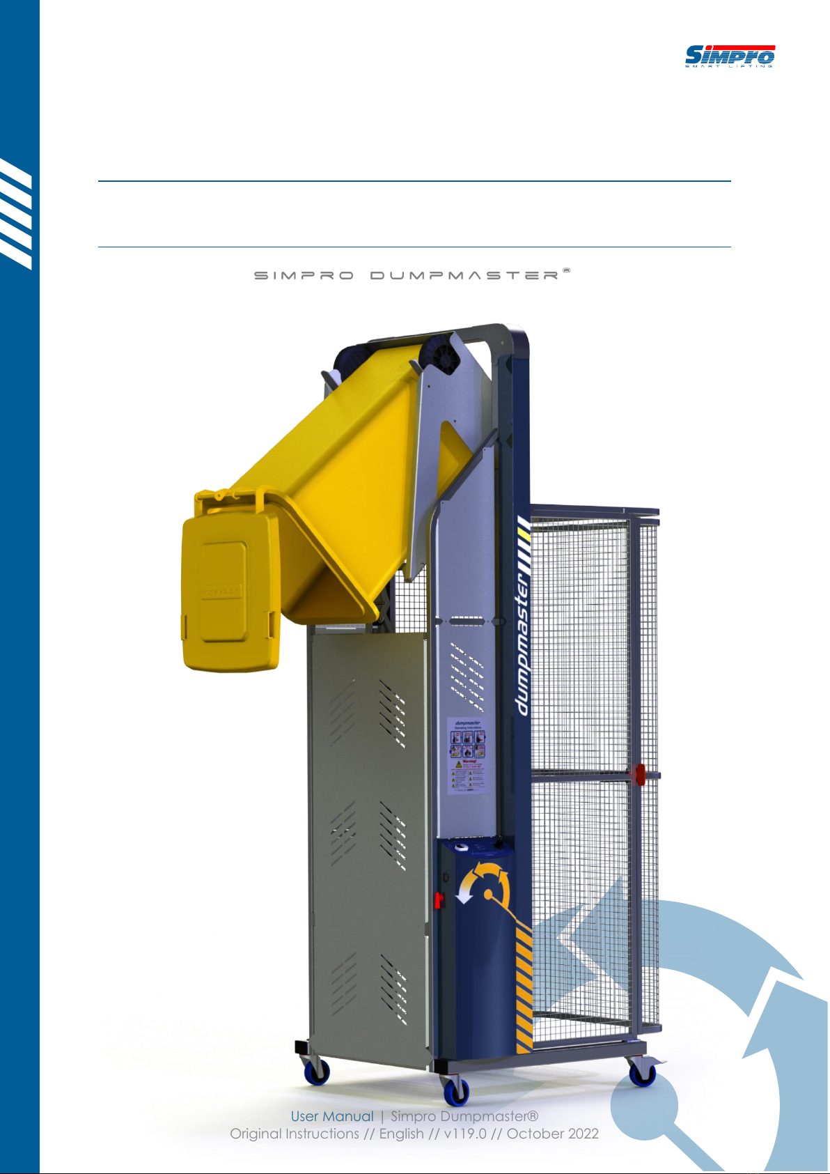
User Manual | Simpro Dumpmaster®
Original Instructions // English // v119.0 // October 2022
USER MANUAL

Copyright © 2022 Simpro Handling Equipment Ltd.
No part of this document may be reproduced or transmitted in any form or by any means,
electronic, mechanical, photocopying, recording, or otherwise, without the written
permission of Simpro Handling Equipment Ltd.
For the purposes of standards compliance and international conformity, this document uses
Système International (SI) units. These may be converted to Imperial units as follows:
1 kilogram (kg) = 2.2 pounds (lb)
1 metre (m) = 1000 millimetres (mm) = 39.37 inches (in) = 3.28 feet (ft) = 1.09 yards (yd)
The following stylistic conventions are used throughout this document:
Point of interest
Safety hazard
§ Section reference (hyperlink in PDF edition)
Simpro partcode (hyperlink in PDF edition)
User Manual // Simpro Dumpmaster®
Original Instructions // English // v119.0 // October 2022 // Page 2
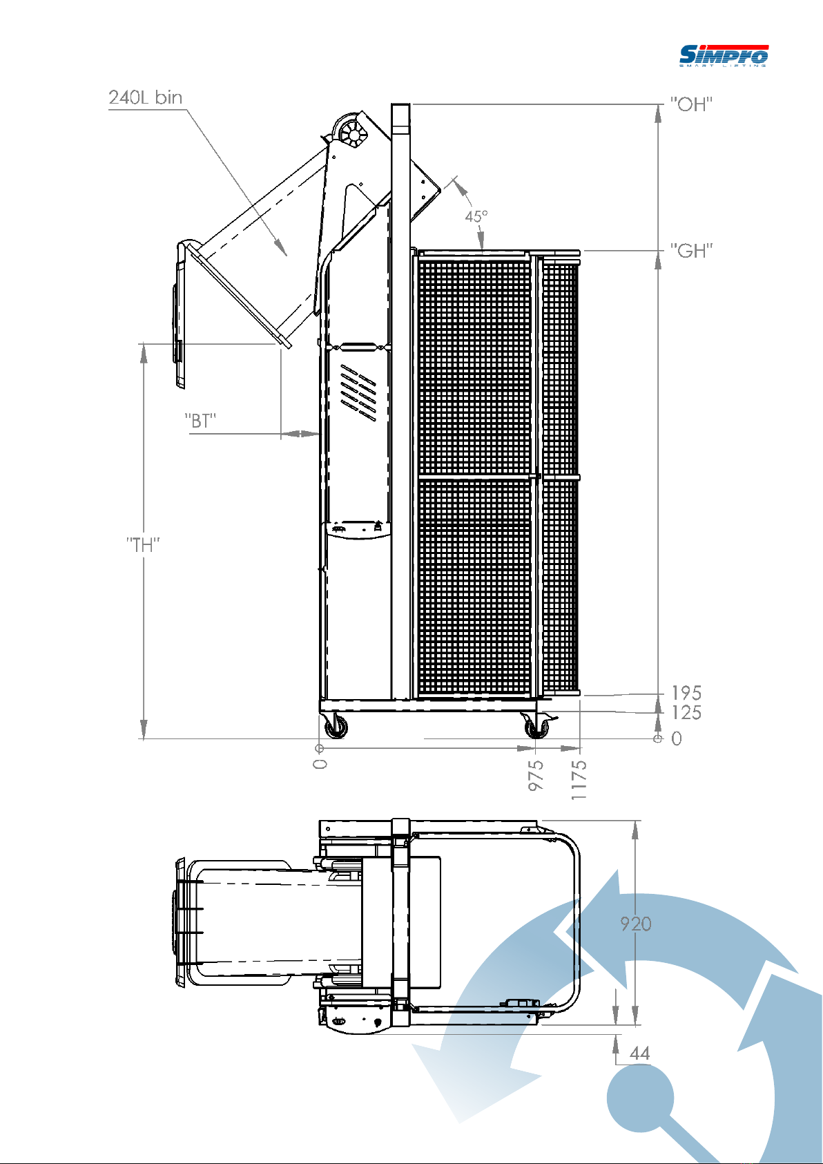
Generic Dumpmaster layout and dimensions

Contents
1. Product Overview ......................................................................................................................... 5
1.1 Key features ......................................................................................................................................... 5
1.2 Construction ........................................................................................................................................ 5
1.3 Mechanism .......................................................................................................................................... 6
1.4 Safe Working Load .............................................................................................................................. 6
1.5 Duty cycle ............................................................................................................................................ 6
1.6 Service life ............................................................................................................................................ 7
1.7 Noise emissions .................................................................................................................................... 7
1.8 Environmental restrictions ................................................................................................................... 7
1.9 Ingress protection................................................................................................................................ 7
1.10 Notes..................................................................................................................................................... 8
2. Operating Instructions ..................................................................................................................9
2.1 Before operation ................................................................................................................................. 9
2.2 Emplacing and removing bins........................................................................................................... 9
2.2.1 Cradle identification ........................................................................................................................................9
2.2.2 Type-E Cradle ................................................................................................................................................. 11
2.2.3 Type-C Cradle ................................................................................................................................................11
2.2.4 Type-A Cradle ................................................................................................................................................11
2.2.5 Type-A Cradle with base ...............................................................................................................................12
2.2.6 Type-D Cradle ................................................................................................................................................12
2.2.7 Type-X Custom Cradle.................................................................................................................................. 12
2.3 Operation of controls........................................................................................................................ 13
2.3.1 Control Panel identification...........................................................................................................................13
2.3.2 Standard Control Panel ................................................................................................................................. 14
2.3.3 Autocycle Control Panel ...............................................................................................................................14
2.3.4 VSD Control Panel.......................................................................................................................................... 15
2.3.5 Safety-Monitored Control Panel ................................................................................................................... 15
2.4 Safety Norms...................................................................................................................................... 17
3. Care and Maintenance............................................................................................................. 19
3.1 Quick Troubleshooting Guide .......................................................................................................... 19
3.2 Cleaning............................................................................................................................................. 20
3.3 Cradle jams........................................................................................................................................ 20
3.3.1 Cradle jams while raising ............................................................................................................................... 20
3.3.2 Cradle jams while lowering ...........................................................................................................................21
3.4 Electrical System (battery)................................................................................................................ 23
3.4.1 International conformance...........................................................................................................................23
3.4.2 Voltmeter ........................................................................................................................................................ 23
3.4.3 Battery charging ............................................................................................................................................23
3.4.4 Batteries .......................................................................................................................................................... 24
3.4.5 Battery charger ..............................................................................................................................................24
3.4.6 Appliance inlet ............................................................................................................................................... 24
3.4.7 Isolator switch .................................................................................................................................................24

User Manual // Simpro Dumpmaster®
Original Instructions // English // v119.0 // October 2022 // Page 4
3.4.8 Circuit breaker................................................................................................................................................24
3.4.9 Solar panel...................................................................................................................................................... 25
3.5 Electrical System (3-phase mains) ................................................................................................... 26
3.5.1 International conformance...........................................................................................................................26
3.5.2 Appliance inlet ............................................................................................................................................... 26
3.5.3 Isolator switch .................................................................................................................................................26
3.5.4 Transformer .....................................................................................................................................................26
3.6 Electrical System (1-phase mains) ................................................................................................... 27
3.6.1 International conformance...........................................................................................................................27
3.6.2 Appliance inlet ............................................................................................................................................... 27
3.6.3 Isolator switch .................................................................................................................................................27
3.6.4 Transformer .....................................................................................................................................................27
3.6.5 Variable Speed Drive..................................................................................................................................... 27
3.7 Hydraulic System ............................................................................................................................... 28
3.7.1 Powerpack ..................................................................................................................................................... 28
3.7.2 Control valves................................................................................................................................................. 28
3.7.3 Lift ram.............................................................................................................................................................28
3.7.4 Hydraulic fluid................................................................................................................................................. 28
3.7.5 Maintenance.................................................................................................................................................. 29
3.7.6 Hydraulic system schematic.......................................................................................................................... 29
3.8 Safety door and interlock................................................................................................................. 30
3.8.1 Side-hinge safety door (standard) ............................................................................................................... 30
3.8.2 Swing-up safety door (custom)..................................................................................................................... 30
3.8.3 Safety door interlock......................................................................................................................................30
3.9 Safety-Monitoring System (CAT3/CAT4 only).................................................................................. 33
3.9.1 440C-CR30 Safety Relay ................................................................................................................................ 33
3.9.2 Troubleshooting ..............................................................................................................................................34
3.9.3 Configuration .................................................................................................................................................34
3.10 Preventative Maintenance Inspections.......................................................................................... 35
3.10.1 Pre-inspection checklist ............................................................................................................................35
3.10.2 Weekly inspection ..................................................................................................................................... 35
3.10.3 Monthly inspection .................................................................................................................................... 37
3.10.4 Annual inspection ..................................................................................................................................... 39
4. Assembly, Handling and Storage.............................................................................................. 41
5. Safety Assessment ....................................................................................................................... 43
5.1 Safety features................................................................................................................................... 43
5.2 Reasonably foreseeable misuse ...................................................................................................... 43
5.3 Hazard and Risk Assessment Guide................................................................................................. 43
5.4 OSH Compliance Specification Guide ........................................................................................... 48
6. Spare Parts ................................................................................................................................... 51
7. Warranty....................................................................................................................................... 53
8. EC Declaration of Conformity ...................................................................................................55
9. Notes............................................................................................................................................. 56

1. Product Overview
Congratulations on your purchase of a Simpro Dumpmaster bin-tipping machine.
Dumpmaster is probably the safest and most reliable bin tipper on the market, having been
in continuous production for more than thirty years.
Dumpmaster is very versatile and can be used in numerous applications, ranging from
emptying rubbish bins into skips to pouring food ingredients into mixers. Regardless of the
application, Dumpmaster has proven to be safe, reliable, and
economical to operate, year after year.
1.1 Key features
Key features of the Dumpmaster include:
1. A unique tipping action
whereby bins are lifted
straight up, and then gently
rolled forward around the lip
of the skip or hopper being
emptied into. Benefits of this
design include a small
‘footprint’, and a wide range
of tipping heights available, from
700mm to more than six metres.
2. A standard weight capacity of 250kg.
3. A very reliable, maintenance-free design.
4. A fully hot-dip galvanised frame and cradle
as standard (with options for full or partial
stainless steel for hygiene-critical areas).
5. A standard cradle which lifts almost all
EN840 wheelie bins without clamping or
retaining.
6. A modular design which can be easily modified to suit a wide range of non-standard
bin sizes, shapes, and weights.
1.2 Construction
The Dumpmaster consists of a steel frame with vertical masts and stabilizing legs, bin cradle,
hydraulic ram, hydraulic powerpack, powerpack cover, control panel, electronic control
systems, guarding, castor wheels, and power lead or charging cable.

User Manual // Simpro Dumpmaster®
Original Instructions // English // v119.0 // October 2022 // Page 6
1.3 Mechanism
When the RAISE button is pressed, a hydraulic ram is extended, which pulls on an
arrangement of chains, causing the bin cradle to travel vertically in the masts. The cradle is
inverted at the appropriate height by an arrangement of arms, rollers, and a curved track.
The ram is supplied by a hydraulic power pack, which may have a 3-phase, 1-phase, battery,
or compressed-air motor. Electrical, hydraulic, and / or mechanical control mechanisms
allow the operator to raise or lower the bin in a controlled manner.
1.4 Safe Working Load
The Safe Lifting Capacity of the standard Dumpmaster is 250kg (550lb).
Safe Working Load (SWL) is a gross figure, referring to the weight of the bin, its contents,
and any other objects placed on the cradle.
Custom machines may be specified with different Safe Working Loads. The rating plate
should be the first point of reference to determine SWL on any given machine.
Never attempt to lift bins that are heavier than the factory-specified Safe Working Load.
1.5 Duty cycle
The duty cycle of the Dumpmaster depends on the type of power supply and powerpack
that is fitted to the machine, as well as various environmental factors and the manner in
which the machine is used. The figures given below are estimates only.
Power supply
Duty Cycle (tipping ~100kg bins at 1800mm)
Net throughput
Number of bins
Units
24V/20Ah Gel Battery*
10,000kg
100 bins
Per charge
24V/20Ah Gel Battery* with
continuous charge
3,000kg
30 bins
Per hour
24V/20Ah Gel Battery* with
solar panel kit
3,000kg
30 bins
Per day**
Mains, 3-Phase ~415VAC
6,000kg
60 bins
Per hour
Mains, 1-Phase ~230VAC***
4,000kg
40 bins
Per hour
*2x 12V/20Ah batteries in series; default from 2015 **Subject to weather, latitude, and panel orientation; see §3.4.9 ***Deprecated since 2019
Power supply specifications can be found on the machine’s rating plate.

1.6 Service life
The nominal service life of the Dumpmaster is as follows:
Average Gross Bin Weight
Nominal service life
< 100kg
200,000 cycles
100kg –200kg
150,000 cycles
200kg –250kg
100,000 cycles
250kg –300kg
75,000 cycles
> 300kg
50,000 cycles
1.7 Noise emissions
The noise emissions of the Dumpmaster do not typically exceed ~60 dB(A) at the operator’s
ear. Hearing protection is recommended if operating the machine for extended periods.
ISO standards for machinery safety specify that noise emissions are to be measured in A-
weighted decibels (dB(A)), a unit of volume which is adjusted to reflect the sensitivity of
human hearing. The measurements are taken at a point 1.6 metres above the ground at
the operator’s working position.
1.8 Environmental restrictions
The Dumpmaster may be used indoors or outdoors. However, the following restrictions apply:
1. Minimum floor area 2 square metres, with a clear passage to exits;
2. Height above sea level not more than 1000m;
3. Ambient temperature not higher than +40℃and not lower than -10℃;
4. At ambient temperatures above 35℃, the relative humidity should not exceed 50%; at
lower temperatures, higher relative humidity is permitted;
Never operate the Dumpmaster in explosive, corrosive, acidic or alkaline environments.
1.9 Ingress protection
Item
IP Rating
Push buttons, switches, and lamps
IP66
Door interlock
IP66
Coded magnetic switch
IP66
Motor
IP54 (additional protection is provided by covers)
Overall
IP56 (optionally upgraded to IP66 or IP69)

User Manual // Simpro Dumpmaster®
Original Instructions // English // v119.0 // October 2022 // Page 8
1.10 Notes
1. This User Manual describes approved procedures for the operation, maintenance,
and routine inspection of the Simpro Dumpmaster hydraulic bin-tipping machine.
2. This manual is written in English, and is to be considered the ‘Original Instructions’ for
the purposes of EU Machinery Directive 2006/42/EC.
3. Operator(s) must read and understand this manual before using the machine.
4. If the machine is to be leased, sold, or otherwise transferred, then this manual shall
accompany the machine.
5. This is a generic manual. Simpro reserves the right to change the design of our
products at any time. In cases where a discrepancy exists between the manual and
the actual product, the manual is to be used as a reference only.
6. Contact your authorized Simpro agent if any problems or faults are encountered with
the machine.
7. Errors in this manual should be reported by email to i[email protected].

2.Operating Instructio ns
Before the machine is used for the first time, a site-specific Hazard and Risk Assessment
should be completed as per §5.3.
2.1 Before operation
Before operating a Dumpmaster, check the following points to ensure that the machine is
stable and safe to use:
1. The machine is on firm ground, with a slope ratio less than 1:12.
2. All covers and safety guards are in place.
3. The wheel brakes are applied, and/or the feet are wound down onto the ground.
4. All personnel other than the operator are well clear of the machine.
5. The cradle is fully lowered.
6. The key is inserted and turned to the ON position.
7. The battery indicator (if fitted) shows an acceptable level of charge.
2.2 Emplacing and removing bins
The Dumpmaster cradle is designed to allow bins to be emplaced and removed easily, while
also holding them securely throughout the tipping cycle.
It is important to understand how to correctly place bins onto the cradle, as improper
placement may result in bins falling out of the machine when inverted.
2.2.1 Cradle identification
A range of different cradles may be fitted to the Dumpmaster, depending on the bins it will
be emptying. Use the following table to identify the correct instructions for your machine.
Cradle Type
Primary Usage
Bin Compatibility
Cradle Image
Refer
Type-E
(EN840
base-lift
cradle)
General waste
and recycling
applications
EN840 mobile
garbage bins
(wheelie bins)
-60L
-80L
-120L
-140L
-240L
§2.2.2

User Manual // Simpro Dumpmaster®
Original Instructions // English // v119.0 // October 2022 // Page 10
Cradle Type
Primary Usage
Bin Compatibility
Cradle Image
Refer
Type-C
(EN840
comb-lift
cradle)
Specialised
waste and
recycling
applications
(primarily with
360-litre bins)
-60L
-80L
-120L
-140L
-240L
-360L
§2.2.3
Type-A
(ANSI bar-lift
cradle)
General waste
and recycling
applications in
North America
ANSI Z245.60
(Type-B) Trash
Carts
-32 gal
-48 gal
-64 gal
-96 gal
§2.2.4
Type-A with
base
(ANSI bar-lift
cradle with
base)
Specialised
waste and
recycling
applications in
North America
BRUTE® Bins
205L Drums
Plastic Tubs
Customs Bins
-10 gal
-20 gal
-28 gal
-32 gal
-40 gal
-44 gal
-55 gal
§2.2.5
Type-D
(DIN9797)
Food processing
applications
DIN9797
Eurobins
-120L
-200L
-300L
§2.2.6
Type-X
(Custom)
Custom
applications
BRUTE® Bins
205L Drums
Plastic Tubs
Customs Bins
§2.2.7

2.2.2 Type-E Cradle
2.2.2.1 Emplacing bins
Open the door and place the wheelie bin onto the cradle. For
full-size 240L bins, both wheels should be positioned into a catch
(on either side of the cradle). For smaller bins such as 60L, 80L,
120L and 140L, only the left-hand wheel needs be positioned into
a catch. Once the bin is correctly emplaced, close the door.
The wheel catches are designed to work with standard EN840
wheelie bins from leading brands such as Europlast, Sulo, ESE,
Weber, Craemer, OnePlastics and Trident.
Some smaller bin manufacturers use axles of different lengths. If the distance between
the wheels is slightly too large or small, the wheels may jam against the catches,
preventing a secure emplacement. Should this occur, simply unbolt and remove the
right-hand wheel catch. All bins can be securely retained using the left-hand catch only.
Some smaller bin manufacturers use tyres which are too wide to fit inside the wheel
catches. Should this issue occur, simply insert additional packers (flat washers) onto the
wheel catch mounting bolts, to increase the spacing as needed.
2.2.2.2 Removing bins
Open the door and, using the grab-handle provided, remove the
wheelie bin from the cradle.
2.2.3 Type-C Cradle
2.2.3.1 Emplacing bins
Open the door and place the wheelie bin into the machine, positioned
centrally against the cradle backplate. Take care that the lifting teeth
are properly hooked into the bin combing; smaller bins such as 60L
and 80L may need to be tilted or lifted slightly to ensure a proper
‘catch’. Once the bin is correctly emplaced, close the door.
2.2.3.2 Removing bins
Open the door and, using the grab-handle provided, remove the wheelie bin from the
cradle. The bin may need to be tilted slightly to disengage the comb from the cradle ‘teeth’.
2.2.4 Type-A Cradle
2.2.4.1 Emplacing bins
Open the door and place the trash cart into the machine, positioned
centrally against the cradle backplate. Take care that the lifting
catches are properly hooked into the front of the cart; some carts may
need to be tilted or shaken slightly to ensure a proper ‘catch’. Once
the cart is correctly emplaced, close the door.
2.2.4.2 Removing bins
Open the door and, using the grab-handles provided, remove the
trash cart from the cradle. Some carts may need to be tilted or shaken
slightly to detach them from the lifting catches.

User Manual // Simpro Dumpmaster®
Original Instructions // English // v119.0 // October 2022 // Page 12
2.2.5 Type-A Cradle with base
2.2.5.1 Emplacing bins
Open the door and place the bin, drum, or container onto the cradle,
positioned centrally against the backplate. Once the bin is correctly
emplaced, close the door.
When moving heavy non-wheeled containers, it is
recommended to use a dolly, hand truck or forklift attachment.
The catch arm(s) should be positioned to hold the top edges
of the bin, with a maximum free travel of 25mm (1 inch). The
arm(s) can be unbolted and repositioned to allow emptying
bins of many different sizes.
2.2.5.2 Removing bins
Open the door and, holding the upper lip of the bin, drum, or container, remove it from the
cradle.
2.2.6 Type-D Cradle
2.2.6.1 Emplacing bins
Open the door and wheel the Eurobin into the cradle,
positioned centrally, until it is firmly against the stop-buffers.
Take care that both trunnions are properly seated in the lifting
arms; some Eurobins may need to be tilted or shaken slightly to
ensure a proper ‘catch’. Once the Eurobin is correctly
emplaced, close the door.
2.2.6.2 Removing bins
Open the door and, using the grab-handle provided, remove the Eurobin from the cradle.
2.2.7 Type-X Custom Cradle
2.2.7.1 Emplacing bins
Open the door and place the bin, drum, or container onto the
cradle, positioned centrally against the backplate. Once the bin is
correctly emplaced, close the door.
When moving heavy non-wheeled containers, it is
recommended to use a dolly, hand truck or forklift attachment.
The catch arm(s) should be positioned to hold the top edges
of the bin, with a maximum free travel of 25mm (1 inch). The
arm(s) can be unbolted and repositioned to allow emptying
bins of many different sizes.
2.2.7.2 Removing bins
Open the door, and holding the upper lip of the bin, drum, or container, remove it from the
cradle.

2.3 Operation of controls
The Dumpmaster controls are designed to allow safe, intuitive operation of the machine.
It is important to understand how to use the controls correctly. Improper operation may
result in a safety hazard, or damage to the machine.
2.3.1 Control Panel identification
The Dumpmaster may be fitted with a variety of different controls, depending on the
operational and safety requirements of the machine. Use the following table to identify the
correct operating instructions for your machine.
The control panel is normally atop the powerpack cover, but on custom models it may
be mounted on a separate electronics enclosure.
Control
Panel Type
Primary Usage
Controls
Image
Refer
Standard
Standard
machines
-RAISE/LOWER
-KEY SWITCH
-VOLTMETER (battery
machines only)
§2.3.2
Autocycle
Machines with an
autocycle
controller
-RAISE/LOWER
-EMERGENCY STOP
-CONTROL MODE
(AUTO/MANUAL)
§2.3.3
VSD
Machines with a
Variable Speed
Drive controller
-JOYSTICK FOR
RAISE/LOWER
-KEY SWITCH
§2.3.4
Safety-
Monitored
Machines with
safety-monitoring
systems to comply
with 13849-1:2015
and AS/NZS4024
up to CAT3/CAT4
-RAISE/LOWER
-EMERGENCY STOP
-CONTROL MODE
(AUTO/MANUAL)
-SAFETY RESET
-Panel describing
the architecture of
the safety-
monitoring systems
(CAT3/CAT4)
Example Only
§2.3.5
User Manual // Simpro Dumpmaster®
Original Instructions // English // v119.0 // October 2022 // Page 14
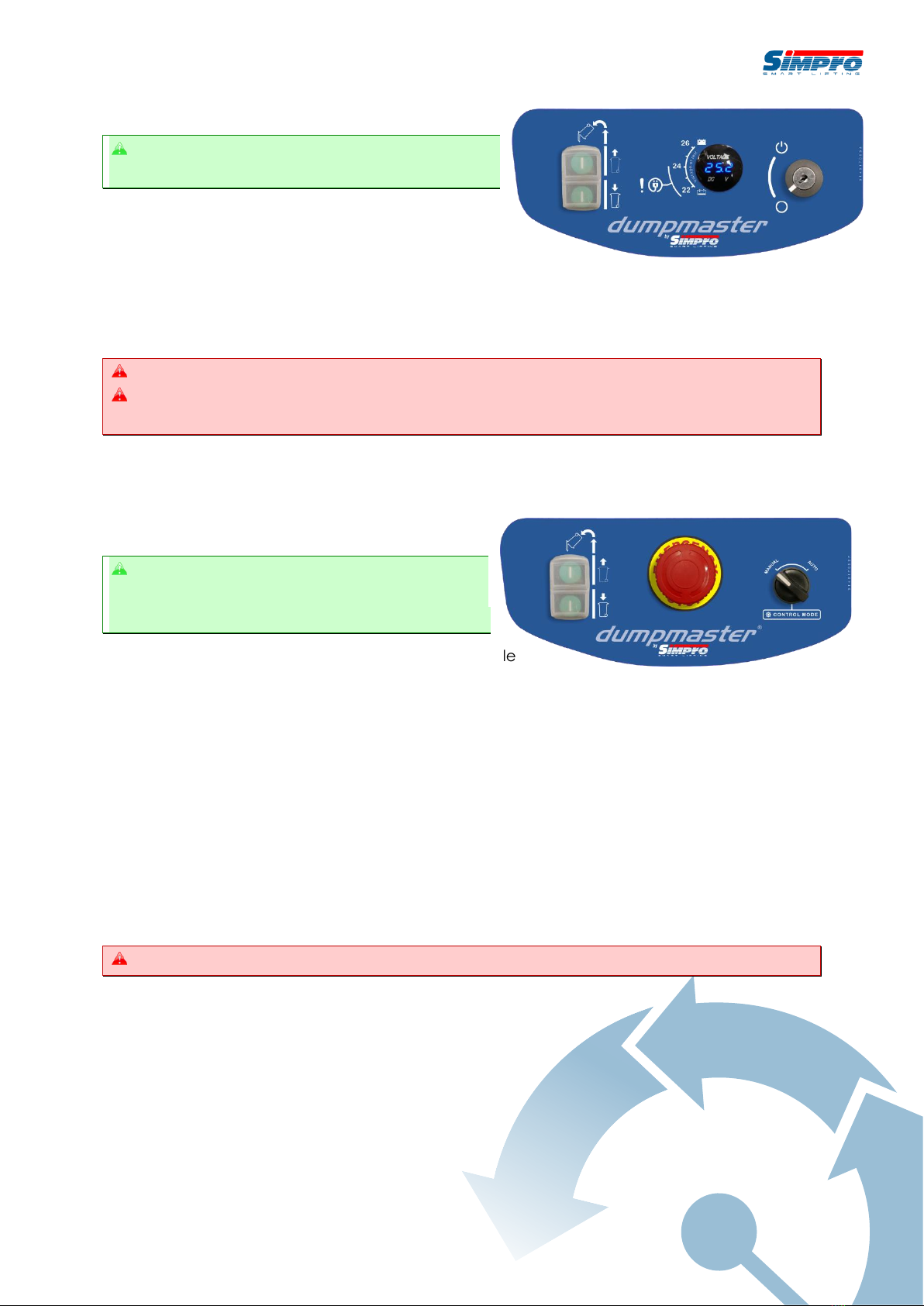
2.3.2 Standard Control Panel
How to operate the controls of a standard
machine, with no PLC or autocycle controller.
1. Before operation, check that the machine is
stable and safe to use as per §2.1.
2. Open the door and place the full bin onto the cradle,
taking care that it is properly positioned as per §2.2, then shut the door.
3. Press and hold the RAISE button until the bin reaches the inverted position, then
release. Wait for the contents of the bin to empty.
Release the RAISE/LOWER button to stop the cradle at any time.
Do not continue pressing the RAISE button after the cradle has reached the top of the
cycle, as this can overheat the hydraulic fluid and cause premature wear on the motor.
4. Press and hold the LOWER button until the cradle rests on the ground.
5. Open the door and remove the empty bin as per §2.2.
6. Repeat from step 2. as required.
2.3.3 Autocycle Control Panel
How to operate the controls of a machine
with an autocycle controller, allowing bins to
be emptied without continuous input.
Dumpmaster models that are fitted with an autocycle
control system may be used in either MANUAL or AUTO mode, selected using a switch on the
control panel.
The operating procedure for each mode is as follows:
2.3.3.1 AUTO mode
1. Before operation, check that the machine is stable and safe to use as per §2.1.
2. Open the door and place the full bin onto the cradle, taking care that it is properly
positioned as per §2.2, then shut the door.
3. Turn the mode-selector switch to AUTO.
4. Press the RAISE button once. The cradle will automatically lift, hold the bin inverted for
a short time, and return to ground level.
Press the EMERGENCY STOP button to stop the cradle at any time.
5. Open the door and remove the empty bin as per §2.2.
6. Repeat from step 2. as required.
2.3.3.2 MANUAL mode
1. Before operation, check that the machine is stable and safe to use as per §2.1.
2. Open the door and place the full bin onto the cradle, taking care that it is properly
positioned as per §2.2, then shut the door.
3. Turn the mode-selector switch to MANUAL.
4. Press and hold the RAISE button until the bin reaches the inverted position, then
release. Wait for the contents of the bin to empty.
Release the RAISE/LOWER button or press the EMERGENCY STOP button to stop the cradle
at any time.
5. Press and hold the LOWER button until the cradle returns to the ground.
6. Open the door and remove the empty bin as per §2.2.
7. Repeat from step 2. as required.
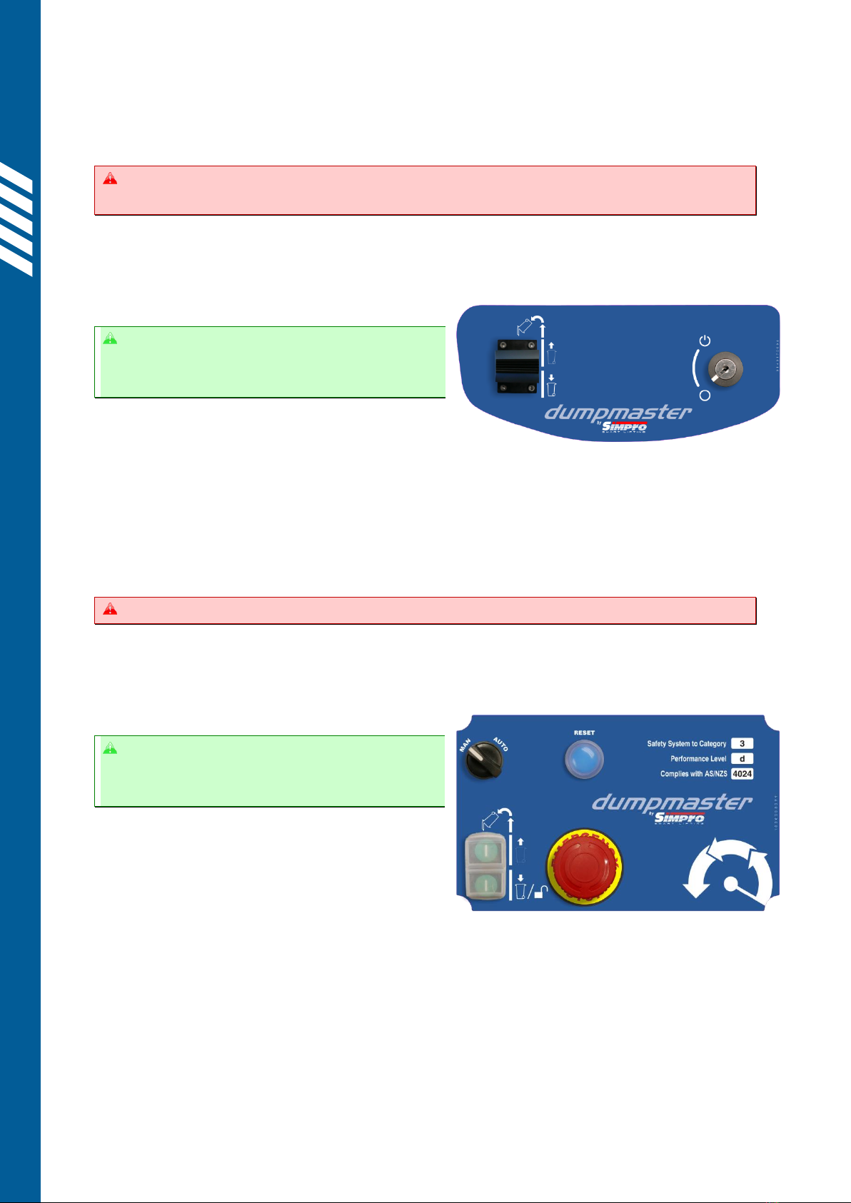
2.3.4 VSD Control Panel
How to operate the controls of a VSD
machine, with a joystick to allow progressive
control of the lifting speed.
1. Before operation, check that the machine
is stable and safe to use as per §2.1.
2. Open the door and place the full bin onto the cradle, taking care that it is properly
positioned as per §2.2, then shut the door.
3. Push the JOYSTICK FULLY FORWARD to begin lifting the bin.
4. When the bin reaches the top of the mast and starts to invert, gently move the
JOYSTICK SLIGHTLY BACK so that the material is poured from the bin in a controlled
manner, as desired. Wait for the contents of the bin to empty.
Release the JOYSTICK to stop the cradle at any time.
5. Pull the JOYSTICK FULLY BACK until the cradle rests on the ground.
6. Open the door and remove the empty bin as per §2.2.
7. Repeat from step 2. as required.
2.3.5 Safety-Monitored Control Panel
How to operate a machine with a safety-
rated PLC control unit and CAT3/CAT4
monitoring system.
Dumpmaster models that are fitted with a safety-
monitored control system may be used in either
MANUAL or AUTO mode, selected using a switch
on the control panel.
The operating procedure for each mode is as follows:
2.3.5.1 AUTO mode
1. Before operation, check that the machine is stable and safe to use as per §2.1.
2. Open the door. If the door is locked, press the LOWER button to unlock it.
3. Place the full bin onto the cradle, taking care that it is properly positioned as per §2.2,
then shut the door.
4. Turn the mode-selector switch to AUTO.
5. Press and hold the blue SAFE MODE RESET button for two seconds.

User Manual // Simpro Dumpmaster®
Original Instructions // English // v119.0 // October 2022 // Page 16
a. The safety system will now conduct an auto-diagnostic check. If no faults are
detected, the blue light will go out and the system will enter READY MODE.
b. If a fault is detected, the blue light will not go out and the system will remain in
SAFE MODE. The fault must be found and corrected before the machine can
be used, as per §3.9.
6. Press the RAISE button once. The cradle will automatically lift, hold the bin inverted for
a short time, then return to ground level.
Press the EMERGENCY STOP button to stop the cradle at any time.
7. Open the door and remove the empty bin as per §2.2.
8. Repeat from step 2. as required.
Once the cradle has lowered, the door is automatically unlocked for about 15 seconds. If
the door re-locks, press the LOWER button to unlock it at any time.
2.3.5.2 MANUAL mode
1. Before operation, check that the machine is stable and safe to use as per §2.1.
2. Open the door. If the door is locked, press the LOWER button to unlock it.
3. Place the full bin onto the cradle, taking care that it is properly positioned as per §2.2,
then shut the door.
4. Turn the mode-selector switch to MANUAL.
5. Press and hold the blue SAFE MODE RESET button for two seconds.
a. The safety system will now conduct an auto-diagnostic check. If no faults are
detected, the blue light will go out and the system will enter READY MODE.
b. If a fault is detected, the blue light will not go out and the system will remain in
SAFE MODE. The fault must be found and corrected before the machine can
be used, as per §3.9.
6. Press and hold the RAISE button until the bin reaches the inverted position, then
release. Wait for the contents of the bin to empty.
Release the RAISE/LOWER button or press the EMERGENCY STOP button to stop the cradle
at any time.
7. Press and hold the LOWER button until the cradle rests on the ground.
8. Open the door and remove the empty bin as per §2.2.
9. Repeat from step 2. as required.
Once the cradle has lowered, the door is automatically unlocked for about 15 seconds. If
the door re-locks, press the LOWER button to unlock it at any time.

2.4 Safety Norms
The following safety norms must be observed for the safe use of a Dumpmaster bin lifter.
Only trained and authorised personnel may use the
machine.
Operators must read and obey all instructions
displayed on the machine.
Never operate the machine on soft ground, or
ground with a slope ratio greater than 1:12.
Never operate machine on the edge of a raised dock
or platform, unless designed for that application.
Never operate the machine with any covers or
guards removed.
Never attempt to empty the contents of closed-top
drums, unless the machine is securely bolted down.
All persons other than the operator must keep at
least two metres clear while the machine is in use.
Always keep hands and feet well clear of the bin and
cradle when operating.
Never place limbs, feet or foreign objects under the
side guards or safety door.
Never attempt to empty over-filled bins, or bins that
weigh more than the machine's rated capacity.

User Manual // Simpro Dumpmaster®
Original Instructions // English // v119.0 // October 2022 // Page 18
Before connecting machine to mains supply,
ensure voltage and frequency correspond with
that listed on the rating plate.
Do not use an extension lead longer than 15
metres to connect the machine to mains power.
Do not operate if power lead, insulation or power
plugs are damaged.
Do not connect a damp power plug or socket.
Ensure the power supply socket is fitted with a
residual current device.
Ensure there is complete continuity between the
machine and an effective earthing system which
complies with local and national regulations. The
manufacturer cannot be held liable for the
consequences of an inadequate earthing system.

3.C are and Maintenance
Dumpmaster is designed to give many years of service with minimal maintenance. In the
event a fault or malfunction does occur, refer to the Quick Troubleshooting Guide in §3.1
before contacting your Simpro agent for support.
Contact your agent in the first instance if repair or service work is required.
All repair and service work must be carried out by qualified personnel.
Replacement parts must be supplied by Simpro or an authorized Simpro agent, and must
be of the same design and specification as the original parts.
A detailed Service Manual giving specific testing and repair instructions is available on
request from Simpro.
3.1 Quick Troubleshooting Guide
Refer to the Quick Troubleshooting Guide below before contacting your agent for support.
Problem
Possible Causes
Remedy
See also
The machine
will not lift
bins, and the
motor does
not run
Flat battery
The battery needs to be charged if
voltmeter reads less than 24 volts.
§3.4.3
Batteries 0250050004
Triggered circuit
breaker (60A fuse
on older models)
Wait 1-2 minutes for circuit breaker
to auto-reset (or replace fuse). Avoid
operating with flat battery.
§3.4.8
Breaker 0790050374
Fuse 0790050101
Faulty up/down
switch or wiring
Check and rectify. Replace switch if
necessary.
Up/Down Switch
0790050454
Faulty 24VDC motor
solenoid or 415VAC
motor contactor
Solenoid/contactor should ‘click’
when the UP button is pressed –if
not it may need to be replaced.
24VDC Solenoid
0880050015
415VAC Contactor
0250050069
Interlock switch on
door not working
Check interlock and wiring. Replace
if necessary.
§4.8.3
Interlock
0790050408
The machine
will not lift
bins,
although the
motor runs
Bin too heavy
Remove material to reduce weight.
§3.3.1.1
Pressure-relief valve
set incorrectly
Contact your agent for instructions
on how to adjust the valve.
§3.7.2.2
3-phase motor
running backwards
Swap phase wires in power plug.
§3.5.2
Cradle will
not come
down from
the fully
raised
position
Cradle sticking in
masts
Spray inside of masts at top of slots.
Smear grease on top of the curved
tipping tracks.
Lubricate roller arm at top of cradle.
§3.3.2.2
Lift ram jammed or
seized
Contact your agent for support.
§3.7.3
DM1200/1500/1800
Ram 0330090003
Faulty up/down
switch, wiring, or
lowering valve coil
Lowering valve should ‘click’when
the DOWN button is pressed –if not,
check the up/down switch, wiring
and lowering valve coil.
§3.3.2.1
Up/Down Switch
0790050454
Lowering Valve Coil
0250090067
Cradle
jamming
part-way
down
Follower roller not
turning freely
Lubricate roller; replace if necessary.
§3.3.2.2
Roller 0090120000
Bush 0140120000
Roller arm twisted
or cradle sitting out
of level
Check and straighten roller arm;
replace if necessary.
§3.3.2.2
Single 0640200005
Double 0640200003
This manual suits for next models
6
Table of contents
Other Simpro Industrial Equipment manuals


Popular Industrial Equipment manuals by other brands

CWT
CWT 1736 Platinum Assembly guide

Festo
Festo EAMM-U-110-D80-100A Instructions & assembly

John Crane
John Crane 32 Installation, operation & maintenance instructions

ABB
ABB HT608034 Operation manual

Siemens
Siemens SINAMICS G110M Getting started

Kemper
Kemper 712 99 001 Installation and operating instructions


