socomec SUNSYS P33TR User manual

SUNSYS
P33TR - P66TL/TR - P100TL/TR
Installations- und bedienungsanleitung DE
Manuel d’installation et d’utilisation FR
Installation and operating manual GB
Manuale di installazione e uso IT


3
SUNSYS P33TR - P66TL/TR - P100TL/TR - Ref.: IOMSUNMOXX00-GB 03
ENGLISH
INDEX
1. SAFETY INSTRUCTIONS . . . . . . . . . . . . . . . . . . . . . . . . . . . . . . . . . . . . . . . . . . . . . . . . . . . . 4
1.1. PERSONAL SAFETY PRECAUTIONS . . . . . . . . . . . . . . . . . . . . . . . . . . . . . . . . 4
1.2. COMPLIANT USE . . . . . . . . . . . . . . . . . . . . . . . . . . . . . . . . . . . . . . . . . . . . . . . 5
1.3. STANDARDS AND GUIDELINES. . . . . . . . . . . . . . . . . . . . . . . . . . . . . . . . . . . . 5
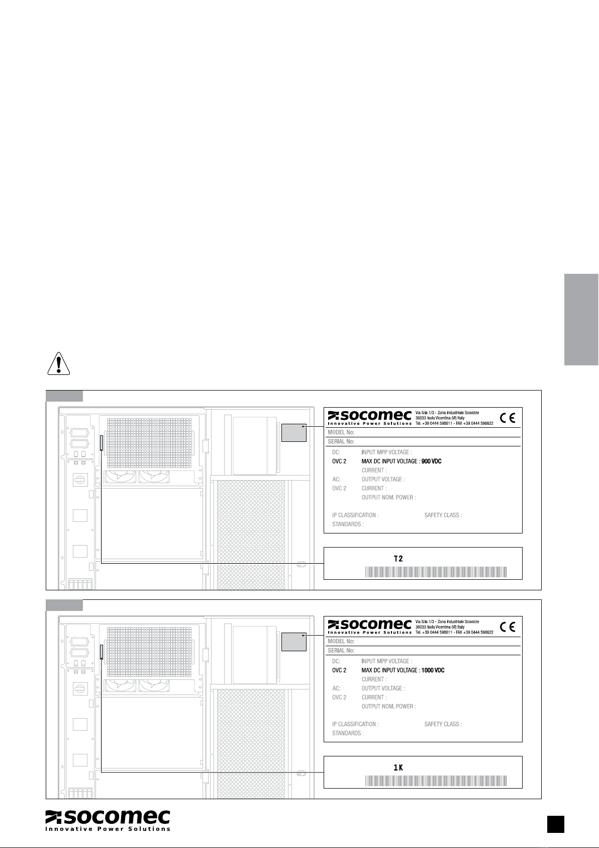
1.4. IDENTIFICATION DATA PLATE . . . . . . . . . . . . . . . . . . . . . . . . . . . . . . . . . . . . . 5
2. DESCRIPTION OF THE SYSTEM . . . . . . . . . . . . . . . . . . . . . . . . . . . . . . . . . . . . . . . . . . . . . . 6
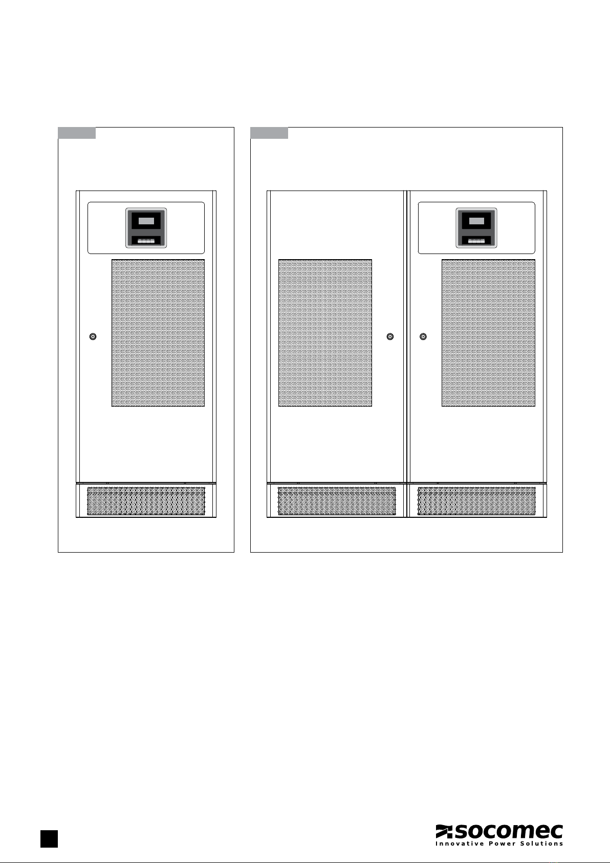
2.1. OVERVIEW . . . . . . . . . . . . . . . . . . . . . . . . . . . . . . . . . . . . . . . . . . . . . . . . . . . . 6
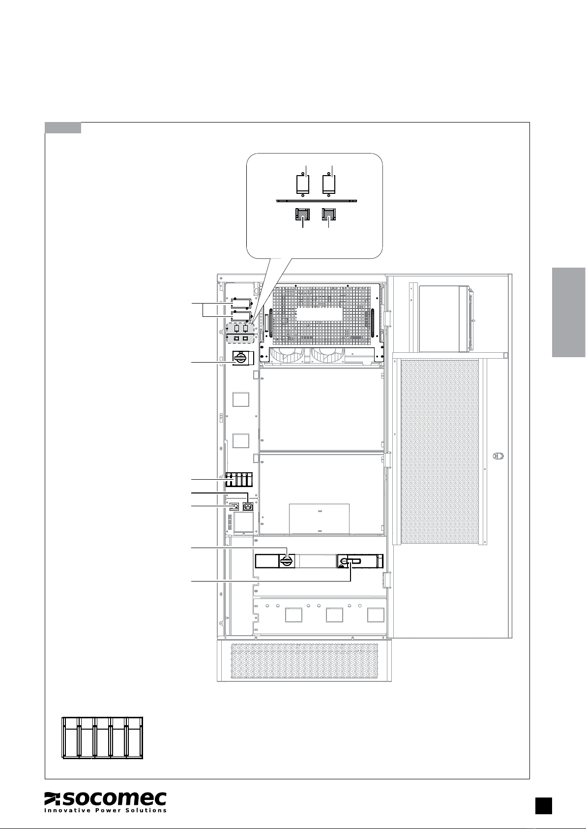
2.2. DESCRIPTION . . . . . . . . . . . . . . . . . . . . . . . . . . . . . . . . . . . . . . . . . . . . . . . . . 7
2.3. TECHNICAL DATA . . . . . . . . . . . . . . . . . . . . . . . . . . . . . . . . . . . . . . . . . . . . . 16
3. PREREQUISITES . . . . . . . . . . . . . . . . . . . . . . . . . . . . . . . . . . . . . . . . . . . . . . . . . . . . . . . . . 17
3.1. INSTALLATION SITE CONDITIONS . . . . . . . . . . . . . . . . . . . . . . . . . . . . . . . . . 17
4. TRANSPORT AND UNWRAPPING. . . . . . . . . . . . . . . . . . . . . . . . . . . . . . . . . . . . . . . . . . . . 18
5. INSTALLATION . . . . . . . . . . . . . . . . . . . . . . . . . . . . . . . . . . . . . . . . . . . . . . . . . . . . . . . . . . . 19
5.1. ELECTRICAL INSTALLATION REQUIREMENTS . . . . . . . . . . . . . . . . . . . . . . . 19
5.2. CONNECTING THE PHOTOVOLTAIC GENERATOR AND MAIN AC NETWORK
TO THE POWER TERMINALS OF THE SUNSYS P33TR INVERTER. . . . . . . . 21
5.3. CONNECTING THE PHOTOVOLTAIC GENERATOR AND MAIN AC NETWORK
TO THE POWER TERMINALS OF THE SUNSYS P66TR INVERTER. . . . . . . . 22
5.4. CONNECTING THE PHOTOVOLTAIC GENERATOR AND MAIN AC NETWORK
TO THE POWER TERMINALS OF THE SUNSYS P66TL INVERTER . . . . . . . . 24
5.5. CONNECTING THE PHOTOVOLTAIC GENERATOR AND MAIN AC NETWORK
TO THE POWER TERMINALS OF THE SUNSYS P100TL INVERTER . . . . . . . 26
5.6. AUXILIARY POWER SUPPLY . . . . . . . . . . . . . . . . . . . . . . . . . . . . . . . . . . . . . 28
5.7. OPTIONAL INPUT FOR EXTERNAL INTERFACE PROTECTION . . . . . . . . . . . 28
6. OPERATING MODES . . . . . . . . . . . . . . . . . . . . . . . . . . . . . . . . . . . . . . . . . . . . . . . . . . . . . . 29
6.1. ACTIVATING THE INVERTER FOR THE FIRST TIME . . . . . . . . . . . . . . . . . . . . 29
6.2. SWITCHING ON THE INVERTER . . . . . . . . . . . . . . . . . . . . . . . . . . . . . . . . . . 32
6.3. SWITCHING OFF THE INVERTER. . . . . . . . . . . . . . . . . . . . . . . . . . . . . . . . . . 32
7.1. MEANING OF THE LUMINOUS STATUS BAR. . . . . . . . . . . . . . . . . . . . . . . . . 37
7. MIMIC PANEL . . . . . . . . . . . . . . . . . . . . . . . . . . . . . . . . . . . . . . . . . . . . . . . . . . . . . . . . . . . 37
7.2. DISPLAY MENU . . . . . . . . . . . . . . . . . . . . . . . . . . . . . . . . . . . . . . . . . . . . . . . 38
7.3. MENU TREE . . . . . . . . . . . . . . . . . . . . . . . . . . . . . . . . . . . . . . . . . . . . . . . . . . 39
7.4. KEYPAD LOCKING . . . . . . . . . . . . . . . . . . . . . . . . . . . . . . . . . . . . . . . . . . . . . 40
7.5. MIMIC PANEL OVERVIEW . . . . . . . . . . . . . . . . . . . . . . . . . . . . . . . . . . . . . . . 40
7.6. SERVICE MENU . . . . . . . . . . . . . . . . . . . . . . . . . . . . . . . . . . . . . . . . . . . . . . . 42
8. COMMUNICATION . . . . . . . . . . . . . . . . . . . . . . . . . . . . . . . . . . . . . . . . . . . . . . . . . . . . . . . 43
8.1. MULTILEVEL COMMUNICATION . . . . . . . . . . . . . . . . . . . . . . . . . . . . . . . . . . 43
8.2. MODBUS/TCP INTERFACE . . . . . . . . . . . . . . . . . . . . . . . . . . . . . . . . . . . . . . 43
9. PREVENTIVE MAINTENANCE . . . . . . . . . . . . . . . . . . . . . . . . . . . . . . . . . . . . . . . . . . . . . . . 44
9.1. REGULAR INSPECTION OF THE INVERTER . . . . . . . . . . . . . . . . . . . . . . . . . 45
9.2. PREVENTIVE INVERTER MAINTENANCE . . . . . . . . . . . . . . . . . . . . . . . . . . . . 45
10. TROUBLESHOOTING . . . . . . . . . . . . . . . . . . . . . . . . . . . . . . . . . . . . . . . . . . . . . . . . . . . . 46
10.1. SYSTEM WARNINGS . . . . . . . . . . . . . . . . . . . . . . . . . . . . . . . . . . . . . . . . . . . 46
10.2. INVERTER WARNINGS. . . . . . . . . . . . . . . . . . . . . . . . . . . . . . . . . . . . . . . . . . 46
10.3. SYSTEM ALERTS . . . . . . . . . . . . . . . . . . . . . . . . . . . . . . . . . . . . . . . . . . . . . . 47
10.4. INVERTER ALERTS . . . . . . . . . . . . . . . . . . . . . . . . . . . . . . . . . . . . . . . . . . . . 47

4SUNSYS P33TR - P66TL/TR - P100TL/TR - Ref.: IOMSUNMOXX00-GB 03
1.1. PERSONAL SAFETY PRECAUTIONS
To prevent personal injury and damage to property please read the following warnings before activating the device for the first time:
Read the operating instructions beforehand!
- Observe the safety warnings!
- Observe the user information!
Risk of electric shocks from live device parts!
In the event of system maintenance, carry out the following steps beforehand:
• Disconnect the photovoltaic system and the AC power supplies.
• Make sure the system cannot be restarted.
• Make sure the electricity supply has been disconnected.
• Earth the equipment sub-assemblies and short-circuit them.
• Cover or separate nearby live device units.
• Before working on circuits upstream make sure the inverter is disconnected by opening the DC disconnection switches.
• If there are field panels upstream of the inverter attach label to them displaying the following information:
WARNING!
DEVICE WITH SEVERAL HAZARDOUS VOLTAGE POWER SUPPLY SOURCES INSIDE EVEN AFTER DISCONNECTION DEVICES
HAVE BEEN OPENED.
ADOPT ALL SAFETY MEASURES REQUIRED FOR PROCEDURES ON LIVE PARTS.
The following measures are required:
- To prevent personal injury and damage to property, the device should only be used by qualified personnel with electrical and
technical training.
- The qualified technician must have read the operating instructions.
- National accident prevention standards must be observed.
- Maintenance and repair procedures must only be carried out by trained personnel authorised by Socomec. The user is strictly
prohibited from carrying out procedures which could involve compromise the integrity of the inverter (for example, removing inverter
modules).
During installation, observe the following:
- Observe the connection conditions and technical data.
- Observe standards regarding electrical installation, e.g. cable cross-section, contactor connection and earthing.
- Do not touch any components and electronic contacts (electrostatic charge could destroy the components).
DANGER!
Risk of electric shock from live device parts!
SUNSYS P inverters can be connected to a maximum of three separately protected power supplies:
1 DC cable - Photovoltaic generator power supply (separate for the three modules or shared)
2 AC cable - Power from the mains network, supplied by the electricity company
3 AC cable - Auxiliary power supply
• Before carrying out any work make sure the electricity supply has been disconnected.
• All DC power supplies should be considered as part of the same circuit, even in the configuration with centralised
multi-string inverter. Before carrying out any work make sure all electricity supplies have been disconnected.
DANGER!
Risk of electric shock from live device parts!
The intermediate inverter circuit may be live even after it has been deactivated.
• Wait 5 minutes for the power to disperse and make sure that there is none remaining.
DANGER!
Risk of electric shock from live device parts!
The photovoltaic modules are live as soon as they are exposed to sunlight.
• Take suitable measures and make sure there is no power remaining.
1. SAFETY INSTRUCTIONS
5 min

5
SUNSYS P33TR - P66TL/TR - P100TL/TR - Ref.: IOMSUNMOXX00-GB 03
ENGLISH
1. SAFETY INSTRUCTIONS
1.2. COMPLIANT USE
SUNSYS P are photovoltaic inverters for the conversion of direct current into alternating current in compliance with the mains network.
Any use other than the specified purpose will therefore be considered as improper. The manufacturer/supplier shall not be held
responsible for damage resulting from this. The risk and responsibility lies with the system manager.
SUNSYS P are constructed in accordance with current technical regulations and official safety standards. Before shipment all devices
undergo technical safety testing. Nevertheless, incorrect or improper use may endanger the life or health of the operator and third
parties, or damage equipment or other materials.
Compliant use also includes observing operating instructions. SUNSYS P must be installed by specialist personnel deemed respon-
sible for complying with existing standards. Repair work may only be carried out by authorised centres. Arbitrary and unauthorised
work may have fatal consequences, cause injury or damage property. In the event of damage, SOCOMEC shall assume no respon-
sibility and the warranty shall be void.
1.3. STANDARDS AND GUIDELINES
When carrying out electrical installation, all standards specified by the IEC and the electricity supplier must be observed.
All national standards apply to photovoltaic systems must be respected during insatallation and configuration.
1.4. IDENTIFICATION DATA PLATE
WARNING!
Before connecting the modules, check that they are fully compatible with the model of system in use.
XXXXXXXXXX XXX XXXXX-XX-MOD33+T2
XXXXXXXXXX XXX XXXXX-XX-MOD33+1K
1.4-1 900 V identification plates
1.4-2 1000 V identification plates

6SUNSYS P33TR - P66TL/TR - P100TL/TR - Ref.: IOMSUNMOXX00-GB 03
2. DESCRIPTION OF THE SYSTEM
2.1. OVERVIEW
2.1-1 SUNSYS P33 TR
SUNSYS P66 TR
SUNSYS P66 TL
SUNSYS P100 TL
2.1-2 SUNSYS P100TR
Transformer Inverter

7
SUNSYS P33TR - P66TL/TR - P100TL/TR - Ref.: IOMSUNMOXX00-GB 03
ENGLISH
2. DESCRIPTION OF THE SYSTEM
2.2. DESCRIPTION
12345
2.2-1 SUNSYS P33TR with the door open and the 33 kW power module
Communication slots
Module A
Module A output
disconnection switch
Button
TEST
(option)
RS232RS232
Button
RESET
(option)
IEC320 AUX output for assistance
IEC320 AUX power input
Detail
Disconnection
switches with fuse
Inverter output disconnection switch
Module A input disconnection switch
1 Disconnection switch for isolation controller (option)
2 Disconnection switch for isolation controller (option)
3 Disconnection switch for IEC320 connector AUX power supply
4 Disconnection switch for IEC320 connector for assistance
5 Fan fuse
Disconnection switches with fuse
(see detail below)

8SUNSYS P33TR - P66TL/TR - P100TL/TR - Ref.: IOMSUNMOXX00-GB 03
8
2.DESCRIPTION OF THE SYSTEM
12345
2.2-2 SUNSYS P66TR with the door open and the two 33 kW power modules
Communication slots
Module A
Module B
Module A output
disconnection switch
RS232RS232
Module B output
disconnection switch
IEC320 AUX output for assistance
IEC320 AUX power input
Detail
Disconnection
switches with fuse
Inverter output disconnection switch
Module B input disconnection switch
Module A input disconnection switch
1 Disconnection switch for isolation controller (option)
2 Disconnection switch for isolation controller (option)
3 Disconnection switch for IEC320 connector AUX power supply
4 Disconnection switch for IEC320 connector for assistance
5 Fan fuses
Disconnection switches with fuse
(see detail below)
Button
TEST
(option)
Button
RESET
(option)

9
SUNSYS P33TR - P66TL/TR - P100TL/TR - Ref.: IOMSUNMOXX00-GB 03
ENGLISH
12345
2.2-3 SUNSYS P66TL with the door open and the two 33 kW power modules
Communication slots
Module A
Module B
Module A output
disconnection switch
RS232RS232
Module B output
disconnection switch
IEC320 AUX output for assistance
IEC320 AUX power input
Detail
Disconnection
switches with fuse
Module B input disconnection switch
Module A input disconnection switch
1 Disconnection switch for isolation controller (option)
2 Disconnection switch for isolation controller (option)
3 Disconnection switch for IEC320 connector AUX power supply
4 Disconnection switch for IEC320 connector for assistance
5 Fan fuses
Disconnection switches with fuse
(see detail below)
Button
TEST
(option)
Button
RESET
(option)
2. DESCRIPTION OF THE SYSTEM

10 SUNSYS P33TR - P66TL/TR - P100TL/TR - Ref.: IOMSUNMOXX00-GB 03
10
12345
2.2-4 SUNSYS P100TL with the door open and the three 33 kW power modules
Communication slots
Module A output disconnection switch
Module B output disconnection switch
Module A input disconnection switch
Module B input disconnection switch
Module C input disconnection switch
Module C output disconnection switch
Inverter output disconnection switch
Module A
Module B
Module C
RS232RS232
IEC320 AUX output for assistance
IEC320 AUX power input
Detail
Disconnection
switches
with fuse
1 Disconnection switch for isolation controller (option)
2 Disconnection switch for isolation controller (option)
3 Disconnection switch for IEC320 connector AUX power supply
4 Disconnection switch for IEC320 connector for assistance
5 Fan fuse
Disconnection switches with fuse (see detail below)
Button
TEST
(option)
Button
RESET
(option)
2.DESCRIPTION OF THE SYSTEM

11
SUNSYS P33TR - P66TL/TR - P100TL/TR - Ref.: IOMSUNMOXX00-GB 03
ENGLISH
The SUNSYS P series covers a range of power from 33.3 to 100 kW and consists of 1, 2 or 3 modules of 33.3 kW each.
Each module converts the energy provided by the solar panels, using a Maximum Power Point Tracking (MPPT) algorithm to fully
exploit the features of the photovoltaic cells.
The DC terminals of all modules can be connected to the same photovoltaic field (centralised modular inverter with single MPPT),
or can have different photovoltaic fields (centralised multi-string inverter with separate MPPTs).
IMD
3Ph+PE
DC +/–
GND
IMD
Q1A
Q3A
T1
K1
Q70
X90
X10A
X10A
X90
DC +/–DC +/–
X10A
X90 X10B X10A
X10B
Q1B
Q3B
X90
Q70
Q3A
T1
K1
Q1A
IMD
3Ph+PE
GND
IMD
2.2-5 Simplified wiring diagram of the SUNSYS P33TR system
2.2-6 Simplified wiring diagram of the SUNSYS P66TR system
Photovoltaic field
Photovoltaic field Photovoltaic field
AC main network
Option
SPD-IN
Option
SPD-IN
Option
SPD-IN
Option
IMD
Option
IMD
Option
SPD-OUT
Option
SPD-OUT
Option
earthing kit + IMD
Option
earthing kit + IMD
Option
Common DC
AC main network
2. DESCRIPTION OF THE SYSTEM

12 SUNSYS P33TR - P66TL/TR - P100TL/TR - Ref.: IOMSUNMOXX00-GB 03
12
DC +/–DC +/–
X10A
X90 X10B X10A
X10B
Q1B
Q3B
X90
Q3A
Q1A
IMD
3Ph+PE
GND
IMD
2.2-7 Simplified wiring diagram of the SUNSYS P66TL system
Photovoltaic field Photovoltaic field
Option
SPD-IN
Option
SPD-IN
Option
IMD
Option
earthing kit + IMD
Option
Common DC
AC main network
2.DESCRIPTION OF THE SYSTEM

13
SUNSYS P33TR - P66TL/TR - P100TL/TR - Ref.: IOMSUNMOXX00-GB 03
ENGLISH
IMD
3Ph+PE
3Ph
X10
T1
Q70
X90
3Ph+PE
K1
X90
Q3A Q3B
DC +/– DC +/– DC +/–
Q1B Q1CQ1A
X10B X10C
X10A
X10AX10BX10C
X90
Q3C
X90 X10
GND
IMD
Inverter
SUNSYS P100TL
Transformer
SUNSYS P100TR
Field
photovoltaic Field
photovoltaic Field
photovoltaic
AC main network
AC main network
Power supply network
Option
SPD-IN
Option
SPD-IN
Option
SPD-IN
Option
SPD-OUT
Option
Common DC
Option
IMD
2.2-8 Simplified wiring diagram of the SUNSYS P100TL system (with Sunsys P100TR)
Option
earthing kit + IMD
2. DESCRIPTION OF THE SYSTEM

14 SUNSYS P33TR - P66TL/TR - P100TL/TR - Ref.: IOMSUNMOXX00-GB 03
14
2.2-9 System principle diagram
DC
AC
DC
AC
DC
AC
DC
AC
DC
AC
DC
AC
2.2-10 Centralised modular inverter 2.2-11 Centralised multi-string inverter
2.DESCRIPTION OF THE SYSTEM

15
SUNSYS P33TR - P66TL/TR - P100TL/TR - Ref.: IOMSUNMOXX00-GB 03
ENGLISH
B
A
C
B
A
C
2.2-12 Load sharing 2.2-13 Load sharing + Energy saver
In the case of the centralised modular inverter, the 33.3 kW modules run on Energy Saver mode.
This type of operation has two advantages:
• Longer equipment lifetime, as the individual modules are switched on and off at random and run for less time on average, instead
of all being switched on and off at the same time.
• Increased efficiency, as only the equipment actually required is activated and operates under optimal efficiency conditions (30-60%
of rated power).
In the case of centralised multi-string inverters, the MPPT algorithm of each module runs independently to maximise the power
supplied by the photovoltaic panels.
The inverter is equipped with an isolation transformer as standard, and can therefore be used with all photovoltaic panel technology
(crystalline, thin film, back contact etc.). For technology which requires one of the photovoltaic generator poles to be earthed, the
special optional kit (GND) must be used.
2.2.1. Options
SUNSYS P can be ordered together with the following options:
• Earthing: PV generator + or – pole earthed (GND)
• Permanent isolation controller (IMD)
• AC over-voltage dischargers (SPDO)
• DC over-voltage dischargers (SPDI)
• Cable fastening brackets
For detailed information regarding the options refer to the relevant documentation.
Eciency
Load rate
% load
% load
% load
% load
% load
% load
Load rate
Eciency
2. DESCRIPTION OF THE SYSTEM

16 SUNSYS P33TR - P66TL/TR - P100TL/TR - Ref.: IOMSUNMOXX00-GB 03
16
SUNSYS
P33TR
SUNSYS
P66TL
SUNSYS
P66TL 1K
SUNSYS
P66TR
SUNSYS
P100TL
SUNSYS
P100TL 1K
SUNSYS
P100TR
DC input
DC rated current
80 A 160 A 240 A
Max. DC voltage
900 V 900 V 1000 V 900 V 900 V 1000 V 900 V
Stop voltage
350 V 350 V 400 V 350 V 350 V 400 V 350 V
MPP field *
450 to 800 V 450 to 800 V 485 to 850 V 450 to 800 V 450 to 800 V 485 to 850 V 450 to 800 V
MPPT no.
1 1-2 1-3
AC output
Rated power
33.3 kW/kVA 66.7 kW/kVA 100 kW/kVA
Maximum power (30 min.)
36.6 kW/kVA 73.4 kW/kVA 110 kW/kVA
AC voltage
Output voltage
400 V 3ph 280 V 3ph 320 V 3ph 400 V 3ph 280 V 3ph 320 V 3ph 400 V 3ph
Protection
63 A curve D 200 A curve C 160 A curve C 125 A curve D 250 A curve C 250 A curve C 200 A curve D
Power factor **
≥0.99
Distortion factor
<3%
Efficiency
η% (rat.)
96.1 97.6 98.0 96.3 97.6 98.0 96.4
η%(euro)
95.2 97.3 97.8 95.6 97.3 97.8 95.8
Auxiliary power supp.
In operation
<30 W
On Standby
<10 W
Environmental conditions
Cooling air requirements
480 m3/h 960 m3/h 1280 m3/h 1440 m3/h 1760 m3/h
Dissipated power
1750 W 2400 W 3500 W 3650 W 5250 W
Dissipated power
5980 BTU/h 8184 BTU/h 11950 BTU/h 12450 BTU/h 17900 BTU/h
Temperature range
During operation
-5°C to 40°C (from 40°C to 55°C with downgrading)
During transportation
-5°C to 55°C
Relative humidity
5% to 95% without condensation
Environmental category in accor-
dance with EN 62109-1
Non-air-conditioned indoor space
Altitude
≤1000 m without derating
Protection class in accordance
with EN 60529
IP20
Pollution class in accordance with
EN60664-1
3
Pulse resistance voltage
in accordance with EN 60060-1
AC terminals
2.5 kV
Pulse resistance voltage
in accordance with EN 60060-1
DC terminals
4 kV
Mechanical characteristics
Dimensions (LxHxD)
600x1400x795
mm 600x1400x795 mm 600x1400x795
mm 600x1400x795 mm 1200x1400x
795 mm
Weight
330 kg 125 kg 525 kg 190 kg 190 + 580 kg
Noise (front, 1 m) 60 dB 64 dB
Communication ports
Serial RS232/485 JBUS
2.3. TECHNICAL DATA
2.DESCRIPTION OF THE SYSTEM
* The full power MPPT voltage range is valid at nominal mains condition
** Adjustable according main supplier condition

17
SUNSYS P33TR - P66TL/TR - P100TL/TR - Ref.: IOMSUNMOXX00-GB 03
ENGLISH
3. PREREQUISITES
3.1. INSTALLATION SITE CONDITIONS
The installation site must meet the following requirements:
- The inverter is designed for use within non-air-conditioned rooms in accordance with standard IEC 62109-1. Th inverter is not
designed for outdoor use.
- The foundations must be able to withstand the relevant weight (inverter, transportation device) and suited to the base. Stability
must also be guaranteed.
- The ambient temperatures, relative humidity and altitude of the installation site are indicated in the technical data table.
- Avoid environments which are dusty or which contain dust from conductive or corrosive materials (e.g. dust from metal or chemical
solutions).
- The inverter has front access for handling devices; nevertheless, a space of at least 1.5 metres should be left free at the front of
the inverter for any maintenance work required.
- The rear of the inverter must be at least 40 cm away from the wall or other obstacles to guarantee sufficient ventilation (see figure).
3.1-1
free area
SUNSYS SUNSYS SUNSYS
40 cm1.5 m

18 SUNSYS P33TR - P66TL/TR - P100TL/TR - Ref.: IOMSUNMOXX00-GB 03
WARNING!
After completing all the procedures, fit the protective skirting
4. TRANSPORT AND UNWRAPPING
40 cm
4.1-1 4.1-2
4.1-4
Position the inverter in the installation zone. The SUNSYS P100TL inverter must be fixed to the floor
4.1-3
Remove the protection
SUNSYS P100TL inverter
SUNSYS P100TR
transformer cabinet
Rear side

19
SUNSYS P33TR - P66TL/TR - P100TL/TR - Ref.: IOMSUNMOXX00-GB 03
ENGLISH
5. INSTALLATION
DANGER!
Risk of electric shock from live device parts!
In the event of system maintenance, carry out the following steps beforehand:
• Disconnect the photovoltaic system.
• Make sure the photovoltaic system cannot be restarted.
• Make sure the mains electricity supply has been disconnected.
• Earth the device units and short-circuit them.
• Cover or separate the nearby live device units.
•
Before working on the circuits upstream make sure the inverter is disconnected by opening the DC disconnection switches
.
DANGER!
Risk of electric shock from live device parts!
SUNSYS P can be connected to a maximum of three power supplies:
1 DC cable - Photovoltaic generator power supply (separated for the three modules or shared)
2 AC cable - Power from the mains network, supplied by the electricity company
3 AC cable - Auxiliary power supply
• Before carrying out any work, make sure the electricity supply has been disconnected.
• All DC power supplies should be considered as part of the same circuit, even in the configuration with centralised multi-string
inverter. Before carrying out any work, make sure all electricity supplies have been disconnected.
DANGER!
Risk of electric shock from live device parts!
The intermediate inverter circuit may be live even after it has been deactivated.
• Wait 5 minutes for the power to disperse and make sure that there is none remaining.
DANGER!
Risk of electric shock from live device parts!
The photovoltaic modules are live as soon as they are exposed to sunlight.
• Take suitable measures and make sure there is no power remaining.
SUNSYS P are designed for instant application. Only the AC and DC cables coming from outside must be installed and the inverter
configured.
5.1. ELECTRICAL INSTALLATION REQUIREMENTS
The installation and system must comply with existing national legislation.
The fixed power distribution unit must include protection and disconnection for the main AC network for the auxiliary network.
The following table indicates the sizing of AC protection devices that will ensure correct installation.
Model Network cable cross-section
Main AC (mm2) 1
Magneto-thermal switch protecting
the main AC network
Differential AC protection
(optional)
SUNSYS P33TR min. 16 / max. 120 63 A type D 20.3 A type AC or A
SUNSYS P66TR min. 35 / max. 120 125 A type D 20.3 A type AC or A
SUNSYS P66TL min. 70 / max. 120 200 A type C 0.3 A type AC or A
SUNSYS P66TL 1K min. 70 / max. 120 160 A type C 0.3 A type AC or A
SUNSYS P100TL 120 250 A type C 0.3 A type AC or A
SUNSYS P100TL 1K 120 250 A type C 0.3 A type AC or A
SUNSYS P100TR min. 70 / max. 120 200 A type D 20.3 A type AC or A
1. Determined by the size of the terminals
2. Recommended magneto-thermal switch: three poles with intervention threshold ≥ 10 In
The auxiliary power supply socket must be protected with a 16 A magneto-thermal switch, curve C, and from category 2 over-
voltages or greater.
5 min

20 SUNSYS P33TR - P66TL/TR - P100TL/TR - Ref.: IOMSUNMOXX00-GB 03
20
5. INSTALLATION
The following table indicates the sizing of the wires originating from the photovoltaic generator for correct installation.
Inverter size PV generator cable cross-section in case of
shared DC inputs (mm2) 1
PV generator cable cross-section in case of
separate DC inputs (mm2) 2
33 kW min. 25 / max. 120 (M8) N.A.
66 kW min. 50 / max. 120 (M8) min. 25 / max. 120 (M8)
100 kW min. 95 / max. 120 (M8) min. 25 / max. 120 (M8)
1. Determined by the size of the terminals
2. Up to 2 cables can also be connected at the same point, max. 2x50 mm2
WARNING!
The inverter is designed for transient over-voltages in category II installations for AC terminals. If the inverter may be
subjected to transient over-voltages in category III installations, protective SPDs must be provided for the AC power
supply network. The SPDO option, designed to protect against category III over-voltages, can be fitted directly to
the inverter. If it is used, the distance between the inverter and type I centralised SPD protection must be ≥15 m.
WARNING!
The inverter is designed for transient over-voltages in category II installations for DC terminals. If the inverter may
be subject to transient over-voltages in category III installations, or if the distance from the SPDs in the photovoltaic
field is excessive, protective SPDs must be fitted near the inverter. The SPDI option, designed to protect against
over-voltages in photovoltaic applications, can be fitted directly to the inverter.
NOTE
DC inputs do not require protection against over-voltages, if fewer than three inverter modules are connected to
the same photovoltaic generator.
NOTE
Functional panel earthing (optional): for correct operation, some types of photovoltaic panel require one of the two
poles to be earthed. The special optional kit (GND) can be used to earth the positive or negative pole of the photo-
voltaic generator. For further details and instructions, please refer to the kit (GND) installation and operating manual.
IT SYSTEM
With the photovoltaic panels isolated from earth, the circuit consisting of the panels and the inverter is configured
like an IT system. We therefore recommend a permanent isolation controller is used in the system or built into the
inverter (IMD option).
This manual suits for next models
5
Table of contents
Other socomec Inverter manuals
Popular Inverter manuals by other brands

GYS
GYS PSW 600 W Translation of the original instructions

ECTIVE
ECTIVE CSI Series Installation and operating instructions

Shinefar
Shinefar SF-1k-TL user manual

SMA
SMA Sunny Island 5048 Technical description

Pulsar
Pulsar PG4500BiSRCO Operator's manual

MULTIQUIP
MULTIQUIP TLG8SSK4F Operation and parts manual