SpectRah FUSION SL70 Owner's manual

FUSION
SL 70
bar
Installation and operation Instructions
Copyright Spectrah 2019
Made In Australia from local and imported components
Copyright Spectrah 2018
Made In Australia from local and imported components
www.spectrah.com.au
Designed and built in Australia to relevant AS/NZ general requirements and tests
Thank you for purchasing the Spectrah SL70 LED Supplementary
Horticulture Lighting System. To achieve the best performance from
your SL70, please follow the recommendations and guidelines published
in this document.
To ensure long life and reliability from your SL70 Bars please adhere to the following guidlines
The SL70 components are designed to IP67 and are suitable for use in installations where
sprinklersareused,howeverDONOTSUBMERGECOMPONENTS.
DriverunitsaredesignedtoIP65howeverthestandardmainsACplugisnot.Donotexpose
the mains plug to wet or damp conditions. If the driver needs to operate in a damp or wet
locationitmustbeinstalledwithanIP65junctionboxbyasuitablyqualifiedelectrician.
AvoidtouchingtheLEDlensmembrane.IfcleaningisrequireduseIPAorwarmsoapywater
withalintfreeclothtogentlywipethemembrane.Donotusevolatilesolventsofanykind.
The SL70 bars are designed to be used in tandem. Single bar operation is not
recommended however, If operation of a single bar is absolutely necessary then it must be
runwiththeoutputdimmersetatapproximately50%.
Neveroperatetheunitsfacedownorlayingdirectlyonanysurface.Themounts,attachedto
a suitable supporting structure, must be used at all times the bars are employed in any
installationpermutationotherthandirectsuspension.
Alwaysmaintainaminimumclearanceof50mmbetweentheLEDlightemittingsurfaceand
anyothersurface.
Before unplugging any part of the system disconnect driver from mains supply. It is
recommended to disconnect each module prior to repositioning to avoid damaging cable
entries.
Warranty
The LED and Driver modules are provided with a warranty of five years against manufacturing defects or failure to perform to specifications provided
that, installation has been carried out in accordance with these instructions and said components have not been subjected to incorrect operation or
maintenance, unauthorised disassembly or modification or any other damage arising from an intervening cause. Refer to full warranty document
on websiteformoredetail.
www.spectrah.com.au/fusion/warranty
Input 180 - 240 Vac 0.12 - 0.2 A 47 - 63 Hz
Output 36.0 Vdc 900mA 32.5 W
Maximum Suspended Weight 1.00kg
0 0
Normal Operating Temperature -30 C to +40 C Ambient
Basic Specifications
Photometric Specifications
The SL70 Bars are available in 3 different photometric spectrums.
For specific PPFD and wavelength details please log on to our
website.
A coloured dot at the centre of the Spectrah Eye Logo on each bar
identifies its output:
No Dot - 12.5% Blue
Red Dot - 2.5% Blue
Yellow Dot - 25% Blue
Copyright Spectrah 2018
Made In Australia from local and imported components
www.spectrah.com.au
Copyright Spectrah 2019
Made In Australia from local and imported components
www.spectrah.com.au
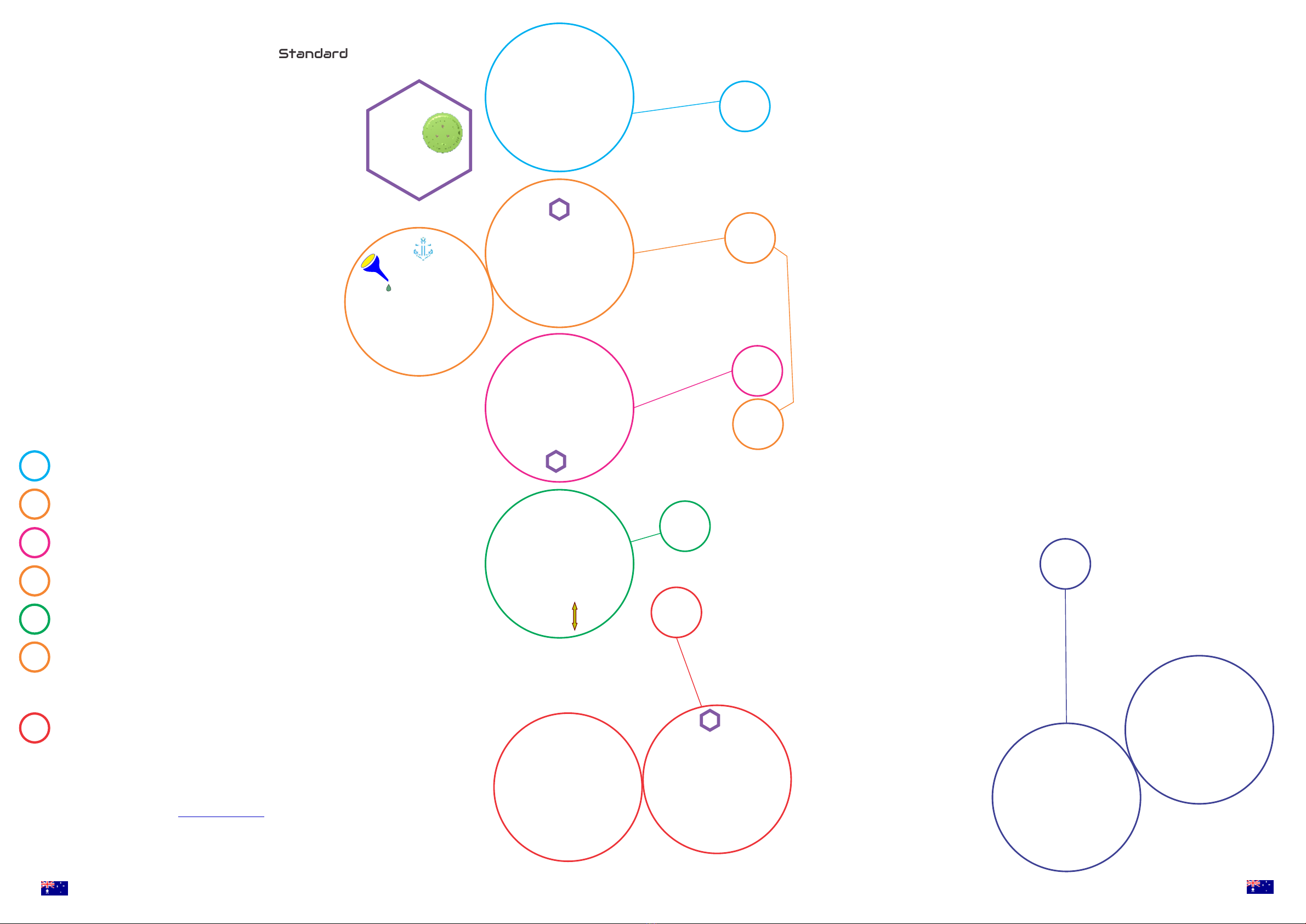
Standard Kit Contents Typical Mounting
Scenarios
Correctly align
plug pins before
insertion
TheSL70Bar hasbeen designed as aside,intra-canopy,
and upward supplemental lighting source in dense top lit
environments. Provided the general Do’s and Dont’s are
adhered to, its flexibility affords multiple installation
permutations.Somesimpleexamplesareillustrated.
Getting Started
Install an SL70 Module by correctly aligning the plug pins, inserting the plug, and tightening the
grey retaining cap until resistance is felt against the ‘O’ ring seal. Avoid over tightening the cap.
Choose a layout appropriate to your requirements and assemble the SL 70 making
reference to the appropriate detailed illustration balloons. The basic suspension
installation is described to illustrate the interconnection procedure.
Using a cable tie or similar, attach the Stainless Steel snap hook to a suitable supporting member and
install the Hanger and Cable Guide assemblies. Route the assembly as dictated by enclosure constraints
Unscrew the dust cap on the lower end of the module, identify the appropriate end of the Module
Interconnect cable, correctly align plug pins, insert and tighten Grey retaining cap as before.
Install the second SL70 Module using same procedure as the first.
a
b
a
a
Adjust suspension height by loosening cable clamping knob, feed or pull the cable through the device
until desired suspension height is achieved. Re-clamp the cable and avoid over tightening the knob.
Allow the assembly to hang freely. When the lay of the suspension wire has settled and the modules stop
rotating, beam direction can be adjusted by gripping plug firmly and rotating module body to the desired beam
o
angle. 170 rotation either side of the internal mechanical stop is available. Adjust upper module first and repeat
for lower module. The assembly will now hang freely at the set angle. NOTE; rotation may be stiff if the internal
seal has become dry with time. A few drops of WD40 or Silicone spray where indicated will rectify the problem.
b
SL 70 LED Modules
Cable Guide Assembly
Stainless Steel Snap Hook
Hanger Assembly
LED Driver Module
Teflon Support Cable(4 Metres)
Module Interconnect
Velcro Straps
Swivel Mounts
Cable Travel Clamp
Connect the driver by correctly aligning the plug pins, inserting the plug, and tightening the
grey retaining cap until resistance is felt against the ‘O’ ring seal. Avoid over tightening the
cap. Plug the driver into a suitable AC mains socket and turn on. Illumination intensity can
be controlled by the PPFD dimmer knob. Rotate clockwise to increase illumination and
anti-clockwise to decrease. Illumination may be dimmed to ‘OFF’
Drivers equipped with the CASAMBI BlueTooth option can be controlled by firstly downloading
the Smartphone App from Once installed, and with your driver plugged in,
your Smartphone will recognise the device. You can now follow the prompts to pair your device
and take advantage of all the smart functions the Casambi software has to offer.
NOTE; Casambi equipped drivers do not have a manual dimming knob
www.casambi.com
o
340
Table of contents
Other SpectRah Lighting Equipment manuals


