SpectraLink Corporation Installation, Configuration, and Administration
NetLink Telephony Gateway
Part Number: 72-0065-02-R.doc Page 10
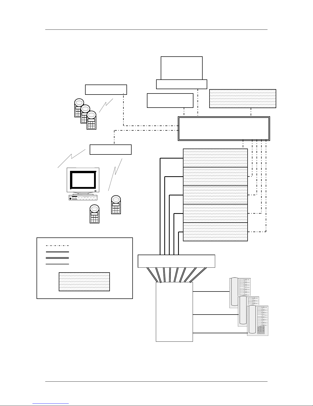
2.6 System Components
NetLink Wireless Telephones
Employees can carry handsets to place and receive calls as they move throughout the
building. The handsets are to be used on-premises; they are not cellular or satellite
phones. They are connected to the facility's existing telephone system and to the
NetLink Telephony Gateway. Just like wired telephones, they can receive calls
directly, receive transferred calls, transfer calls to other extensions, and make outside
and long distance calls (subject to the restrictions applied in your facility.)
NetLink Telephony Gateway
The NetLink Telephony Gateway serves as the connecting point, or gateway,
between the LAN and the existing telephone system. One or more NetLink
Telephony Gateways are typically installed in the telephone equipment room. The
eight port model supports up to eight telephone lines and handsets and the 16 port
model supports up to 16 telephone lines and handsets. Up to 40 NetLink Telephony
Gateways can be connected to the LAN to support additional telephone lines. If five
or more NetLink Telephony Gateways are connected to the LAN, a NetLink SVP
Server must be installed to handle the increased call volume.
SpectraLink offers digital NetLink Telephony Gateways that work with the digital
ports on most common brands of telephone systems (PBX or key systems). We also
offer an analog NetLink Telephony Gateway that works with telephone systems
(CO, PBX, or Key Systems) with analog (loop start) ports.
Access points
Access points (APs) are supplied by third party vendors, APs provide the connection
between the wired Ethernet LAN and the wireless (802.11) LAN. APs must be
positioned in all areas where NetLink Wireless Telephones will be used. The number
and placement of APs will affect the coverage area and capacity of the wireless
system. Typically, the requirements for use of NetLink Wireless Telephones are
similar to that of wireless data devices. Contact SpectraLink, or a certified
SpectraLink distributor, for specific information about your facility’s needs.
The NetLink system must connect to APs that utilize SVP. Refer to the NetLink
Wireless Telephone WLAN Compatibility List for a list of APs that support SVP.
Ethernet switch
The Ethernet switch is a component in the wired Ethernet LAN infrastructure.
Switches interconnect multiple network devices, including APs and NetLink
Telephony Gateways. Ethernet switches are required to provide the higher
performance network connections needed to handle combined voice and data traffic.
Router
A router is an optional component in the wired Ethernet LAN infrastructure that
separates a wired LAN into segments so that network traffic is restricted to those
segments that are directly involved in the communication. Installation of a network
router is recommended in larger networks, where there may be significant network
traffic not related to the wireless LAN. A router will isolate the wireless LAN from
the associated wired LAN so that they are not impacted by each other’s traffic. The
NetLink Telephony Gateways, the APs, and their associated Ethernet switch must all