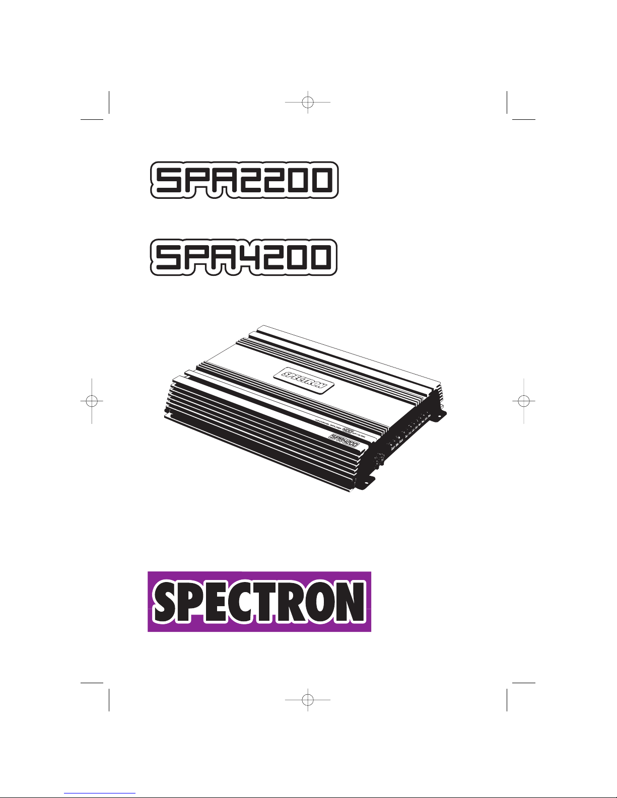
Spectron SPA4200 User manual

2-CHANNEL AMPLIFIER
4-CHANNEL AMPLIFIER
BEDIENUNGSANLEITUNG
OWNER’S MANUAL
SPA2200 4200 Manual 23.05.2002 13:52 Uhr Seite 1

2
SPA2200 4200 Manual 23.05.2002 13:52 Uhr Seite 2

3
INHALT / CONTENTS
TECHNISCHE MERKMALE . . . . . . . . . . . . . . . . . . . . . . . . . . . . . . . . . . . . . . .5
ANSCHLÜSSE & BEDIENUNGSELEMENTE . . . . . . . . . . . . . . . . . . . . . . . . .6-8
INFO'S ZUR INSTALLATION . . . . . . . . . . . . . . . . . . . . . . . . . . . . . . . . . . . . . .9
INFO ZU KABELQUERSCHNITT . . . . . . . . . . . . . . . . . . . . . . . . . . . . . . . . . . .9
MONTAGE DES VERSTÄRKERS . . . . . . . . . . . . . . . . . . . . . . . . . . . . . . . . . .10
VERKABELUNG / ELEKTRISCHER ANSCHLUSS . . . . . . . . . . . . . . . . . . . . . .10
EINSTELLUNGEN AN DER FREQUENZWEICHE . . . . . . . . . . . . . . . . . . . .11-12
DESIGN FEATURES . . . . . . . . . . . . . . . . . . . . . . . . . . . . . . . . . . . . . . . . . . . .13
CONNECTIONS & CONTROLS . . . . . . . . . . . . . . . . . . . . . . . . . . . . . . . . .14-16
INSTALLATION . . . . . . . . . . . . . . . . . . . . . . . . . . . . . . . . . . . . . . . . . . . . . . . .17
GENERAL INFO ABOUT WIRES . . . . . . . . . . . . . . . . . . . . . . . . . . . . . . . . . . .17
AMPLIFIER MOUNTING . . . . . . . . . . . . . . . . . . . . . . . . . . . . . . . . . . . . . . . . .18
CABLE ROUTING . . . . . . . . . . . . . . . . . . . . . . . . . . . . . . . . . . . . . . . . . . . . .18
ADJUSTMENT OF THE INTERNAL CROSSOVER . . . . . . . . . . . . . . . . . . .19-20
TECHNICAL SPECIFICATIONS . . . . . . . . . . . . . . . . . . . . . . . . . . . . . . . . . . .21
LIMITED WARRANTY . . . . . . . . . . . . . . . . . . . . . . . . . . . . . . . . . . . . . . . . . . .22
GARANTIE-BESTIMMUNGEN . . . . . . . . . . . . . . . . . . . . . . . . . . . . . . . . . . . .22
GARANTIEKARTE / WARRANTY CARD . . . . . . . . . . . . . . . . . . . . . . . . . . . . .23
SPA2200 4200 Manual 23.05.2002 13:52 Uhr Seite 3

4
Besten Dank!
Dass Sie sich zum Kauf dieser SPECTRON Car Hifi Endstufe entschieden haben.
Sie besitzen nun ein Produkt, das mit hochwertigen Materialien präzise gefertigt
wurde.
Damit Sie die Wiedergabequalität und Leistungsfähigkeit dieses Verstärkers voll
ausschöpfen können, bitten wir Sie, sich eingehend mit den Features und
Einstellmöglichkeiten dieses Verstärkers vertraut zu machen. Lesen Sie deshalb
diese Bedienungsanleitung sorgfältig durch und bewahren Sie diese Anleitung, die
Kaufquittung und auch die Originalverpackung gut auf.
SPA2200 4200 Manual 23.05.2002 13:52 Uhr Seite 4

5
TECHNISCHE MERKMALE
■MOS-FET NETZTEIL: Die SPA2200 und die SPA4200 sind mit modernen lei-
stungsstarken MOS-FET Netzteilen bestückt, die für eine hohe und stabile
Ausgangsleistung sorgen
■INTEGRIERTE ELEKTRONISCHE FREQUENZWEICHE: Die SPECTRON
Verstärker verfügen über integrierte elektronische Frequenzweichen, mit einer
Flankensteilheit von jeweils 12 dB/Okt. für Hoch- und Tiefpass. Je nach
Verwendungszweck respektive den angeschlossenen Lautsprechersystemen, las-
sen sich am Verstärker Hochpassfilter, Tiefpassfilter oder auch Fullrange Betrieb
wählen
■SAUBERER AUBAU UND KONSTRUKTION: Durch die ausschliessliche
Verwendung von hochwertigen Materialien und der präzisen Fertigung ist die
Betriebssicherheit der SPECTRON Verstärker auch im rauen Einsatz sichergestellt
■INTELLIGENTE SCHUTZSCHALTUNG: Die integrierte Schutzschaltung erkennt
Kurzschlüsse an den Lautsprecherausgängen, Gleichspannung im Ausgangssignal
und überhöhte Betriebstemperatur. Fehlerhafte Betriebszustände führen zum sofor-
tigen Abschalten des Gerätes
■EXTERNE SICHERUNGEN: Für die Absicherung des internen Verstärker-
Netzteiles befindet sich auf der Power-Eingansseite des Verstärkers eine entspre-
chende ATC Sicherung. Diese lässt sich schnell und einfach austauschen
SPA2200 4200 Manual 23.05.2002 13:52 Uhr Seite 5

ANSCHLÜSSE & BEDIENUNGSELEMENTE
FRONT PANEL
1 CINCH-EINGÄNGE 1/2-CH
Eingangsbuchsen für den Anschluss der Cinch Line-Level Ausgänge des
Steuergerätes an den Verstärker
2 CINCH-EINGÄNGE 3/4-CH
Eingangsbuchsen für den Anschluss der Cinch Line-Level Ausgänge des
Steuergerätes an den Verstärker
3 REGLER FÜR DIE EINGANGSEMPFINDLICHKEIT DER KANÄLE 1/2-CH
Eingangsempfindlichkeitsregler der Kanäle 1/2-CH, für die Anpassung an die
Ausgangsspannung des Steuergerätes
4 REGLER FÜR DIE HOCHPASS TRENNFREQUENZ DER KANÄLE 1/2-CH
Regler zum Einstellen der Hochpass-Trennfrequenz an der integrierten
elektronischen Frequenzweiche der Kanäle 1/2-CH
5 SCHIEBESCHALTER FÜR DEN BETRIEBSMODUS DER KANÄLE 1/2-CH
Schiebeschalter für die Festelegung der Arbeitsweise der integrierten elektroni-
schen Frequenzweiche der Kanäle 1/2-CH
6 REGLER FÜR DIE TIEFPASS TRENNFREQUENZ DER KANÄLE 1/2-CH
Regler zum Einstellen der Tiefpass-Trennfrequenz an der integrierten
elektronischen Frequenzweiche der Kanäle 1/2-CH
7 SCHIEBESCHALTER ZUR EINGANGSWAHL
Eingangswahl-Schalter für die Wahl von 2- oder 4-Kanal Input Belegung. D.h. mit
dem Schalter in Position 2-CH lassen sich alle vier Kanäle über ein einzelnes Stereo
Cinchkabel betreiben. Für die Ansteuerung der Endstufe mit zwei Stereo
Cinchleitungen muss der Schalter auf 4-CH stehen!
8 REGLER EINGANGSEMPFINDLICHKEIT DER KANÄLE 3/4-CH
Eingangsempfindlichkeitsregler der Kanäle 3/4-CH, für die Anpassung an die
Ausgangsspannung des Steuergerätes
9 REGLER FÜR DIE HOCHPASS TRENNFREQUENZ DER KANÄLE 3/4-CH
Regler zum Einstellen der Hochpass-Trennfrequenz an der integrierten
elektronischen Frequenzweiche der Kanäle 3/4-CH
10 BETRIEBSMODUS-SCHALTER DER KANÄLE 3/4-CH
Schiebeschalter für die Festelegung der Arbeitsweise der integrierten elektroni-
schen Frequenzweiche der Kanäle 3/4-CH
6
SPA2200 4200 Manual 23.05.2002 13:52 Uhr Seite 6

7
11 REGLER FÜR DIE TIEFPASS TRENNFREQUENZ DER KANÄLE 3/4-CH
Regler zum Einstellen der Tiefpass-Trennfrequenz an der integrierten elektronischen
Frequenzweiche der Kanäle 3/4-CH
12 POWER LED
Grüne "Power" LED; signalisiert den normalen Betriebszustand der Endstufe im
eingeschalteten Zustand
13 PROTECTION LED
Rote "Protection" LED; signalisiert eine generelle Fehlfunktion der Endstufe, wie
z.B. Kurzschluss an den Lautsprecherausgängen, Überhitzung sowie
Gleichspannung an den LS-Ausgängen
L CH
R CH
INPUT GAIN HI PASS
4V 0.2V 40Hz 400Hz
X-OVER
HI FULL LOW
LOW PASS
40Hz 400Hz
POWER
PRT
1 CH
2 CH
3 CH
4 CH
INPUT
GAIN HI PASS
4V 0.2V 40Hz 400Hz
X-OVER
HI FULL LOW
LOW PASS
40Hz 400Hz
POWER
PRT
INPUT
MODE
4V 0.2V 40Hz 400Hz
4CH 2CH
40Hz 400Hz
SPA2200
SPA4200
1345612
13
2 3 4 5 612
131110987
1
SPA2200 4200 Manual 23.05.2002 13:52 Uhr Seite 7

POWER INPUT
GND REM +12V FUSE
SPEAKER OUT
+ L CH - + R CH -
BRIDGE
16 1517 14 18
8
REAR PANEL
14 FUSE
ATC-Sicherungen für die interne Absicherung des Verstärkers gegen Überlastung
und Fehlmanipulation
15 "+ 12V" POWER EINGANGS-TERMINAL
Anschlussterminal für das +12V Hauptstromkabel vom Pluspol der Fahrzeugbatterie
16 "GND" POWER EINGANGS-TERMINAL
Anschlussterminal für das Massekabel von der Chassis-Masse des Fahrzeuges
17 "REM" SCHALTSPANNUNGS-TERMINAL
Anschlussterminal für das Amp-Remote Signal vom Steuergerät
18 LAUTSPRECHER AUSGANGS-TERMINAL
Lautsprecheranschlussterminal für den Anschluss von Lautsprechern, stereo oder
gebrückt
SPA2200
SPA4200
POWER INPUT
GNDREM+12V
FUSE
SPEAKER OUTPUT
BRIDGE
1CH
1CH
2CH 3CH 4CH
BRIDGE
15 161714 18
SPA2200 4200 Manual 23.05.2002 13:52 Uhr Seite 8

9
INFO'S ZUR INSTALLATION
Für die Montage und den Anschluss dieses Verstärkers benötigen Sie entspre-
chendes Montagezubehör, wie z.B. Stromkabel, Cinchkabel, Batterie- und
Masseklemmen etc., welches nicht im Lieferumfang der Endstufe enthalten ist.
Besorgen Sie sich dieses Zubehör im Fachhandel.
Der Verstärker sollte stabil und sicher montiert werden. Achten Sie auf ausreichen-
de Luftzufuhr am Montageort. Die Endstufe darf - weil der Kühlkörper Wärme
abführen muss - nicht völlig "zugebaut" werden. Die Kabelführung (Cinchkabel!)
sowie der Massepunkt am Fahrzeug hat einen entscheidenden Einfluss auf das
störungsfreie Funktionieren Ihrer Anlage!
MONTAGEORT
Suchen Sie einen geeigneten Montageort und stellen Sie eine ausreichende
Belüftung sicher (mindestens 5 cm Freiraum oberhalb der Endstufe und seitlich der
Side-Panels). Dies ist sehr wichtig, weil sich der Verstärker bei Überhitzung
abschaltet. Montageorte mit "unbekanntem Hintergrund" sollten gemieden werden.
Es könnten sich Objekte dahinter befinden, die man besser nicht anbohrt, wie z.B.
ein Benzintank, hydraulische Bremsleitungen, Kabelbäume usw! Der Ort sollte aus-
serdem trocken und nach der Montage noch zugänglich sein - für die
Einstellarbeiten an der Weiche.
INFO ZU KABELQUERSCHNITT
STROMKABEL
Der Stromkabel-Querschnitt sollte - bei einer Gesamtlänge von 5m - 10mm2nicht
unterschreiten. Dies gilt für beide Hauptstromkabel, also +12V und Massekabel.
Falls die Endstufe im Brückenmodus betrieben wird, zwei oder gar drei Endstufen
im Anlagenkonzept enthalten sind, ist für ein Haupt-Stromkabelquerschnitt von
mindestens 16mm2zu sorgen.
Diese Stromkabelstärken garantieren eine problemlose Funktion dieses
Verstärkers, volle Leistungsabgabe und sie verhindern eine Überhitzung! Bei zu
gering gewähltem Batteriekabelquerschnitt kann durch zu starke Erwärmung die
Thermosicherung der Endstufe ansprechen.
CINCHKABEL
Verwenden Sie zum Anschluss dieser SPECTRON Endstufe an Ihr Steuergerät min-
destens doppelt geschirmte Cinchkabel. Die Musiksignalführenden (Cinch-) Kabel
müssen immer soweit wie möglich von allen potentiellen "elektrischen
Störsendern" wie Bordcomputer, Benzinpumpe, Steuerungen, etc. verlegt werden.
MINIMALE LASTIMPEDANZ
Die Kühlkapazität dieser Endstufe und die interne elektronische Schaltung sind für
Lasten von 2 Ohm stereo, oder 4 Ohm mono gebrückt ausgelegt. Vermeiden Sie
den Anschluss von noch tieferen Lastimpedanzen, die Endstufe wird überhitzen
oder kann sogar Schaden nehmen.
SPA2200 4200 Manual 23.05.2002 13:52 Uhr Seite 9

10
MONTAGE DES VERSTÄRKERS
ACHTUNG! Entfernen Sie zu Ihrer eigenen Sicherheit erst das Pluskabel vom
Pluspol der Batterie!
Halten Sie den Verstärker an den gewünschten Ort und markieren Sie mit einem
geeigneten Filzstift die Bohrposition der Befestigungslöcher.
Bohren Sie die angezeichneten Löcher mit einem 2,5 oder 3 mm Bohrer. Drücken
Sie die beigelegten Gummitüllen in die Befestigungslöcher Ihres Verstärkers, der
Verstärker muss immer von der Fahrzeugmasse isoliert befestigt werden! Legen Sie
nun den Verstärker auf die vorgebohrten Löcher und schrauben Sie ihn an.
VERKABELUNG / ELEKTRISCHER ANSCHLUSS
VERLEGEN VON CINCH UND REMOTE KABEL
Verlegen Sie das oder die Cinchkabel und das Remote-Kabel vom Steuergerät zur
Endstufe.
Diese Kabel müssen räumlich getrennt von der Stromzuführung des Verstärkers ein-
gezogen werden. Schliessen Sie das Remote-Kabel an das mit "REM" bezeichnete
Terminal an der Endstufe und an das mit Antenna-Rem. oder Amplifier-Rem.
bezeichnete Kabel Ihres Steuergerätes an.
Anschliessend stecken Sie die Cinchkabel in die Cincheingangsbuchsen des
Verstärker ein. Beachten Sie hierbei die Seitenkennung, d.h. 1-CH ist links, 2-CH ist
rechts, usw.
ANSCHLUSS DER LAUTSPRECHERKABEL
Schliessen Sie nun die Lautsprecherkabel an den Terminals des Verstärkers an.
Beachten Sie hierbei UNBEDINGT die richtige Polung der Lautsprecherkabel am
Terminal (Plus auf Plus, Minus auf Minus). Ziehen Sie die LS-Schraubklemmen satt
an.
VERLEGEN UND ANSCHLUSS DER HAUPT-STROMKABEL
Verlegen Sie das Pluskabel direkt von der Batterie zum Verstärker. Innerhalb der
ersten 30 cm nach dem Pluspolklemmenabgriff muss eine Hauptsicherung ange-
bracht werden. Dies dient zur Absicherung des Pluskabels gegen Kurzschluss auf
Fahrzeug-Masse und nicht der Absicherung der Endstufenelektronik! Verwenden
Sie also eine dem Stromkabelquerschnitt entsprechende Sicherung. Die Sicherung
darf erst nach Abschluss aller Montagearbeiten in den Sicherungshalter gesteckt
werden!
Nun schliessen Sie jetzt dass Minuskabel am Verstärker und am Fahrzeug an.
Versuchen Sie das Massekabel so kurz wie möglich zu halten. Es sollte denselben
Querschnitt wie das Pluskabel besitzen. Achten Sie auf eine perfekt gesäuberte
blanke Metalloberfläche im Fahrzeug. Schlechte Massepunkte sind der Hauptgrund
für später auftretende Störungen, wie Alternatorpfeifen!
Schliessen Sie nun den Stromkreis zum Verstärker durch Einsetzen der
Hauptsicherung. Ihr Autoverstärker sollte nun beim Einschalten des Steuergerätes
durch aufleuchten der grünen Power-LED die Betriebsbereitschaft anzeigen.
SPA2200 4200 Manual 23.05.2002 13:52 Uhr Seite 10

11
Leuchtet die rote Protection-LED auf, ist Ihre Installation fehlerhaft. Gehen Sie alle
vorangehenden Installationsanweisungen nochmals genau durch.
EINSTELLUNGEN AN DER FREQUENZWEICHE
BETRIEBSWAHLSCHALTER
Als Erstes müssen Sie die Arbeitsweise der integrierten elektronischen
Frequenzweiche definieren. Dazu muss der mit X-OVER bezeichnete
Schiebeschalter (zwei Schalter bei der SPA4200) entsprechend dem angeschlos-
senen Lautsprechersystem auf FULL, LOW oder HI gestellt werden. Die Hochpass
(HI) und die Tiefpassweiche (LOW) teilt dem oder den eingesetzten
Lautsprechersystem(en) wie z.B. Subwoofer, Koax- oder Kompo nur den
Frequenzbereich zu, für welchen der Lautsprecher geeignet ist.
HOCHPASS-TRENNFREQUENZ
Die Einstellung der Trennfrequenz des Hochpasses (HI) sorgt für eine elektrische
und mechanische Entlastung der verwendeten Koax oder Komponentensysteme.
Je nach Grösse und Belastbarkeit des Lautsprechers sollte die Hochpass-
Trennfrequenz (HI) im Bereich zwischen 50 bis 150Hz liegen. Diese Einstellung wird
über das HI PASS Potentiometer vorgenommen.
Wenn Sie die Hochpassfrequenz zu tief einstellen, wird der angeschlossene
Satellitenlautsprecher schnell mechanisch überlastet, er verzerrt dann schon bei
mittleren Ausgangspegeln. Bei zu hoch eingestellter Hochpass-Trennfrequenz ist
der Klang im oberen Bassbereich sehr dünn und kraftlos.
TIEFPASS-TRENNFREQUENZ
Bei Betrieb eines Subwoofers (gebrückt oder zwei Einzelschassis stereo) müssen
Sie den X-OVER Schiebeschalter auf LOW stellen, damit der Subwoofer nur Bass-
Signale erhält. Stellen Sie die Trennfrequenz am Tiefpass Potentiometer (LOW
PASS) auf ca. 50 bis 90 Hz. Die effektive Trennfrequenz ist Geschmackssache und
hängt vom Frequenzgang des angeschlossenen Sub's ab, sowie auch von der
Grösse des Fahrzeuginnenraumes.
Anhaltspunkt: Eine zu tiefe Trennfrequenz lässt den Bassbereich kraftlos und
unkonturiert wirken. Eine zu hohe Trennfrequenz bewirkt ein Dröhnen des
Bassbereichs.
ANPASSUNG DER EINGANGSEMPFINDLICHKEIT
Bevor Sie mit der Anpassung der Eingangsempfindlichkeit(en) anfangen, müssen
erst alle Klangregler, wie z.B. Bass, Treble, Fader/Balance und Loudness in ihre
jeweilige OFF oder Mittel (Neutral) Position gebracht werden.
Wenn ein Subwoofersystem in der Gesamtanlage enthalten ist, muss immer dessen
Eingangsempfindlichkeit als erstes angepasst werden. Die Anpassung aller weite-
ren (Satelliten)Lautsprecher erfolgt nach der Einstellung des Subwoofer
Referenzpegels!
SPA2200 4200 Manual 23.05.2002 13:52 Uhr Seite 11

12
Drehen Sie nun das Input GAIN Potentiometer vom betreffenden Subwoofer-
Kanalpaar im Gegenuhrzeigersinn auf die Minimumposition. Schalten Sie das
Steuergerät ein und stellen Sie den Lautstärkeregler auf ca. 3/4 der
Maximallautstärke. Benutzen Sie für die Empfindlichkeits-Einstellung ein gut aufge-
nommenes, dynamikreiches Musikstück.
Drehen Sie den Input GAIN Regler vom Subwoofer-Kanalpaar am Verstärker lang-
sam im Uhrzeigersinn auf, bis Sie gerade die Verzerrungsgrenze im Bassbereich
erreichen.
Stellen Sie jetzt die Lautstärke an Ihrem Steuergerät auf einen mittleren Wert
zurück, und drehen Sie den GAIN Regler vom Kanalpaar der Frontsysteme (z.B.
Satelliten in den Vordertüren) langsam auf. "Dosieren" Sie die Lautstärke des vor-
deren Lautsprechersystems so zum Bass hinzu, dass sich ein ausgewogener und
basskräftiger Klang einstellt. Wenn mit dem SPECTRON Verstärker kein Subwoofer
angesteuert wird, muss das Lautsprechersystem, welches am lautesten spielen
soll, zuerst eingestellt werden - danach folgen wenn vorhanden, weitere
Kanalpaare.
SPA2200 4200 Manual 23.05.2002 13:52 Uhr Seite 12

13
Congratulations!
And thank you for choosing this SPECTRON car audio power amplifier! You now
own a car audio amplifier of high quality, manufactured with high quality parts and
advanced assembly methods.
To maximize the performance of this amplifier, we recommend that you acquaint
yourself thoroughly with all technical features and the control options of this power
amplifier. Therefore, read this manual carefully, before attempting the installation of
this amplifier unit. Please retain this manual, the original packing and your purcha-
sing / installation receipts for future reference.
DESIGN FEATURES
■MOSFET POWER SUPPLY: This SPECTRON amplifier features a PWM modula-
ted MOS-FET power supply, to give you high and stable power output
■INTEGRATED ELECTRONIC ACTIVE CROSSOVER: SPECTRON amplifiers
feature integrated electronic crossovers with independently selectable highpass
and lowpass filtering, as well as fulllrange loop through. All internal active filters fea-
ture crossover slope rates of 12 dB/octave
■CLEAN DESIGN AND CONSTRUCTION: Only good electrical and electronic
components are used in SPECTRON amplifiers. Precision assembly and a final ins-
pection guarantee flawless performance of this SPECTRON amplifier
■ADVANCED PROTECTION CIRCUITRY: The protection circuitry safe-guards
the amplifier from short-circuits at the speaker outputs, DC offset voltage at the
outputs and overheating of power electronics
■EXTERNAL FUSE: The input side-panel of this amplifier is equipped with an ATC
type fuse holder(s), for a fast and convenient exchange of blown fuses
SPA2200 4200 Manual 23.05.2002 13:52 Uhr Seite 13

14
CONNECTIONS & CONTROLS
FRONT PANEL
1 RCA INPUTS 1/2-CH
Low-level stereo RCA inputs for connection with the line-outs of the head-unit
2 RCA INPUTS 3/4-CH
Low-level stereo RCA inputs for connection with the line-outs of the head-unit (only
for SPA2200)
3 INPUT GAIN CONTROL 1/2-CH
Input gain control potentiometer for 1/2-CH amplifier section, to match the output
voltage of the head-unit's RCA line-outs to the amplifier input section
4 HIGH PASS FREQUENCY CONTROL 1/2-CH
Control potentiometer for the highpass crossover frequency adjustment of the 1/2-
CH channel section of the amplifier
5 OPERATION MODE SWITCH 1/2-CH
Slide switch to select the operation mode of the electronic crossover driving 1/2-
CH channel section of the amplifier
6 LOW PASS FREQUENCY CONTROL 1/2-CH
Control potentiometer for the lowpass crossover frequency adjustment of the 1/2-
CH channel section of the amplifier
7 INPUT SELECTOR SWITCH
Slide switch to select either a 2-channel or a 4-channel RCA input signal, to drive
the SPA4200. This switch must be set to its 2-CH position if the amp shall be dri-
ven by one stereo RCA interconnect only, and set to 4-CH when driven by two ste-
reo RCA interconnects respectively
8 INPUT GAIN CONTROL 3/4-CH
Input gain control potentiometer for 3/4-CH amplifier section, to match the output
voltage of the head-unit's RCA line-outs to the amplifier input section
9 HIGH PASS FREQUENCY CONTROL 3/4-CH
Control potentiometer for the highpass crossover frequency adjustment of the 3/4-
CH channel section of the amplifier
10 OPERATION MODE SWITCH 3/4-CH
Slide switch to select the operation mode of the electronic crossover driving the
3/4-CH channel section of the amplifier
SPA2200 4200 Manual 23.05.2002 13:52 Uhr Seite 14

11 LOW PASS FREQUENCY CONTROL 3/4-CH
Control potentiometer for the lowpass crossover frequency adjustment of the 3/4-
CH channel section of the amplifier
12 POWER LED
Green "operation" LED, lit when amp is turned ON, signaling correct operation
13 PROTECTION LED
Red "protection" LED, signaling faulty speaker connections or general malfunction
of the amplifier
15
L CH
R CH
INPUT GAIN HI PASS
4V 0.2V 40Hz 400Hz
X-OVER
HI FULL LOW
LOW PASS
40Hz 400Hz
POWER
PRT
1 CH
2 CH
3 CH
4 CH
INPUT
GAIN HI PASS
4V 0.2V 40Hz 400Hz
X-OVER
HI FULL LOW
LOW PASS
40Hz 400Hz
POWER
PRT
INPUT
MODE
4V 0.2V 40Hz 400Hz
4CH 2CH
40Hz 400Hz
SPA2200
SPA4200
1345612
13
2 3 4 5 612
131110987
1
SPA2200 4200 Manual 23.05.2002 13:52 Uhr Seite 15

16
REAR PANEL
14 FUSE
An ATC fuses for protection of the amplifier electronics against overload or wrong
operation
15 POWER INPUT TERMINAL "+ 12 V"
Terminal to connect the amplifier to the positive +12V pole of the car battery
16 POWER INPUT TERMINAL "GND"
Terminal to connect the amplifier to the negative or ground pole of the vehicle
17 REMOTE INPUT TERMINAL
Terminal to connect the amplifier to the automatic (remote) turn-on / turn-off lead of
the head unit
18 SPEAKER OUTPUT TERMINALS
Output terminal to connect the speakers in stereo or bridged mode to the amplifier
POWER INPUT
GND REM +12V FUSE
SPEAKER OUT
+ L CH - + R CH -
BRIDGE
16 1517 14 18
SPA2200
SPA4200
POWER INPUT
GNDREM+12V
FUSE
SPEAKER OUTPUT
BRIDGE
1CH
1CH
2CH 3CH 4CH
BRIDGE
15 161714 18
SPA2200 4200 Manual 23.05.2002 13:52 Uhr Seite 16

INSTALLATION
To install and connect this SPECTRON amplifier, you have to buy additional acces-
sories like power cables, RCA interconnects, fuse holders, etc. To obtain best per-
formance and power output, it is recommended to use good quality accessory
materials only. Furthermore, consider safe mounting of the amp, sufficient ventila-
tion, convenient accessibility of all the side panel controls, etc.
Please note that - because of possible interference problems with the existing car
electrics and electronics - especially the routing of the RCA signal cables and the
chassis ground connection are absolutely crucial.
MOUNTING LOCATION
Check the suitability of your preferred amplifier location carefully, before you start
installation attempts. Once you found a convenient location, bolt the amp unit in a
position that ensures free air flow.
And always choose a place where you can be sure nothing gets damaged behind
or below the panel, by drilling the holes for the amplifier mounting screws. After
installation, there should be a clearance of at least 5cm to all sides, so the side
panel can be reached for further adjustments to the electronic crossover.
GENERAL INFO ABOUT WIRES
MAIN POWER CABLE CROSS SECTION
The minimum power cable cross-section for this SPECTRON amplifier is 10mm2. If
you intend to bridge the amplifier, and if you run two or more amplifiers in your car
audio system, the minimum power cable cross section shall be 16mm2.
These recommendations guarantee trouble-free operation of your amp, giving you
full power output. Using main power cables with smaller cross sections will result
in over-heating of the amplifier circuitry, elevated distortions and they can also
cause the thermal protection circuitry to trigger, and shut-down the amplifier!
RCA INTERCONNECTS
Use at least double shielded RCA interconnect cables. Keep in mind, that the RCA
interconnects should always be kept far away from any potential sources of elec-
trical interferences, for example avoid to cross electronic vehicle management
systems (engine computers, relays etc.) fuel pumps, wiring harnesses etc.!
MINIMUM SPEAKER IMPEDANCES
The internal circuitry and the heat dissipation capacity of the amplifier's heatsink
has been designed to cope with 2 ohm impedance loads. Therefore, you can drive
4 to 2 ohm satellite speaker systems - or 4 ohm subwoofer systems in bridged ope-
ration mode. Do NOT operate this amplifier bridged into 2 ohm loads!!!!
17
SPA2200 4200 Manual 23.05.2002 13:52 Uhr Seite 17

18
AMPLIFIER MOUNTING
Attention! For your own safety, disconnect the positive battery terminal (+12V)
or remove the main fuse of the 12V power cable, before you start any wiring
work!
Once the location where the amplifier will be mounted is found, use the unit as a
template and mark the mounting holes with pencil or felt-tip marker. Pilot-drill the
these holes, using a 2,5mm or 3mm drill bit on your power drill. Insert the supplied
rubber washers into the mounting holes of the amp. This amplifier must be moun-
ted isolated from the vehicle's chassis ground. Bolt the unit in place with the sup-
plied self tapping screws.
Important! The amplifier, or parts of it must never touch or have contact with metal
parts of the vehicle, since electrical ground-loops always result in loud hum noise!
CABLE ROUTING
RCA INTERCONNECTS AND REMOTE WIRING
Run the RCA interconnects and the remote lead from the head-unit to the amplifier.
Note that RCA interconnects must be routed completely separate from the main
power cable. Connect the remote (turn on/turn off) lead to the REM input terminal
of the amplifier and to the remote output lead of your head-unit. Now you can plug
in the RCA interconnects to the line outputs of your head-unit and to the RCA
inputs of the amplifier. Pay attention when connecting the RCA cables to the amp:
The left line out must be connected to 1CH input, the right line out must be connec-
ted to 2CH input.
For the SPECTRON amplifier model SPA4200, you should now set the input mode
selector switch to the corresponding position. Choose 2-CH when the amplifier is
fed with one stereo RCA interconnect - or set the slide switch to its 4-CH position
if the amp is driven by two pairs of RCA interconnects.
LOUDSPEAKER WIRE ROUTING
Once the speaker cables have been routed, turn loose the speaker terminal screws
and - after inserting the stripped speaker cables - re-tighten the screws. Always
maintain correct polarity ("+" to "+"; "-" to "-").
MAIN POWER CABLES
Run the positive main power cable ("+12 V") directly from the positive terminal of
the car battery to the amplifier. For protection of your car audio system against
electrical short cuts and fire hazards, you must insert a fuse holder within the first
30cm of the positive main power cable. The applicable fuse value must be matched
to the limitations of your main power cable cross section!
Connect the ground cable to the ground terminal input of your amplifier and to a
rust free ground point in your vehicle. Keep the ground cable ("-12V") as short as
possible. The ground power cable must have the same cross-section as the posi-
tive power cable.
SPA2200 4200 Manual 23.05.2002 13:52 Uhr Seite 18

Tighten up both power input terminals, and double check for perfect fit of both main
cable leads!
ADJUSTMENT OF THE INTERNAL CROSSOVER
OPERATION MODE
Before you power up your amplifier, you must select and set the appropriate ope-
ration mode first. The OPERATION MODE is set, depending on the speaker system
connected to the corresponding channel pair of the amplifier. For example select
highpass (HI), if the speaker system driven by the corresponding channel pair is a
component-, coaxial- or triaxial- type. Or else, set the operation mode switch to
lowpass (LOW), if the channel pair is intended to drive a subwoofer system.
Highpass or lowpass filtering allows the connected loudspeakers to work in the fre-
quency band they can reproduce best.
HIGHPASS CROSSOVER FREQUENCY ADJUSTMENT
For satellite speakers, set the operation mode slide switch to its "HI" position and
then adjust the highpass crossover frequency point, using the "HI PASS" crossover
frequency control potentiometer.
Depending on the effective cone surface and the power handling of the installed
'satellite' speaker system, it is recommended to find a suitable high-pass cross-
over frequency point between 50 to 150Hz. This setting must be determined by ear,
since it represents a compromise where either midbass reproduction or power
handling has to be sacrificed, depending on what is more important for you!
Note: If the highpass crossover frequency point for a given satellite system is set
too low, the speakers will be mechanically overdriven already by low volume levels.
LOWPASS CROSSOVER FREQUENCY ADJUSTMENT
Set the operation mode switch to its "LOW" position, to drive a subwoofer system.
The LOW PASS cut-off frequency point must be played by ear, i.e. since this cros-
sover frequency point is mostly a matter of personal taste. As a rule of thumb, set-
tings in a range between 60 to 90 Hz will render best sonic results. In general, set-
ting the lowpass crossover frequency point too low, will result in a weak and muddy
sounding bass, while setting this crossover frequency too high will result in a 'boo-
ming' bass sound and reduced low end extension.
INPUT GAIN CONTROL ADJUSTMENT
Before you start, you MUST set all tone controls (Bass, Mid, Treble, Loudness etc.)
and the fader on the head unit to their neutral or center positions.
Now turn all input gain controls of the installed amplifiers anti-clockwise to their
minimum positions and ALWAYS start with the channel pair, that drives the subwo-
ofer system (if applicable!).
19
SPA2200 4200 Manual 23.05.2002 13:53 Uhr Seite 19

20
SUBWOOFER CHANNEL
Set the volume control of your head-unit to approximately 3/4 of full volume, while
playing a dynamic piece of music. Slowly increase the input gain control of the
channel pair, that drives the subwoofer(s), by turning the input GAIN control clock-
wise until you can just about hear distorted sounds coming out of your subwoofer
system. Reduce the main volume level on your head-unit to a medium listening
level.
SATELLITE CHANNELS
Slowly increase the input gain control of the remaining channel pair, for example the
section that drives the satellite system, by turning the GAIN control clockwise until
you reach a good tonal balance, with a slight emphasis of the bass range. Turn up
the input gain control of all remaining channel pairs - if there are any - to reach a
good homogeneous balance between all speaker pairs installed in your vehicle.
Done!
SPA2200 4200 Manual 23.05.2002 13:53 Uhr Seite 20
This manual suits for next models
1
Table of contents
Languages:
Other Spectron Amplifier manuals