Spectrum Digital AppBox D21 User manual

AppBox D21 System User’s Guide 1 AppBox
Specializes in
designing with
Microchip
products
AppBox D21
System User’s
Guide
AppBox D21 System User’s Guide 2 AppBox
Notice !
Spectrum Digital, Inc (SDI) provides the enclosed product under the following conditions:
The user/customer assumes all responsibility and liability for the proper use, storage, and safe handling
of the product. Further, the user indemnifies SDI from all claims arising from the use, installation, storage,
and handling of the product. Due to the flexibility and open construction of the product, it is the user’s
responsibility to take all appropriate precautions with regard to powering, attachment of cables,
connection to other equipment, and electrostatic discharge.
Except to the extent of the indemnity set forth above, neither party shall be liable to the other for any
indirect, special, incidental, or consequential damages.
SDI assumes no liability for applications assistance, customer product design, system and software
performance, or infringements of patents or services described herein.
No license is granted under any patent right or other intellectual property right of SDI covering or relating
to any machines, process, software, or combination in which such SDI products or services might be or
are used.
SDI currently deals with a variety of customers for products, and therefore our arrangement with the
reseller, customer, or user is not exclusive.
Please refer to the product web page on the SDI web site for warranty period.
The warranty and return policy are described on the SDI web site.
Mailing address:
Spectrum Digital, Inc
PO Box 1559
Sugar Land, TX. 77487-1559
Web site: www.spectrumdigital.com
Sales: [email protected]
Support: support@spectrumdigital.com
Copyright Spectrum Digital Inc, © 2020
519108-4001

AppBox D21 System User’s Guide 3 AppBox
Table of Contents
Section Title Page
1.0 Introduction . . . . . . . . . . . . . . . . . . . . . . . . . . . . . . . . . . . . . . . . . . . . . . . . 4
1.1 AppBox D21 Features . . . . . . . . . . . . . . . . . . . . . . . . . . . . . . . . . . . . . . . . . . 4
1.2 What’s Included In The AppBox D21 . . . . . . . . . . . . . . . . . . . . . . . . . . . . . . 5
1.3 AppBox D21 Front Panel . . . . . . . . . . . . . . . . . . . . . . . . . . . . . . . . . . . 5
1.4 AppBox D21 Accessories . . . . . . . . . . . . . . . . . . . . . . . . . . . . . . . . . . . 5
1.5 AppBox D21 Communication Expansion . . . . . . . . . . . . . . . . . . . . . . . 6
1.6 AppBox D21 Software Development Tools . . . . . . . . . . . . . . . . . . . . . . . 6
2.0 Installation . . . . . . . . . . . . . . . . . . . . . . . . . . . . . . . . . . . . . . . . . . . . . . . . 7
2.1 Attaching Power to the AppBox D21 . . . . . . . . . . . . . . . . . . . . . . . . . . . . . 7
2.2 Installation of AppIO Modules . . . . . . . . . . . . . . . . . . . . . . . . . . . . . . . . . . . . 8
2.3 Attachment of the Distribution Box to the AppBox D21 . . . . . . . . . . . . . . . . . 9
2.4 Installation of Atmel-ICE . . . . . . . . . . . . . . . . . . . . . . . . . . . . . . . . . . . . 10
3.0 Interfaces . . . . . . . . . . . . . . . . . . . . . . . . . . . . . . . . . . . . . . . . . . . . . . . . . 11
3.1 Connectors . . . . . . . . . . . . . . . . . . . . . . . . . . . . . . . . . . . . . . . . . . . . . . . . . 12
3.1.1 J1, Power Connector . . . . . . . . . . . . . . . . . . . . . . . . . . . . . . . . . . . . . . . . . . . 13
3.1.2 J2, RS485 Connector . . . . . . . . . . . . . . . . . . . . . . . . . . . . . . . . . . . . . . . . . . 14
3.1.3 J3, USB Connector . . . . . . . . . . . . . . . . . . . . . . . . . . . . . . . . . . . . . . . . . . . 15
3.1.4 J6, Cortex-M Debug Connector . . . . . . . . . . . . . . . . . . . . . . . . . . . . . . . . . . . . 15
3.1.5 AppIO Module Connectors . . . . . . . . . . . . . . . . . . . . . . . . . . . . . . 16
3.1.5.1 EXT1, AppIO Module 1 Connector . . . . . . . . . . . . . . . . . . . . . . . . . . . . . . 17
3.1.5.2 EXT2, AppIO Module 2 Connector . . . . . . . . . . . . . . . . . . . . . . . . . . . . . . 18
3.1.5.3 EXT3, AppIO Module 3 Connector . . . . . . . . . . . . . . . . . . . . . . . . . . . . . . 19
3.2 Jumpers . . . . . . . . . . . . . . . . . . . . . . . . . . . . . . . . . . . . . . . . . . . . . . . . . . 20
3.3 Switches . . . . . . . . . . . . . . . . . . . . . . . . . . . . . . . . . . . . . . . . . . . . . . . . . . 22
3.4 LEDs . . . . . . . . . . . . . . . . . . . . . . . . . . . . . . . . . . . . . . . . . . . . . . . . . . . . . . . . 23
3.5 Test Points . . . . . . . . . . . . . . . . . . . . . . . . . . . . . . . . . . . . . . . . . . . . . . . . . 23
4.0 Physical Characteristics . . . . . . . . . . . . . . . . . . . . . . . . . . . . . . . . . . . . . 23
5.0 Mechanical Information . . . . . . . . . . . . . . . . . . . . . . . . . . . . . . . . . . . . . 24
6.0 Schematics . . . . . . . . . . . . . . . . . . . . . . . . . . . . . . . . . . . . . . . . . . . . . . . . . 24
AppBox D21 System User’s Guide 4 AppBox
1.0 Introduction
This document describes the features of the AppBox D21. The AppBox D21 is designed to be used in an
industrial environment with a USB, or RS-485 interface and provide flexible, modular I/O (AppIO) for specific
applications. These AppIO Modules allow customized solutions to be integrated for a wide variety of
applications that need to go into a USB or RS-485 communications environment.
1.1 Features
This AppBox D21 has the following features:
Atmel ATSAMD21J18A processor (ARM Cortex-M0+), maximum frequency 48 MHz.
Operates on +12 to +24 volts DC, uses less than 500 Ma. at +12V
USB interface for industrial computer systems
RS485 communications for industrial systems
Communication interface expansion via Distribution Box (sold separately)
Modular I/O expansion via up to three (3) AppIO Modules, Atmel X PLAINED compatible
Fully enclosed system with knock out panels for AppIO Modules (sold separately)
Convenient enclosure mounting holes
Vented enclosure for cooling
Front panel push button switch
Front panel programmable LED
Atmel-ICE debug header present for development
Operates 0 - +70C
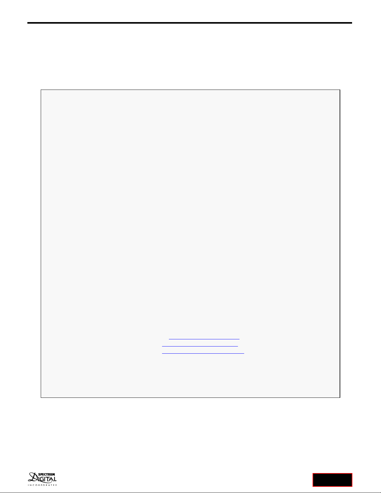
D21 CPU BOARD AppIO
Module #1
AppIO
Module #3
AppIO
Module #2
RS485
Power
+12-24 VDC Interface #3
Interface #1
Interface #2
User Defined
AppBox D21 Block Diagram
LED
Push
Button
Switch Comms
Select
Switch
ATSAMD21J18A
uP
USB
Atmel-ICE
Header
LED1
SW1
J2
J1
J3
EXT1
EXT2
EXT3

AppBox D21 System User’s Guide 5 AppBox
1.2 What’s Included In the AppBox D21
The Spectrum Digital AppBox D21 product (Part/SKU #: 703910-0001) includes:
AppBox D21 in anti-static bag
Terminal block header for power input
Product information card
NOTE: This product does not include any software or drivers. Development tools (Atmel-ICE and
Software code generation suite) can be obtained from Microchip/Atmel at:
https://www.microchip.com/development-tools/.
1.3 AppBox D21 Front Panel
The features of the front panel on the AppBox D21 are shown in the figure below:
1.4 AppBox D21 Accessories
The following accessories for the AppBox D21 can be ordered from Spectrum Digital or authorized resellers:
Accessory Description Part/SKU Number
AppBox Power Supply with cable,
110/220 VAC to 12 VDC, 1.5A 703925-0001
Distribution Box 703924-0001
AppBox Cable 703923-0001
RS485 cable 703917-0001
USB-RS485 cable 703914-0001
SW1 J1
J2LED1 AppBox D21 Front Panel
USB
AppBox D21 System User’s Guide 6 AppBox
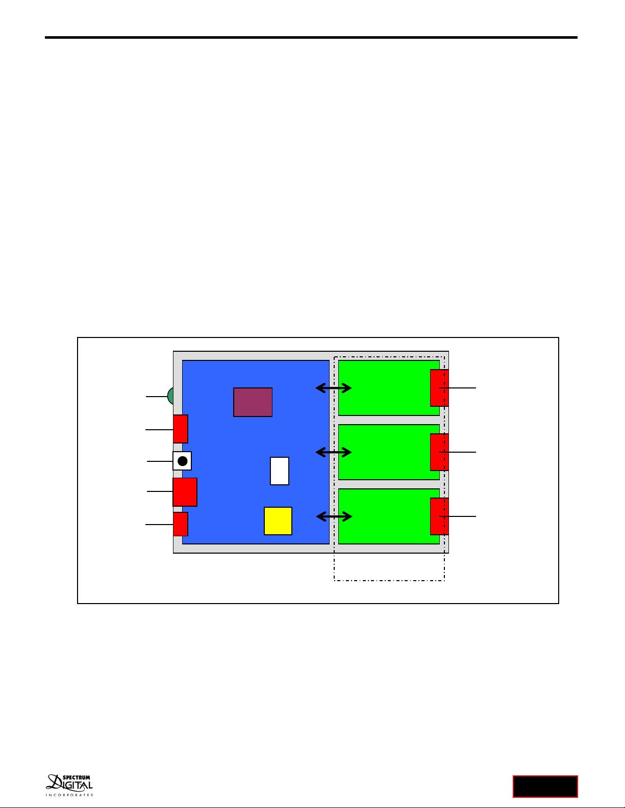
1.5 AppBox D21 Communication Expansion
The J2 connector on the AppBox D21 presents multiple communication interfaces. The standard factory
cables only support one interface at a time. To have access to multiple communication interfaces a
Distribution Box (Part/SKU #: 703924-0001) and AppBox cable (Part/SKU #: 703923-0001) are required.
The Distribution Box expands the J2 connector to four (4) images of the AppBox D21 J2 connector. The
AppBox cable bridges all signals on the AppBox D21 J2 connector to a connector on the Distribution Box.
Be aware that one of the Distribution Box connectors will be used for the AppBox bridging cable leaving
3 connectors to be used for communication interfaces. All cables that can plug into the J2 connector on the
AppBox D21 can plug into the Distribution Box.
The user should enable all interfaces they want to use with the Distribution Box by setting the switch positions
on Switch SW2, position 1. See section 3.3.
The AppBox D21 and Distribution Box system configuration is shown in the figure below:
1.6 AppBox D21 Software Development Tools
The AppBox D21 is compatible with the software and hardware development tools from Microchip/Atmel.
These tools are described on the Microchip/Atmel website:
https://www.microchip.com/development-tools/
These tools include the following:
Editor
Compiler/assembler/linker
Libraries
Operating System
Debugger
JTAG Emulator
RS485
RS485
RS485
AppBox D21 with Distribution Box
Distribution Box
AppBox D21
J2 Connector
AppBox Cable

AppBox D21 System User’s Guide 7 AppBox
2.0 Installation
2.1 Attaching Power to the AppBox D21
Power can be provided to the AppBox D21 by two different means; the AppBox power supply with cable
(Part/SKU #: 703925-0001), or wiring the 2 position terminal block header (included with AppBox D21) that
plugs into the D21 CPU Board’s power input connector. See the figure below.
Listed below are the steps to install the terminal block header power connector (included in kit) into the
AppBox D21.
1. Cut 2 pieces of wire (preferably 1 red for positive-VIN, 1 black for negative-DGND) to the desired
length for your application. This wire should be 22 gauge or heavier
2. Strip ¼ inch (6-7 mm) of insulation from one end of each wire.
3. Position the terminal block header on a flat surface with the key stubs up and away from you. See
the figure below.
4. Insert the negative/DGND wire (black) into the left wire hole and tighten the screw.
5. Insert the positive/VIN wire (red or black with strip) into the right wire hole and tighten the screw.
6. The terminal header should look like the figure below.
7. Pull/tug on the wires to insure they are secure in the terminal block.
Terminal Block Header
AppBox Power Connector
Positive
VIN
Negative
DGND
Wired Terminal Block Header
Positive
VIN
Negative
DGND
Screw
Screw

AppBox D21 System User’s Guide 8 AppBox
8. Attach the loose end of the wires to a +12 – 24 VDC power source. Be sure of the polarity. This
power source should supply at least 1 amp of current. This requirement will vary
depending on the current requirements of the C21 CPU Board and the AppIO Modules.
9. Turn on the power source.
10. With a multi-meter or oscilloscope measure the voltage at the terminal block header to verify
+12 -24 VDC is present. Place the meter/scope probes on the 2 screws to measure.
11. Turn off the power source
12. Insert the terminal block header into the power input of the AppBox D21.
13. Turn on the power source.
2.2 Installation of AppIO Modules
Listed below are the steps to install AppIO Modules in the AppBox D21:
1. Remove ALL power to the AppBox enclosure
2. Remove all interface connections attached to the installed AppIO Modules
3. Remove the USB/RS-485 cables to the D21 processor board
4. Turn the AppBox over and remove the 2 screws from the bottom of the enclosure as shown
below
5. Turn the AppBox back over (label showing) and lift the top off the enclosure being careful not to
lose the knockout panels
6. If necessary remove one or more existing AppIO Modules and associated knockout panels by
unscrewing the 2 screws
7. Plug the new AppIO Module(s) into EXT1, EXT2, or EXT3 on the D21 CPU Board
Screws
A
pp
Box Bottom Screw Locations
A
pp
IO Module
A
ttached to D21 CPU Board
D21 CPU
Board
AppIO Knockout
Panel
AppIO Module
Screw
Screw

AppBox D21 System User’s Guide 9 AppBox
8. Insert the included knock out panel associated with this AppIO Module
9. Insert and tighten the 2 screws for the AppIO Module
10. Insert the knock out panels in any unused positions
11. Place the cover back over the D21 processor board and AppIO Modules
12. Insert the 2 screws back in and tighten until snug, do not over tighten/strip the screws
13. Re-attach the USB/RS-485 connections to the processor board
14. Re-attach all interface connections to the AppIO Modules
15. Apply power to the AppBox D21
2.3 Attachment of Distribution Box to the AppBox D21
Listed below are the steps to attach the Distribution Box (Part/SKU #: 903924-0001) to the AppBox D21:
1. Remove ALL power to the AppBox D21 enclosure
2. Remove any communication cables from the J2 connector on the AppBox D21
3. Plug one end of the AppBox cable (Part/SKU #: 703923-0001) into the J2 connector on the
AppBox D21
4. Plug the other end of the AppBox cable into one of the connectors on the Distribution Box
5. Plug the desired communication cables into the Distribution Box
6. Make all other connections before powering
7. Apply power to the AppBox D21
A
pp
Box D21 with A
pp
IO Module Installed
AppIO Module
Connector
AppIO Knockout
Panel
A
pp
Box D21 Connected to Distribution Box
AppBox
AppBox Cable
Distribution Box

AppBox D21 System User’s Guide 10 AppBox
2.4 Installation of Atmel-ICE emulator
Listed below are the steps to install Atmel-ICE emulator:
1. Remove ALL power to the AppBox D21 enclosure
2. Remove all interface connections attached to the AppIO Modules
3. Remove the USB/RS-485 connections to the processor Module
4. Turn the AppBox over and remove the 2 screws from the bottom of the enclosure as shown
below
5. Turn the AppBox back over (label showing) and lift the top off the enclosure being careful not to
lose the knockout panels
6. Plug the emulator end of the ribbon cable into the “SAM” Port on the emulator
7. Plug in the Atmel-ICE debug into connector J6 on the AppBox D21 CPU board. Visually inspect
the connection to insure all the board pins are in the female cable connector.
8. Re-attach the USB/RS-485 connections to the processor board
9. Re-attach all interface connections to the AppIO Modules
10. Apply power to the AppBox D21
11. Start debug session on the host computer
Screws
A
pp
Box Bottom Screw Locations
D21 CPU Board
Atmel-ICE Attached to A
pp
Box D21 CPU Board
Atmel-ICE
J6 Connector
RED Wire
SAM Port
AppBox D21 System User’s Guide 11 AppBox
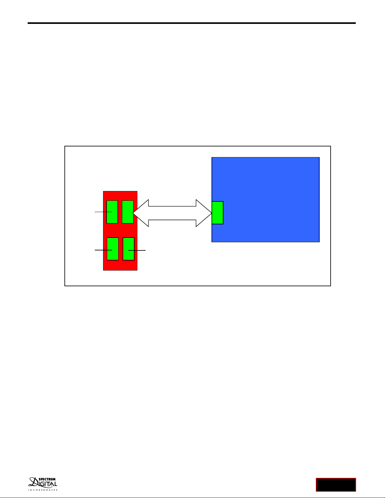
3.0 Interfaces
This section describes the interfaces on the AppBox D21 CPU Board. These interfaces include the
connectors, jumpers, switches, LEDs, and test points.
The location of each of these interfaces is shown in the figure below:
SW1
SW2
J1
EXT1
EXT3
EXT2
J6
J2
TP2 TP3TP1
LED1
J3
AppBox D21 CPU Board Interfaces

AppBox D21 System User’s Guide 12 AppBox
The table below lists all the interfaces on the AppBox D21 CPU Board.
AppBox D21 CPU BOARD INTERFACES
INTERFACE NAME TYPE OF INTERFACE
J1 Connector for power input
J2 Connector for RS-485
J3 Connector for USB
J6 Connector for header 5x2
Cortex-M Debug
EXT1 Connector to AppIO Module
EXT2 Connector to AppIO Module
EXT3 Connector to AppIO Module
JP1 SMT jumper (bottom)
JP2 SMT jumper (bottom)
JP3 SMT jumper (bottom)
JP4 SMT jumper (bottom)
JP7 SMT jumper (bottom)
JP8 SMT jumper (bottom)
JP9 SMT jumper (bottom)
JP10 SMT jumper (bottom)
JP11 SMT jumper (bottom)
SW1 Pushbutton switch
SW2 4 position DIP switch
LED1 Green LED
TP1 Test point
TP2 Test point
TP3 Test point
3.1 Connectors
The following section describes the connectors on the AppBox D21 CPU Board.
INTERFACE NAME TYPE OF INTERFACE MATING CONNECTOR
J1 Connector for power input
Amphenol Anytek
Terminal block, 2 pos
TJ2031530000G
TS02315A0000G
J2 Connector for RS-485
10 position, 2 x 5
Molex 10 Position Rectangular
Housing Connector Receptacle
Natural 0.165" (4.20mm)
0039012100, 0039000038
J3 Connector for USB ??
J6 Connector for header 5x2
Cortex-M Debug Cortex-M Debug tail
EXT1 Connector to AppIO Module #1,
20 position, 2 x 10
EXT2 Connector to AppIO Module #2,
20 position, 2 x 10
EXT3 Connector to AppIO Module #3,
20 position, 2 x 10
AppBox D21 System User’s Guide 13 AppBox
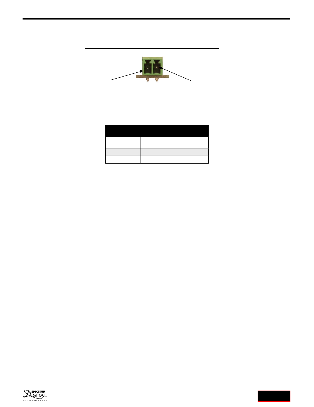
3.1.1 J1, Power Connector
This section describes J1, he power connector. Shown below is a physical diagram of the J1 connector.
The following table shows the signals present on the J1 connector.
J1, Power Connector
Pin number Signal name
1 DGND
2 VIN, (+12-24 VDC)
Pin 1, DGND Pin 2, +12-24V
J1, Power Connector
(card edge view)
AppBox D21 System User’s Guide 14 AppBox
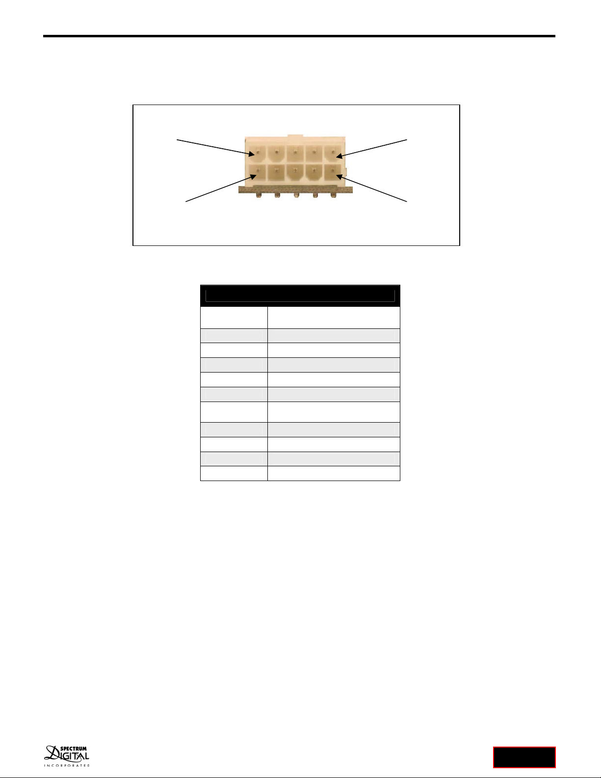
3.1.2 J2, RS485 Connector
This section describes J2, the RS485 connector. The diagram below shows the physical diagram of the J2
connector.
The following table shows the signals present on the J2 connector.
J2, RS485 Connector
Pin number Signal name
1 RS485_A
2 RS485_B
3 DGND
4 No Connect
5 No Connect
6 JP7, VDD_V5 if JP7 shorted,
No connect if JP7 open
7 DGND
8 No Connect
9 No Connect
10 DGND
Pin 5, No connect J2, RS485 Connector
Pin 6, Pin 2, JP7Pin 10, DGND
Pin 1, RS-485
_A
(card edge view)

AppBox D21 System User’s Guide 15 AppBox
3.1.3 J3, USB Connector
The following table shows the signals present on the J3 connector. The J3 connector is a female USB
connector.
3.1.4 J6, Cortex-M Debug Connector
The following table shows the signals present on the J6 connector.
J6, Cortex-M Debug Connector
Pin number Signal name
1 VDD_3V3, +3.3 volts
2 PA31_SWDIO
3 DGND
4 PA30_SWCLK
5 DGND
6 No Connect
7 No Connect
8 No Connect
9 DGND
10 RESETn
J3, USB Connector
Pin number Signal name
1 VBUS / Pin 5, U6
2 D- / PA24_USB_DM, Pin 1, U6, IO1
3 D+ / PA25_USB_DP, Pin 3, U6, IO2
4 ID / Pin 4, U6, IO3
5 DGND
6 SHIELD1 / DGND via cap
7 SHIELD2 / DGND via cap
8 SHIELD3 / DGND via cap
9 SHIELD4 / DGND via cap
10 SHIELD5 / DGND via cap
11 SHIELD6 / DGND via cap
AppBox D21 System User’s Guide 16 AppBox
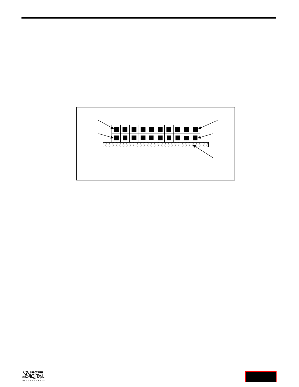
3.1.5 AppIO Module Connectors
The AppBox D21 CPU Board has 3 connectors which allow the AppBox D21 to be customized to meet
specific application requirements. By using function specific AppIO Modules, the user can tailor their system
configuration to meet their unique requirements. The AppIO Modules can be plugged into any of the
3 connectors (EXT1, EXT2, EXT3). These 3 connectors are 20 pin, 2 x 10 double row, right angle
connectors with pins on 0.1 inch (2.54 mm) centers.
Note: The user should be aware that several signals from the AppBox D21 CPU are shared and present on
all 3 connectors. If the signals are used by one connector (AppIO Module) they should not be used on the
other connectors
The following diagram shows the physical layout of the EXT1, EXT2, and EXT3 connectors.
Pin 1
AppBox D21 CPU Board AppIO Module Connector
(card edge view)
Pin 2
Pin
Pin 20

AppBox D21 System User’s Guide 17 AppBox
3.1.5.1 EXT1, AppIO Module Connector
The following table shows the signals present on the EXT1 connector.
EXT1, AppIO Module Connector
Pin # Signal Name Function Shared Functionality
1 Pin 2, JP1, VDD_5V if shorted +5 volts to AppIO Module if
shorted VDD_5V
2 DGND Ground Ground
3 PB00_ADC(P) A/D converter, alternatively
positive part of differential ADC
4 PB01_ADC(N) A/D converter, alternatively
negative part of differential ADC
5 PB06_GPIO General purpose I/O
6 PB07_GPIO General purpose I/O
7 PB02_PWM(P) PWM, alternatively positive part of
differential PWM
8 PB03_PWM(N)
PWM, alternatively negative part
of differential PWM
9 PB04_IRQ/GPIO Interrupt request line and/or GPIO
10 PB05_SPI_SS_B/GPIO Slave select for SPI and/or GPIO
11 PA08_TWI_SDA Data line for I2C interface, always
implemented, bus type Pin 11 on EXT2, EXT3, Pin 5, U2
12 PA09_TWI_SCL
Clock line for I2C interface, always
implemented, bus type Pin 12 on EXT2, EXT3, Pin 6, U2
13 PB09_UART_RX Receiver line of target device
UART Pin 13 on EXT2, EXT3
14 PB08_UART_TX
Transmitter line of target device
UART Pin 14 on EXT2, EXT3
15 PA05_SPI_SS_A Slave select for SPI
16 PA06_SPI_MOSI
Master out slave out line of serial
peripheral interface, always
implemented, bus type
17 PA04_SPI_MISO Master in slave out line of serial
peripheral interface, always
implemented, bus type
18 PA07_SPI_SCK Clock for serial peripheral
interface, always implemented,
bus type
19 DGND Ground Ground
20 VDD_3V3 Power for the AppIO Module Power for the AppIO Module

AppBox D21 System User’s Guide 18 AppBox
3.1.5.2 EXT2, AppIO Module Connector
The following table shows the signals present on the EXT2 connector.
EXT2, AppIO Module Connector
Pin # Signal Name Function Shared Functionality
1 Pin 2, JP2, VDD_5V if shorted +5 volts to AppIO Module if
shorted VDD_5V
2 DGND Ground Ground
3 PA10_ADC(P) A/D converter, alternatively
positive part of differential ADC
4 PA11_ADC(N) A/D converter, alternatively
negative part of differential ADC
5 PA20_GPIO General purpose I/O
6 PA21_GPIO General purpose I/O
7 PB12_PWM(P) PWM, alternatively positive part of
differential PWM
8 PB13_PWM(N)
PWM, alternatively negative part
of differential PWM
9 PB14_IRQ/GPIO Interrupt request line and/or GPIO
10 PB15_SPI_SS_B/GPIO Slave select for SPI and/or GPIO
11 PA08_TWI_SDA Data line for I2C interface, always
implemented, bus type Pin 11 on EXT1, EXT3, Pin 5, U2
12 PA09_TWI_SCL
Clock line for I2C interface, always
implemented, bus type Pin 12 on EXT1, EXT3, Pin 6, U3
13 PB11_UART_RX Receiver line of target device
UART Pin 13 on EXT1, EXT3
14 PA10_UART_TX
Transmitter line of target device
UART Pin 14 on EXT1, EXT3
15 PB17_SPI_SS_A Slave select for SPI
16 PB18_SPI_MOSI
Master out slave out line of serial
peripheral interface, always
implemented, bus type
17 PA16_SPI_MISO Master in slave out line of serial
peripheral interface, always
implemented, bus type
18 PB19_SPI_SCK Clock for serial peripheral
interface, always implemented,
bus type
19 DGND Ground Ground
20 VDD_3V3 Power for the AppIO Module Power for the AppIO Module

AppBox D21 System User’s Guide 19 AppBox
3.1.5.3 EXT3, AppIO Module Connector
The following table shows the signals present on the EXT3 connector.
EXT3, AppIO Module Connector
Pin # Signal name Function Shared Functionality
1 Pin 2, JP3, VDD_5V if shorted +5 volts to AppIO Module if
shorted VDD_5V
2 DGND Ground Ground
3 PA02_ADC(P) A/D converter, alternatively
positive part of differential ADC
4 PA03_ADC(N) A/D converter, alternatively
negative part of differential ADC
5 PB30_GPIO General purpose I/O LED1
6 PA15_GPIO General purpose I/O, SW1
7 PA12_PWM(P) PWM, alternatively positive part
of differential PWM
8 PA13_PWM(N)
PWM, alternatively negative part
of differential PWM
9 PA28_IRQ/GPIO Interrupt request line and/or
GPIO
10 PA27_SPI_SS_B/GPIO Slave select for SPI and/or GPIO
11 PA08_TWI_SDA Data line for I2C interface, always
implemented, bus type Pin 11 on EXT1, EXT2, Pin 5, U2
12 PA09_TWI_SCL Clock line for I2C interface,
always implemented, bus type Pin 12 on EXT1, EXT2, Pi 6, U2
13 PB11_UART_RX Receiver line of target device
UART Pin 13 on EXT1, EXT2
14 PB10_UART_TX
Transmitter line of target device
UART Pin 14 on EXT1, EXT2
15 PA17_SPI_SS_A Slave select for SPI
16 PB22_SPI_MOSI
Master out slave out line of serial
peripheral interface, always
implemented, bus type Pin 5, U7
17 PB16_SPI_MISO Master in slave out line of serial
peripheral interface, always
implemented, bus type Pin 2, U7
18 PB23_SPI_SCK Clock for serial peripheral
interface, always implemented,
bus type Pin 6, U7
19 DGND Ground Ground
20 VDD_3V3 Power for the AppIO Module Power for the AppIO Module
AppBox D21 System User’s Guide 20 AppBox
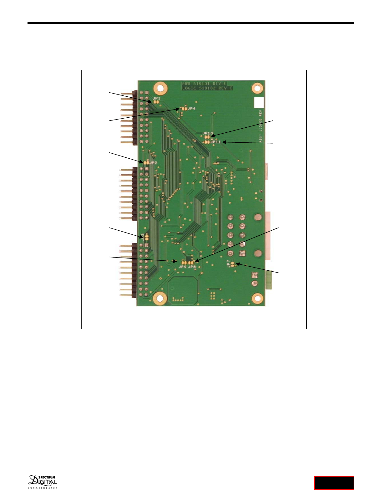
3.2 Jumpers
This section describes the jumpers on the AppBox D21 CPU Board. All jumpers are located on the bottom
side of the circuit board. All jumpers are surface mount jumpers. The figure below shows the location of each
jumper.
AppBox D21 CPU Board Jumper Positions
JP1
JP2
JP3
JP4 JP10
JP11
JP7
JP8
JP9
Table of contents


