EVOC MEC--5004 User manual

MEC5004
Fanless Embedded PC with Low Power
Consumption
Version:A1

Announcement
TheinformationinthismanualrepresentsnopromiseorguaranteebyEVOC.EVOC
reserves the right to make changes to the manual, without prior notice to customer.
EVOC will notbe held liable for any direct,indirect, intended or unintended losses
and/orhiddendangersduetoinstallationorimproperoperation.
EVOC is a registered trademark of EVOC Intelligent Technology Co., Ltd. All
trademarks,registeredtrademarks,andtradenamesusedinthisUser’sGuidearethe
propertyoftheirrespectiveowners.
EVOCIntelligentTechnologyCo.,Ltd.©2008,CopyrightReserved.Nopartofthis
manual may be reproduced in any form or by any means, electronic or mechanical,
withoutpermissioninwritingfromEVOC.
SafetyInstructions
1. Pleasereadtheuser'smanualcarefullybeforeusingtheproduct.
2. Before inserting, removing or reconfiguring motherboard or expansion card,
firstdisconnectthecomputerandperipheralsfrom theirpowersources;
3. Before removing boards or computer, first turn off all power resources and
disconnectthepowercordfrompowersource;
4. Forwholeset,wheninsertingorremovingboards,firstdisconnectthecomputer
andperipheralsfromtheirpowersources;
5. Before you connect or unplug any signal cable, make sure all power cords are
unpluggedinadvance;
6. Toavoidpoweron/offcomputerfrequently,waitatleast30secondsafterturning
offthecomputerbeforereturningonthecomputer.
7. Staticelectricitycanharmsystemboards.PerformserviceatanESDworkstation
andfollowproperESDproceduretoreducetheriskofdamagetocomponents;
8. If there's no ESD workstation, You can take the following steps to prevent
damagefromelectrostaticdischarge(ESD):
a) Weara groundedwriststrapagainstyour skinto eliminate staticon your
body;
b) Always touch the metal chassis or frame before you touch any
componentsinthechassis;
c) Keep partof yourbodyincontact withthemetalchassisto dissipatethe
staticchargewhilehandlingcomponents;
d) Avoidallunnecessarymovement;
e) Handlecomponentsandboardswithcare.Don’ttouchthecomponentsor
contacts on a board. Hold a boardby its edges or by its metal mounting
bracket;
f) Placethecomponentsonagrounded,staticfreesurface.Useaconductive
foampadifavailablebutnotthecomponentwrapper.
g) Donotletthecomponentsslideontheoperatingplatform.
9. Usecrossheadscrewdrivertooperate.Amagneticscrewdriverisrecommended
(magnettocollectscrews).Donot leaveanytoolsorscrewsinsidethechassis;
10. Assureabundantcoolingandstreamlineventilation.

Contents
Chapter1ProductIntroduction ................................................................................ 1
Overview ....................................................................................................... 1
FeaturesandSpecification .............................................................................. 1
MainPerformances......................................................................................... 2
RequirementsofTransportationandStorage.................................................... 4
Troubleshooting ............................................................................................. 4
Chapter2Installation .............................................................................................. 5
ProductOutline .............................................................................................. 5
ProductDimension......................................................................................... 5
ExternalI/OInterfacesOutline........................................................................ 6
AssemblyExplanation.................................................................................... 7
CriticalPieceInstallation................................................................................ 7
IntroductiononSpecialInterfaces ................................................................... 8
SerialPortsandDigitalIOInterface................................................................ 9
Chapter3BIOSIntroduction ................................................................................. 12
Chapter4InstallationofDrivers ............................................................................ 13
Appendix.............................................................................................................. 14
DigitalIOProgrammingGuide..................................................................... 14

Chapter 1ProductIntroduction
MEC5004 1
Chapter1ProductIntroduction
Overview
MEC5004 is a sort of fanless Core 2 Duo embedded PC with low power
consumption; the alalloy chassis has goodperformance on airproof, dustproof,
heatdispersionandantivibration;themotherboardadoptsIntelCore2DuoU7500or
L7500 processor with low power consumption; Intel GM965+ICH8ME chipsets
integratingGMAX3100graphicprocessingcouldsharedisplaymemory invastrange;
italsosupportsVGAandDVIindependentdualdisplay,whichcouldbewidelyused
inGPS,intelligenttransportation,digitalvideocontrollingsystemandsoon.
FeaturesandSpecification
CPU
IntelCoreDuoU7500/L7500.
Chipset
IntelGM965+ICH8ME.
SystemMemory
OneSODIMM slot,support 2GBDDR2533/667MHz memory.
NetworkFunction
One PCIE x1 RTL8111C Gigabit Ethernet chipset; one Intel 82566MC Gigabit
Ethernet chipset.

Chapter1ProductIntroduction
2 MEC5004
VideoFunction
Builtin Mobile Intel® Graphics Media Accelerator X3100; support LVDS output,
LVDSandCRTcoulddisplaysimultaneously;alsosupportTVoutput.
AudioFunction
OnboardastandardAC’97audioeffectchipset,provideexcellent soundeffect.
ExpansionBus
OnePCIEexpansionslot; onePCI expansionslot.
I/OFunction
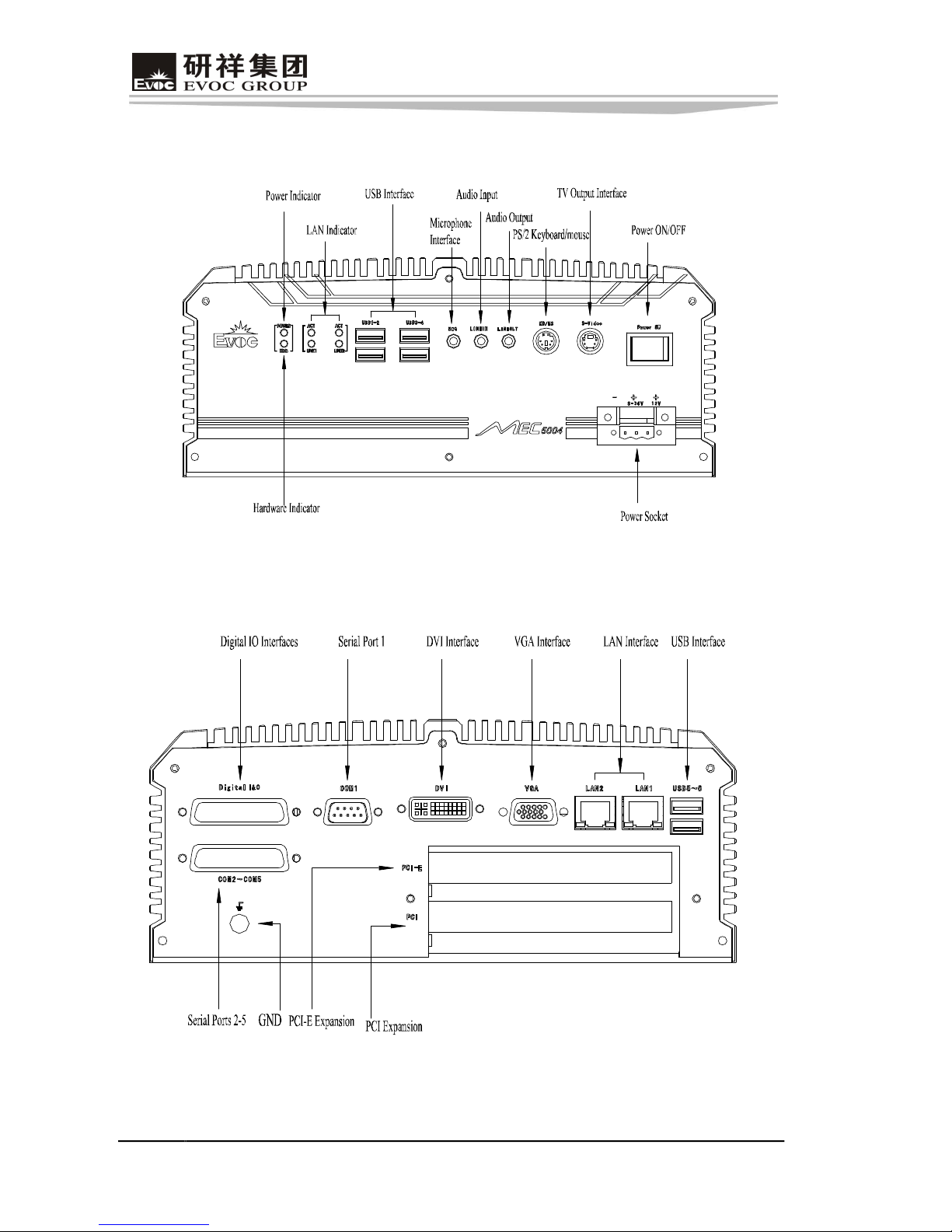
Ø Four USB interfaces on the front, one PS/2 keyboard/mouse interface, one
Svideointerfaceanda setofaudiointerfaces;
Ø TherearIOboardprovidestwoGigabitEthernetports,oneVGAinterface,one
DVIinterface,oneGPIOinterface,fiveCOMportsandtwoUSBinterfaces.
PowerSupplySelection
WidevoltageDC9V~36V/DC12V dualinput,redundancypowersupply.
MainPerformances
Environment/ WeightandDimensions
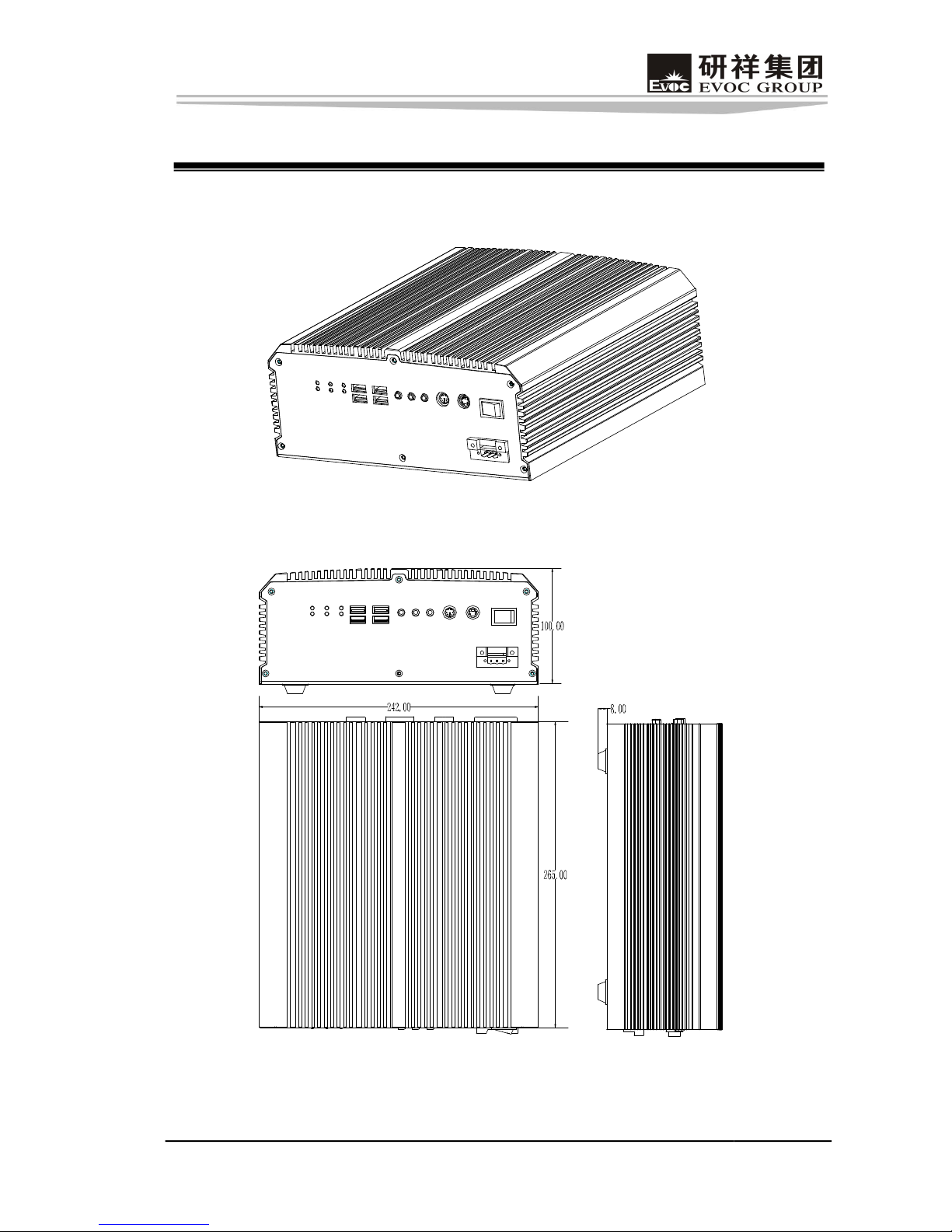
l Dimensions: 242.00mm(W) x 265.00 mm(D)x 100.00 mm(H)
l Weight: 4.5 Kg
l OperatingTemperature: 10°C~+55°C
l Relative Humidity: RH=93%(noncondensing);
l NonOperatingTemperature: 40°C~ +60°C

Chapter1ProductIntroduction
MEC5004 3
EMCCompliance
1. Limitof InterferenceofElectromagnetic Product
l LimitsofradiodisturbanceiscompliantwithGB 92541998, classA.
l Harmoniccurrent iscompliantwiththelimitsofGB/T17625.11998,classD.
2. AntiinterferenceCapacityofElectromagneticProduct
l ElectrostaticdischargeimmunitytestiscompliantwithGB/T17626.298,class3.
l Immunity test of radiation from radio frequency electromagnetic field is
compliantwithGB/T17626.398, class2.
l Immunity to conducted disturbances induced by radiofrequency fields is
compliantwithGB/T17626.698, class2.
l ElectricalFastTransientBurstImmunitytestiscompliantwithGB/T17626.498,
class2.
l Voltage dips, short interruption and voltage variations immunity tests are
compliantwithGB/T17626.1198.
l SurgetestiscompliantwithGB/T17626.599, class2.
Reliability
l MTBF 5000h≧ ;
l MTTR 0.5h≦ ;
Safety
Meet the requirements in 1.7 “marking and instruction” and 2.3, 2.9 “electric
structure” ofGB4943.

Chapter1ProductIntroduction
4 MEC5004
Mechanical Adaptability
l Antivibration:amplitude519Hz/1.2mm;acceleration19200Hz/1.2g;
l Antishock:acceleration15g,duration11ms.
RequirementsofTransportationandStorage
l Transportation:
Wellpackaged products suit for transportation by truck, ship, and plane. During
transportation, products should not be put in open cabin or carriage. When
transshipping en route,products should not be stored in the openwithoutprotection
from the atmospheric conditions. Products should not be transported together with
inflammable,explosiveandcorrosivesubstancesandarenotallowedtobeexposedto
rain,snowandliquidsubstancesandmechanicalforce.
l Storage:
Products should be stored in package box when it is not used. And warehouse
temperature should be 0°C~40°C, and relative humidity is 20%~85%. In the
warehouse, there should not be harmful gas, inflammable, explosive products, and
corrosive chemical products, and strong mechanical vibration, shock and strong
magneticfieldaffection.The packageboxshouldbeovergroundatleast10cmheight,
and50cm awayfromwall,thermalsource,andvent.
Troubleshooting
Please refer to Common Trouble Analysis and Treatment of Industrial Control
Computer foradetaileddescriptionofthetroubleshooting.
Chapter2 Installation
MEC5004 5
Chapter2Installation
ProductOutline
ProductDimension
Unit:mm
Chapter2 Installation
6 MEC5004
ExternalI/OInterfacesOutline
FrontPanel IOInterfaces
Rear PanelIOInterfaces

Chapter2 Installation
MEC5004 7
AssemblyExplanation
1. LeftPanel 2. I/OFrame 3. Rear Panel
4.Cover 5. Right Panel 6.FrontPanel
7.HardDisk 8. BottomCover 9. PCI TransferBoard
10. Carrier 11.HeatConductive AluminumPlate 12.Power
CriticalPieceInstallation
Whenassemblingthecoreboard,pleaseassembletheheatconductivealuminumplate,
thecoreboardandthecarriertogetherfirstly andtheninstallitintothemachinesoas
to ensure the core board is securely connected with the interfaces on board. PCI
transfer board can be inserted to the slot directly and fixed to the left panel with
screws.
Chapter2 Installation
8 MEC5004
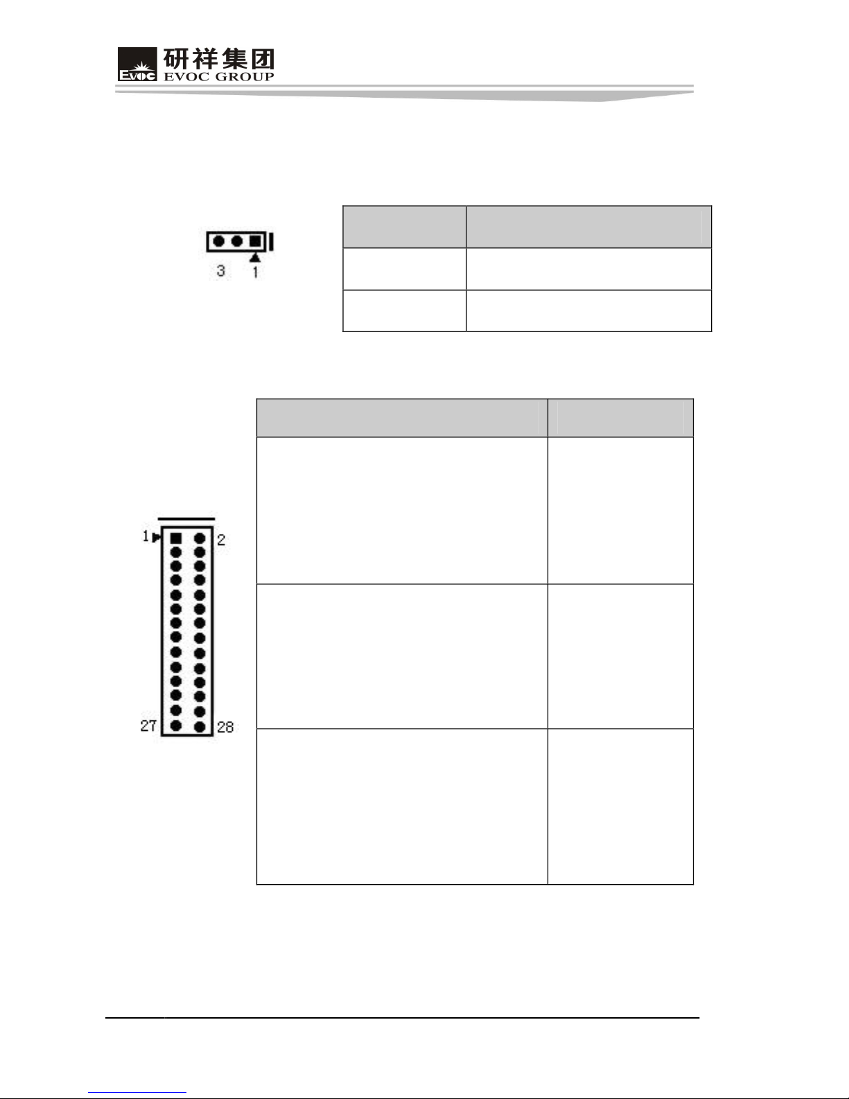
Introduction onSpecialInterfaces
Select differentinterfacemodes throughsetupthejumperontheboard.
1. Selectionforthe Compact Flash CardPower(JCF1)
Setup Function
[12] Short +3.3V
JCF1 [23] Short +5V (Default)
2. Selectionforthe COM1RS232/RS422/RS485 Mode(JPCOM1)
Setup Function
[12] Short [34] Short
[56] Short [78] Short
[910] Short [1112] Short
Otherpinsaredisconnected
RS232 Mode
[1314] Short [1516] Short
[1718] Shorted[1920] Shorted
[2122] Shorted[2324] Shorted
Otherpinsaredisconnected
RS422 Mode
JPCOM1
[1718] Shorted[1920] Shorted
[2122] Shorted[2324] Shorted
[2526]Shorted [2728] Shorted
Otherpinsaredisconnected
RS485 Mode

Chapter2 Installation
MEC5004 9
SerialPortsandDigitalIOInterface
Providefiveserialportsandtwosetsof8lanedigitalI/Ointerfaces;oneoftheserial
ports is a standard DB9 interface (COM1). Through jumper setup, users can
implement mode selection among RS232/RS422/RS485. In addition, the four
serial ports COM2, COM3, COM4 and COM5, switched from interface J1, could
connect with devices with standard RS232 interface, like mouse, modem, digital
cameraandsoon.
SignalName
Pin
RS232 RS422 RS485
1 DCD# TXD Data
2 RXD TXD+ Data+
3 TXD RXD+ X
4 DTR# RXD X
5 GND GND GND
6 DSR# X X
7 RTS# X X
8 CTS# X X
COM1
9 RI# X X
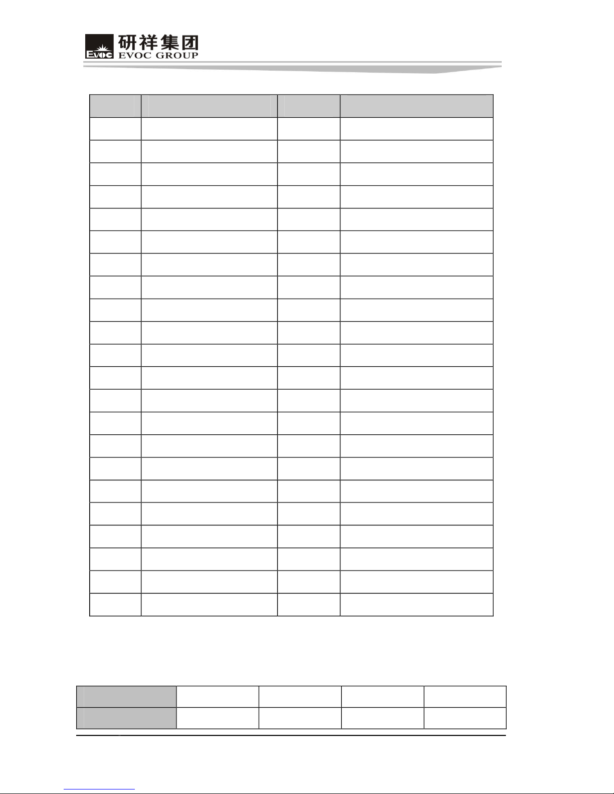
InterfaceDefinitionof COM2,COM3,COM4,COM5 and GPIO:
J1
Chapter2 Installation
10 MEC5004
Pin COM2, COM3 Signal Pin COM4, COM5 Signal
1 COM2_DCD 23 GND
2 COM2_RXD 24 COM4_DTR
3 COM2_TXD 25 COM4_DSR
4 GND 26 COM4_RTS
5 COM3_DCD 27 GND
6 COM3_RXD 28 COM5_DTR
7 COM3_TXD 29 COM5_DSR
8 GND 30 COM5_RTS
9 COM4_DCD 31 COM2_CTS
10 COM4_RXD 32 COM2_RI
11 COM4_TXD 33 GND
12 GND 34 GND
13 COM5_DCD 35 COM3_CTS
14 COM5_RXD 36 COM3_RI
15 COM5_TXD 37 GND
16 COM2_DTR 38 GND
17 COM2_DSR 39 COM4_CTS
18 COM2_RTS 40 COM4_RI
19 GND 41 GND
20 COM3_DTR 42 GND
21 COM3_DSR 43 COM5_CTS
22 COM3_RTS 44 COM5_RI
Note:Thecorresponding relationshipbetweenthefourserialports(COM2,
COM3,COM4,COM5)andexternalwiresilkscreenisshowedasfollows:
SerialPort COM2 COM3 COM4 COM5
Silkscreen D C B A

Chapter2 Installation
MEC5004 11
Pin GPIO SignalName Pin GPIO SignalName
1 INPUT0 23 OUTPUT7
2 INPUT1 24 GND
3 INPUT2 25 GND
4 INPUT3 26 GND
5 INPUT4 27 GND
6 INPUT5 28 GND
7 INPUT6 29 GND
8 INPUT7 30 GND
9 GND 31 VCC3.3
10 GND 32 VCC3.3
11 GND 33 GND
12 GND 34 GND
13 GND 35 GND
14 GND 36 GND
15 GND 37 GND
16 OUTPUT0 38 GND
17 OUTPUT1 39 GND
18 OUTPUT2 40 GND
19 OUTPUT3 41 GND
20 OUTPUT4 42 GND
21 OUTPUT5 43 GND
22 OUTPUT6 44 GND

Chapter3 BIOSIntroduction
12 MEC5004
Chapter3 BIOSIntroduction
FormoreinformationaboutBIOSsetup,pleaserefertoour AMIBIOSSetupGuide.

Chapter4InstallationofDrivers
MEC5004 13
Chapter4Installation ofDrivers
Regardingtheinstallationofthedriverprogramoftheproduct,pleaserefertotheCD
ofassociatedPC.

Appendix
14 MEC5004
Appendix
DigitalIOProgrammingGuide
#defineopen{outportb(INDEXP,0x87);outportb(INDEXP,0x87);}
intINDEXP=0x2e;
intDATAP=0x2f;
intHardwareID=0;
shortSetIndexData()
{
outportb(INDEXP,0x87);
outportb(INDEXP,0x87);
outportb(INDEXP,0x20);
HardwareID=inportb(DATAP);
If (HardwareID==0xff)
{
INDEXP=0x4e;
DATAP=0x4f;
}
return 0;
}
voidwrite(intreg,intdata)
{
outportb(INDEXP,reg);
outportb(DATAP,data);
}
intread(intreg)

Appendix
MEC5004 15
{
intvalue;
outportb(INDEXP,reg);
value=inportb(DATAP);
return(value);
}
intval;
int data[2];
SetIndexData();
open
val=read(0x2c);
val&=0xfe;
val|=0x02;
write(0x2c,val); //selectGPIO4asGPIO
write(0x07,0x09);
write(0x30,0x04);
write(0xf4,0x0f); //selectGP40~GP43in;GP44~GP47out;
write(0xf6,0x00);
write(0xf5,0x00);
sleep(1);
write(0xf5,0xf0);
Please visithttp://www.evoc.com formoreinformation.

声明
本手册包含的内容并不代表本公司的承诺,本公司保留对此手册更改的权
利,且不另行通知。对于任何因安装、使用不当而导致的直接、间接、有意或无
意的损坏及隐患概不负责。
EVOC 是研祥智能科技股份有限公司的注册商标。本手册所涉及到的其他商
标,其所有权为相应的产品厂家所拥有。
研祥智能科技股份有限公司©2008,版权所有,违者必究。未经许可,不得
以机械、电子或其它任何方式进行复制。
安全使用小常识
1. 产品使用前,务必仔细阅读产品说明书;
2. 为避免人体被电击或产品被损坏,在每次对板卡进行拔插、重新装配或配
置前,须先关闭交流电源或将交流电源线从电源插座中拔掉;
3. 在需对产品进行搬动时,务必先将交流电源线从电源插座中拔掉;
4. 当产品需增加/减少板卡时,务必先拔掉交流电源;
5. 当需连接或拔除任何信号线前,须确定所有的电源线事先已被拔掉;
6. 为避免频繁开关机对产品造成不必要的损伤,关机后,应至少等待 30 秒后
再开机;
7. 如果要进行升级或拆装等动作,须在静电放电工作台上完成所有操作,因
为有些精密器件对静电放电(ESD)很敏感;
8. 如果没有静电放电工作台,可通过以下方法降低 ESD 可能造成的危害:
a) 戴上一条防静电腕带并与相应产品的金属部分相连;
b) 在触摸产品部件前,先触摸相应产品机箱上的金属壳;
c) 当插拔部件时,身体最好与产品的金属机箱保持接触,以释放静电;
d) 避免不必要的走动;
e) 拿产品部件(尤其是板卡)时仅拿住边缘;
f) 将产品部件置于一个接地的无静电的操作平台上。如果可能的话,使
用一块导电泡沫垫(非部件的包装材料);
g) 不要让部件在操作平台上滑动。
9. 用十字螺丝刀进行操作,最好是强力螺丝刀(带磁性,避免螺丝遗留在机
箱内)。要注意的是,一定不要将工具或零件遗漏在机箱内;
10. 保证系统良好的散热与通风。

目 录
第一章 产品介绍..................................................................................................1
简介...............................................................................................................1
主要功能介绍................................................................................................1
主要性能指标................................................................................................2
运输与贮存要求 ............................................................................................3
常见故障处理................................................................................................4
第二章 安装说明..................................................................................................5
产品外观图....................................................................................................5
产品安装尺寸图 ............................................................................................5
外部 IO 接口图..............................................................................................6
装配说明........................................................................................................7
主要载板安装说明.........................................................................................7
特殊接口介绍................................................................................................8
串口与数字 IO 接口 ......................................................................................9
第三章 BIOS 功能简介.......................................................................................12
第四章 驱动程序安装说明 .................................................................................13
附录......................................................................................................................14
数字 IO 编程指引 ........................................................................................14
Table of contents
Other EVOC Industrial PC manuals

EVOC
EVOC LNB-1406 User manual

EVOC
EVOC NPC-8130 User manual

EVOC
EVOC PPC-1006 User manual

EVOC
EVOC IPC-8462 User manual

EVOC
EVOC ERC-1004A User manual

EVOC
EVOC P15 Series User manual

EVOC
EVOC MEC-4032 User manual

EVOC
EVOC EIS-2205 User manual

EVOC
EVOC P12 Series User manual

EVOC
EVOC MEC-5031-M Series User manual


