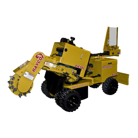
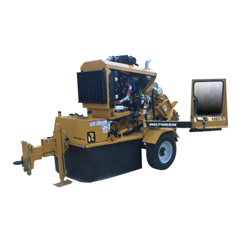
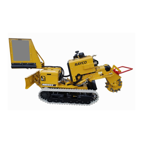
Rayco RG80 2019 User manual

RG80
PARTS MANUAL
RAYCO MANUFACTURING © 2019 ALL RIGHTS RESERVED
PRINTED IN USA
INDEX: PMRG80-19

RG80 Parts Manual
2
This manual is published by Rayco Manufacturing, Inc. for the
benefit of the users of Rayco products. Rayco Manufacturing,
Inc. has made every effort to ensure that this manual is
correct and up to date at the time of publication. However,
due to continuous improvements, Rayco Manufacturing, Inc.
reserves the right to make changes in the contents, at any
time, without notice or obligation.
Each machine shipped contains operation, maintenance
& parts manuals to familiarize the operator with the proper
operating, lubricating and maintenance instructions. This
helps to ensure the best possible performance and service
from the machine. Read and understand all instructions before
attempting to operate this machine. This manual should be
readily available for reference at all times. Additional copies
of this manual may be purchased from Rayco.
This Rayco machine was designed and manufactured by
Rayco Manufacturing, Inc., Wooster, Ohio. Due to continuous
improvements, Rayco reserves the right to make changes
in engineering, design and specifications, or discontinue
manufacture, at any time, without notice or obligation.
Always have a record of the model numbers and serial
numbers for your machine to specify when ordering parts.
Record your machine model and serial numbers on page 8
for your personal records.
Introduction
NOTICE:
Maintenance and Repairs should ONLY be performed by a trained
specialists or qualified personel.
Please contact Rayco Mfg for a listing of approved maintenance
facilities in your area.

RG80 Parts Manual
800.392.2686 3
Machine Description
Literature Information
The operators manual should be stored in the operator’s
compartment in the literature holder storage area. Rayco
provides a binder to hold the Operator Service Manual, Parts
Manual, Engine Manual along with other component manuals.
These manuals contain safety information, operation
instruction, transportation information, lubrication information
and maintenance information.
Some photographs or illustrations in the publication show
details of attachments that can be different from your machine.
Guards and covers might have been removed for illustrative
purposes. Continuing improvementmay have caused changes
to your machine which may not be included in this publication.
Continuing improvement and advancement of product
design might have caused changes to your machine which
are not included in this publication. Read, study and keep
this manual with the machine.
Whenever a question arises regarding your machine, of this
publication, please consult your Rayco dealer for the latest
available information.
Safety
The safety section lists basic safety precautions. In addition,
this section may include text and locations of warning signs
and labels used on the machine.
Read and understand the basic precautions listed in the
safety section before operating or performing lubrication,
maintenance and repair on this machine.
Parts
Parts are readilyfound through illustrations with accompanying
Rayco part numbers. The machine assembly is listed by basic
groups to enable ease of finding parts.
Please consult your local Rayco Dealer or local Engine
Manufacturer Dealer for obtaining engine parts and service
Operation
The operation section is a reference for the new operator
and a refresher for the experienced operator. This section
includes a discussion of gauges, switches, machine controls,
attachment controls, transportation and towing information.
Photographs and illustrations guide the operator through
correct procedures of checking, starting, operating and
stopping the machine.
Operating techniques outlined in this publication are basic.
Skill and techniques develop as the operator gains knowledge
of the machine and its capabilities.
Maintenance
The maintenance section is a guide to equipment care.
The Maintenance Interval Schedule lists the items to be
maintained at a specific service interval. The Maintenance
Interval Schedule lists the page number for the step-by-
step instructions required to accomplish the scheduled
maintenance procedure.
Maintenance Intervals
Use the service hour meter to determine servicing intervals.
Calendar intervals shown (daily, weekly, monthly, etc.) can be
used instead of service hour meter intervals if they provide
more convenient servicing schedules and approximate the
indicated service hour meter reading. Recommended service
should always be performed at the interval that occurs first.
Under extremely severe, dusty or wet operating conditions,
more frequent lubrication than is specified in the maintenance
intervals chart might be necessary.
Perform service on items at multiples of the original
requirement. For example, at every 100 service hours, also
service those items listed under every 50 service hours and
every 10 service hours or daily.
Certified Engine Maintenance
Proper maintenance and repair is essential to keep the engine
and machine systems operating correctly. As the heavy duty
off-road engine owner, you are responsible for the required
maintenance listed in the Engine Owner Manual & Machine
Operator, Maintenance & Service Manual.
Attach a “Do Not Operate” warning tag or a similar warning
tag to the start switch or to the controls before you service
the equipment or before you repair the equipment.
Know the width of your equipment in order to maintain proper
clearance with you operate the equipment near fences or
near boundary obstacles.
Be aware of high voltage power lines and power cables
that are buried. If the machine comes in contact with these
hazards, serious injury or death may occur from electrocution.
Wear a hard hat, protective glasses, and other protective
equipment, as required.
Do not wear loose clothing or jewelry that can snag on
controls or on other parts of the equipment.
Make sure that all protective guards and all covers are secured
in place on the equipment.
Keep the equipment free from foreign material. Remove
debris, oil, tools, andother items from the deck,from walkways,
and from steps.

RG80 Parts Manual
4
Secure all loose items such as lunch boxes, tools, and other
items that are not a part of the equipment.
Know theappropriate work site hand signalsand the personnel
that are authorized to give the hand signals. Accept hand
signals from one person only.
Do not smoke when you service an air conditioner. Also, do
not smoke if refrigerant gasmay be present. Inhaling the fumes
that are released from a flame that contact air conditioner
refrigerant can cause bodily harm or death. Inhaling gas
from air conditioner refrigerant through a lighted cigarette
can cause bodily harm or death.
Never put maintenance fluids into glass containers. Drain
all liquids into a suitable container.
Obey all local regulations for the disposal of liquids.
Use all cleaning solutions with care. Report all necessary
repairs.
Do not allow unauthorized personnel on the equipment.
Unless you are instructed otherwise, perform maintenance
with the equipment in the servicing position. Refer to
Operation and Maintenance Manual for the procedure for
placing the equipment in the servicing position.
When you perform maintenance above ground level, use
appropriate devices such as ladders or man lift machines.
If equipped, use the machine anchorage points and use
approved fall arrest harnesses and lanyards.
Machine Description
The RG80 Series stump cutter is designed for your maximum
benefit for every dollar spent. The machine is constructed for
durability and easy maneuvering, for those hard to reach tree
stumps and roots. Its 23” diameter cutting wheel with 24
Rayco Supertooth® is powerfully driven through a variable
displacement axial piston pump and a synchronous belt with a
85 hp Ford 2.5L, EPA/CARB compliant, Vertical 4-cycle, liquid
cooled gasoline engine at its source. Cutting boom motion
and the self-propel drive are entirely hydraulic, with 2 speeds.
The machine chassis features rectangular steel tubing and
steel guard construction, mounted on extra gripping deep
tread tires. The operator benefits from a remote operator
station which allows optimal views of the cutting action, all
while being guarded by heavy rubber curtains.
The RG80 Series stump cutter has the ability to pass through
a 47” gate under its own power. Other special features of
the RG series include a slewing ring that is used to pivot the
cutter boom, replaceable composite bushings on all cylinder
ends, 10.2 gallon fuel tank, steel belt guards, and an easy
access ignition switch on the machine.
Other options that have become available on the RG series
are dual removable travel wheels for increased stability and
travel traction, Command Cut®, and a blade for pushing
chips back into place.
Forfurther design informationsee the“Specifications”section
Machine Description
CALIFORNIA PROPOSITION 65
WARNING THIS MACHINE AND ITS
CONSTIUENTS ARE KNOWN IN THE STATE
OF CALIFORNIA TO CAUSE CANCER AND
REPRODUCTIVE HARM.
VISIT WWW.P65WARNI NGS.CA.GOV

RG80 Parts Manual
800.392.2686 5
Machine Specs
General
Weight: 3230 Lbs Maximum
Length: 142” Maximum
Height: 55” Maximum (Hydraulic motor hose
holder), 82” (Cutter wheel hoses)
Width: 51” Maximum (Blade extensions out), 47”
Minimum (Blade extensions in)
Ground Clearance: 7.5” Minimum
Chassis Design: Electrically welded formed,
structural Steel 1/4”, 3/8”, 5/8”, 3/4”
Self-Propel Means: Hydraulic/Planetary Wheel
Motor
Swing Pivot Bearings: 1-3/4” Greased Steel
Bushings
Cylinder Pivot Points: 1”, 1-1/4”, Greased Steel
Bushings
Warning Lights: Display includes warning lights
and error messages to easily troubleshoot warn-
ings.
Ground Pressure: 5.5PSI (ISO 16754)
Engine
Model: Ford 2.5L, Vertical 4-cycle, spark ignited,
liquid cooled, gasoline
Number of cylinders: 4
Displacement: 153 cu. in
Maximum no load RPM: 3200
Gross HP at maximum no load RPM: 85 HP
Maximum rated torque: 140ft lbs @ 2400 RPM
Cooling medium: liquid cooled
Air Cleaner: Dry type with Pre-Cleaner
Oil Filter: Spin-on type
Fuel Tank Capacity: 10.2 Gallons
Electrical System: 14 volts/ 65-110 AMP Alterna-
tor, 12 volt electrical starter
Engine: to be operable on (up to) a 30° slope with
the cutter wheel in the full up or down position
Engine: must remain level with machine frame and
not tilt upward or downward while in operation.
Also, engine must not move left or right while in
operation.
Hydraulic System - Cutter
Cutter Pump: Variable displacement axial piston
Cutter Motor: Fixed displacement axial piston
Cutter Pump Displacement: 45cc Maximum
Command Cut: Swing speed control and horse-
power optimizer
Filter: Easy access suction filter and charge pres-
sure filter
System Pressure Relief: 5000 PSI
Lift & swing cylinders: Lift- 3” bore x 8” stroke,
1-1/4” rod; Swing- 2 ½” bore x 7-3/16” stroke,
1-1/8” rod
Oil Type: Tellus T46
Hydraulic Tank Capacity: 8.8 Gallons
Hydraulic Wheel Drive System
Wheel Drive Pump: Gear
Wheel Drive Motors: Axial 2-speed piston motor
Control Valve: Manifold Type Electronic Control
System Pressure Relief: 3200PSI
Cutting Wheel
Wheel Diameter: 23”
Wheel Thickness: 1.5”
Cutting Wheel Bearings: 2-3/16” diameter double
row spherical roller
Cutter Wheel RPM: 850 RPM @ 3200 RPM
Engine Speed
Drive Belt: Mitsuboshi GigaTorque® GX
Cutting Teeth: RAYCO Super tooth™ forged, one
piece, with tungsten carbide tips.
Cutter Teeth Quantity: 24 Maximum
Belt Guard: Steel, one piece
Chip Retaining Curtains: two ply nylon neoprene,
three ply belting grade 2
Cutter Wheel: Must come to a stop in less than
three seconds without shutting off engine
Cutter Wheel Engagement: Hydrostatic pump. No
clutch necessary
Cutting Range (without repositioning)
Below Ground Level: 21”
Above Ground Level: 20”
True Cutting Width (NOT ARC): 57”
Forward - Backward: Self-propelled unlimited
Options
TR100L Trailer

RG80 Parts Manual
6
Serial Number Location & Information
Serial Numbers Location
Whenever communicating with Rayco or your Rayco dealer,
have your machine serial number handy, as it can help
pinpoint most exactly what information is needed in caring
for your machine.
Breakdown of the serial number
For Example:RG80 001 01 19
RG80 - Type of Rayco equipment you have
001 - Three digit for the number of produced
01 - Two digit month, 01 = Jan., 02 = Feb., etc...
18- Two digit year, 18 = 2018, 19 = 2019, etc
It is attached to the machine at the location shown. For
ready reference, record it in the boxes provided on page 8.
For reference on communication regarding the engine,
record its model and serial numbers also in the boxes
provided on page 8 of this manual. See the Engine
Operator Manual for assistance in locating the numbers
on the engine.
RG80
RG80 0010119
38458
3230/1465 (kg)
2019
85HP (63kw)
STUMP CUTTER
RG80 =Type of Rayco Equipment
001= The three digit number of produced
Production Date; 01=2 digit month; 19= 2 digit year

RG80 Parts Manual
800.392.2686 7
Serial Number Location & Information
Identification Numbers
Model Number Serial Number
Machine
Engine
Implement
Implement
Dealer Information
Name
Address
Dealer Contact Phone Number Hours
Sales
Parts
Service
Serial number is located as shown.
Use the below table to record identification numbers and dealer information.

RG80 Parts Manual
8
38347 Frame Assembly Rev G
2
3
511
8
56 21 38 28
55 26 17
9
40
1 18
6
7222834
32
51 52
58
44
4
61
62
48 36 24
SECTION A-A
722836 QTY. 8 EACH SIDE
804590 QTY. 8 EACH SIDE

RG80 Parts Manual
800.392.2686 9
38347 Frame Assembly Rev G
40
40
57
53 37 25
48 24 36
4215 63
CUT TO 20.5"
14
53372524
32
63
CUT TO 15.5"
202928
30
ITEMS NOT SHOWN (3) 764712
TEE-MINICHECK -6 ORFS
13
35
39 41 19 27 23
45
60
800857 TRIM SEAL
AROUND PERIMETER
OF RADIATOR OPENING

RG80 Parts Manual
10
ITEM QTY. PART # DESCRIPTION
1 1 11543 FILTER ASM, REWORK
2 1 34588 BLADE, ASSEMBLY
3 1 38241 PROPEL GROUP ASM
4 1 38267 FUEL TANK GROUP ASM
5 1 38274 HYD TANK GROUP ASM
6 1 38342 FRAME WELDMENT RG80A
7 1 38363 HOOD SPINE WELDMENT
8 1 38373 INSTRUMENT PANEL ASM
9 1 38381 ROD, HOOD PROP
10 138709 HARNESS-MAIN/VALVE RELAY
AND FUSE
11 1 38803 SUPPORT, HOOD HOSE ASM
RG80A
12 1 38804 CLAMP, INLINE FILTER
13 1 39945 TAG, DANGER HOT WARNING
14 1 40188 TRAY, BATTERY
15 1 40189 PAD, BATTERY 6X10
16 1 722105 BOLT HEX 1/4-20 X 1 1/4”
17 2722107 BOLT HEX 1/4-20 X 1 3/4
18 4 722114 BOLT WHIZ 3/8-16 X 3/4 GR8.2 ZP
19 2 722205 BOLT HEX 5/16-18 X 1 GR8
20 1 722303 BOLT-HEX 3/8-16 X 1
21 3 722340 BOLT HEX 3/8-16X5-1/2GR8
22 4 722722 BOLT BHS 3/8-16 X 1
23 2 724201 NUT HEX 5/16”-18 GR8
24 4 724508 NUT LOCK 1/4-20 NYLOCK
25 2 726101 WASHER FLAT 1/4 USS
26 3 726102 WASHER-LOCK, 1/4”
27 2 726202 WASHER LOCK 5/16” PLATED
28 11 726300 WASHER FLAT 3/8 SAE
29 1 726302 WASHER-LOCK 3/8
30 2730080 GREASE ZERK 1/8 PTF STR
31 1 730100 GROMMET-RUBBER 9/16” ID
32 2 730131 HOSE-LUBRICATION 20”
33 2 750050 NUT LOCK 5/16-18 NYLON
34 4 750061 NUT-WHIZ 3/8-16 SERR FLANGE L/N
GR8 ZN
35 4 750463 RIVET-3/16 X 3/8 STLMAND
36 2 750955 BOLT HEX 1/4-20 X 2 GR8
37 2760237 BOLT-HHCS 1/4-20X3.25 GR8
38 3 760261 NUT-HNNL 3/8-16 INS
39 1 761900 GROMMET-RUBBER 11/16” ID
40 15 762499 BUMPER-HOOD
41 2 763757 WASHER FLAT 5/16 HARDENED
42 1 800622 BATTERY-34/78-72
43 1 802967 FILTER- FUEL GM 3.0L/ 4.3L
44 1802986 VALVE-SHUTTLE -04 ORB
45 1 802998 TUBE-MANUAL 2” DIA X 12.5”
LONG
46 2 803428 CLAMP, 2” VINYL
47 1 803432 PUMP-FUEL
48 1 803433 SENSOR- TEMP AND PRESSURE
49 2803434 FITTING- -6 STOR 5/16
50 2 803435 FITTING- -3 STOR 5/16
51 1 805187 ANTENNA LXM RECEIVER
52 1 805188 CONNECTOR, BULKHEAD LXM
RECEIVER
53 2 805773 VALVE-FLOW DIVIDER 6.0GPM
32 3 805787 FILTER-HYD INLINE 10 MICRON SAE
6
55 1 805841 VALVE-FLOW CONTROL 4.0GPM
56 1805867 VALVE-COMBO BLOCK RG80A
57 1806036 CABLE-RECEIVER RP-SMA TYPE N
COAX 3FT
58 1806039 PLUG-DUST M12 X 1 MALE
59 1FUEL
HOSE
ASSEM-
B LY
FUEL LINE LAYOUT
60 65” 800857 SEAL-RUBBER RIBBED 3/8” X 1/2”
61 4 722103 BOLT HEX 1/4-20 X 3/4 GR8
62 4 750768 NUT-WHIZ 1/4-20 SERR FLANGE
L/N
GR8 ZN
63 36” 761641 TRIM-EDGE TRIM-LOK 1/4”
38347 Frame Assembly Rev G

RG80 Parts Manual
800.392.2686 11
11543 Filter Assembly Rev A
*
*
*
1
NOTE:
1. WIRE CONNECTOR AS FOLLOWS:
WHITE WIRE = POSITION "B"
RED WIRE = POSITION "A"
BLACK WIRE = POSITION "C"
OIL FILTER 762462
ITEM QTY. PART # DESCRIPTION
1 1 803264 FILTER-ASM PRESS, 3 PORT, W/METRIPAK SWITCH

RG80 Parts Manual
12
34588 Blade Assembly
1
2 5
5 2
1
3
3
3
3
910 13
25
67
18
18
17
16
11
14
15
8
19
18
12
20 13 10
ITEM QTY. PART # DESCRIPTION
1 4 765285 NUT-HNML 1”-14
2 8 750057 NUT-WHIZ 1/2-13 SERR FLANGE L/N
GR8 ZN
3 12 4900-38 WASHER 12 GA.X1.015X2.5
4 2 726907 WASHER FLAT 1-14GA
5 8 722504 BOLT HEX 1/2-13 x 1 1/2
6 4 722539 BOLT CARR 1/2”-13 X 1-1/2
7 4 724503 NUT-HNML 1/2-13 PREV TORQ GR8
8 4 27048 PIN WELDMENT
9 1 24237 CYLINDER,WELDMENT 10”
10 3 728004 PIN-COTTER 3/16 X 1-1/2
11 1 28306 ARM, LIFT WELDMENT
12 3 28303 ARM, BLADE
13 3 726906 WASHER FLAT - 1” 10 GA.
14 2 800972 PIN-CLEVIS 3/4 X 1 3/4 LG.
15 8 765313 BUSHING-COMP 1.25 X 1 X 1.25
16 1 34589 BRACKET, BLADE WELDMENT
17 134590 BLADE, WELDMENT RG45T
18 2 34594 BLADE, FOLDING WELDMENT
19 2 728038 HAIRPIN COTTER
20 1 38166 PIN,CLEVIS

RG80 Parts Manual
800.392.2686 13
ITEM QTY. PART # DESCRIPTION
1 1 38242 REAR STEERING AXLE ASM
2 2 38243 LEFT WHEEL ASM
3 2 38244 RIGHT WHEEL ASM
4 1 38245 DUAL WHEEL GROUP ASM
5 52 722836 BOLT MSHCS 10 X1.5 X 20
6 2 803811 DRIVE-FINAL
38241 Propel Assembly
3
6
12
3
2
4
56
MOUNT DRIVE TO WHEEL AND
FRAME USING 722836 BOLTS
NOTE: USE BLUE LOCTITE ON DRIVE BOLTS
AND TORQUE TO 55 LB-FT

RG80 Parts Manual
14
Steering Axle 38424 Rev A
11
9
11
9
9
5 13 10
2
1
12
NOTE: USE BLUE LOCTITE AND
TORQUE DRIVE BOLTS 804590 TO 55LBS-FT
3
3
14
15
4
4
61487
USE RED LOCTITE
6X
34
44
33
11
11
1

RG80 Parts Manual
800.392.2686 15
ITEM QTY. PART DESCRIPTION
1 1 38246 REAR STEER AXLE WELD-
MENT
2 1 38250 TIE-ROD ASM
3 2 38252 STEER AXLE SPINDLE
WELDMENT
4 2 38256 LOWER SPINDLE JOINT
WELDMENT
5 1 722201 BOLT HEX 5/16-18 X 2
GR8
6 6 722506 BOLT HEX 1/2 - 13 X 2
GR8
7 6 724501 NUT HEX 1/2-13 GR8
8 6 726502 WASHER LOCK 1/2
9 4 730011 ZERK-GREASE 1/4-28 STR
10 1 750050 NUT LOCK 5/16-18 NYLON
11 2 803811 DRIVE-FINAL RG45T
12 16 804590 BOLT MSHCS 10 X1.5
X 25
13 1 20405 PIN PIVOT STEER AXLE
14 2 760872 BEARING-GARMAX
1.25X1.00
15 1 12002 STEER CYINDER ASSY

RG80 Parts Manual
16
38267 Fuel Tank Assembly
ITEM QTY. PART # DESCRIPTION
1 1 38268 FUEL TANK WELDMENT
2 1 805835 SENDER-FUEL 16” TANK
3 1 801682 CAP-FUEL FULL TURN EPA
4 2 750057 NUT-WHIZ 1/2-13 SERR FLANGE L/N
GR8 ZN
5 2 761617 BOLT WHIZ 1/2 -13 X 1 1/4” GR8.2 ZP
6 5 764408 SCREW-#10-32 X 3/4” SLOTTED
PAN HEAD
7 5 760578 WASHER-SEALING #10
8 1 38840 KIT, FUEL TANK FOAM
9 2 38841 TANK BRACKET SPACER
10 1 724508 NUT LOCK 1/4-20 NYLOCK
11 1 804857 FIT-PLUG-6MOR
A
3
1
5 1 4
8
9
10
DETAIL A
SCALE 2 : 5
2
6 7 2
11

RG80 Parts Manual
800.392.2686 17
38274 Hydraulic Assembly Rev B
8
91
2
6
12
10
7
CHECK VALVE PLACED
ON INSIDE OF TANK
53
5 3
8
4
2
12
11
NOTE: SOME ITEMS HIDDEN FOR CLARITY

RG80 Parts Manual
18
38274 Hydraulic Assembly Rev B
HOC RETURN
HOC BYPASS
6803-12-12-12
REAR DRIVES
CASE DRAIN
FF6804-06-06-06
VALVE BANK RETURN &
CHARGE FILTER BYPASS
FF6804-12-12-12
FRONT DRIVES CASE
DRAIN & VALVE BANK
VENT
FF6804-06-06-06
TEMP SENSOR
LEVEL SENSOR
GEAR PUMP SUCTION 4CC
FOR CYLINDER FUNCTIONS
CUTTER PUMP SUCTION
GEAR PUMP SUCTION 6CC
FOR PROPEL
ITEM QTY. PART # DESCRIPTION
1 1 2743 9 SENSOR, HYD OIL LEVEL W/PLUG
2 1 38275 HYD TANK WELDMENT
3 2 750057 NUT-WHIZ 1/2-13 SERR FLANGE L/N
GR8 ZN
4 1 761051 MAGNET-HYD. RES.
5 2 761617 BOLT WHIZ 1/2 -13 X 1 1/4” GR8.2
ZP
6 1 800874 COVER-CLEAN-OUT TANK 10”
7 1 801012 VALVE-CHECK 25 PSI
8 1 802707 BREATHER- FILLER RESERVIOR
NYLON
9 1 805819 SWITCH-OIL TEMP 200° SAE #8
10 238841 TANK BRACKET SPACER
11 1 804857 FIT-PLUG-6MOR
12 1 806698 GAUGE-FUEL 4.5”

RG80 Parts Manual
800.392.2686 19
38286 Fuel System Assembly
NOTE: 803432 FUEL PUMP & 802967 FUEL FILTER
COME WITH THE 805820 ENGINE
2
2
6
6
6
2
2
10 5 1 8
93138
1211
1211
5
FUEL PUMP PROVIDED
WITH THE ENGINE
NOTE: ITEMS HIDDEN FOR CLARITY

RG80 Parts Manual
20
38286 Fuel System Assembly
9
8
8
10
8
8
8
10
10
8
810 8 10
8
10
10
9
ITEM QTY. PART # DESCRIPTION
1 1 38287 BRACKET, FUEL PUMP/FILTER
2 1 722104 BOLT HEX 1/4-20 X 1 GR8
3 2 722114 BOLT WHIZ 3/8-16 X 3/4 GR8.2 ZP
4 2 722724 BOLT HEX 1/4-20 X 2 1/4
5 3 724508 NUT LOCK 1/4-20 NYLOCK
678” 730043-2HOSE-FUEL LINE 5/16 30R7
7 2 750061 NUT-WHIZ 3/8-16 SERR FLANGE L/N
GR8 ZN
8 8 802628 QUICK CONNECT- FUEL 5/16 STR.
9 2 802629 QUICK CONNECT- FUEL 5/16 90
DEG
10 10 802849 CLAMP- STEPLESS EAR .52-.618 I.D.
11 2 803428 CLAMP, 2” VINYL
12 1 803433 SENSOR- TEMP AND PRESSURE
13 2 803434 FITTING- -6 STOR 5/16
14 2 803435 FITTING- -3 STOR 5/16
15 1
FUEL
SENDER
MOUNT
PLATE, MOUNT FLOW CONTROL
Table of contents
Other Rayco Cutter manuals