Speech Technology Center ANF II User manual

ANF II
Portable device for sound cleaning and
speech signals recording
STC-H474
Operating manual

Thank you for choosing the product of our company.
Before starting work with ANF II thoroughly read this Operating Manual. If there are some questions concerning the use of
the product, please contact the Speech Technology Center technical support service:
E-mail
support@speechpro.com
Telephone
+7 (812) 325-8848, ext. 2
Fax
+7 (812) 327-9297
Internet
http://www.speechpro.com/
We welcome your feedback, questions and concerns regarding ANF II.
If you have any questions concerning the use of this product, please contact Speech Technology Center’s technical support
service or your regional dealer.
The manufacturer retains the right to make amendments to this manual in connection with improvements made to ANF II
design without special notification.
Any such amendments will be published in a new edition of the Gnome manual and on the company’s website:
http://www.speechpro.com.
No part of this document can be copied or reproduced in any manner without the written permission of the Speech Technology Center.

CONTENTS
INTRODUCTION....................................................................................................................................................................................3
General provisions........................................................................................................................................................................................3
Operation instructions ................................................................................................................................................................................3
Typography conventions ...........................................................................................................................................................................3
Copyrights ......................................................................................................................................................................................................4
Warranty..........................................................................................................................................................................................................4
1 DEVICE MAIN FEATURES.................................................................................................................................................................5
1.1 Purpose .....................................................................................................................................................................................................5
1.2 About the product.................................................................................................................................................................................5
1.3 Functions..................................................................................................................................................................................................5
1.4 Settings of recording and playback channels................................................................................................................................6
1.5 Engineering data....................................................................................................................................................................................6
1.6 Power supply characteristics ..............................................................................................................................................................6
1.7 Software requirements.........................................................................................................................................................................6
2 DESIGN PHILOSOPHY......................................................................................................................................................................7
2.1 Device view..............................................................................................................................................................................................7
2.2 Device front panel .................................................................................................................................................................................8
2.3 Device back panel..................................................................................................................................................................................9
3 GETTING STARTED......................................................................................................................................................................... 10
3.1 Power supply.........................................................................................................................................................................................10
3.1.1 Inserting batteries................................................................................................................................................................................................ 10
3.1.2 Connecting the device to the external power supply .......................................................................................................................... 10
3.2 Memory card .........................................................................................................................................................................................11
3.2.1 Suitable memory cards ..................................................................................................................................................................................... 11
3.2.2 Removing write protection.............................................................................................................................................................................. 11
3.2.3 Inserting memory card...................................................................................................................................................................................... 11
3.3 Connecting headphones...................................................................................................................................................................12
3.4 Connecting to digital inputs and outputs ....................................................................................................................................12
3.5 Connecting to line outputs...............................................................................................................................................................12
3.6 Connecting to line inputs..................................................................................................................................................................12
3.7 Connecting to telephone line..........................................................................................................................................................12
3.8 Connecting to local network ............................................................................................................................................................13
3.9 Connecting to USB-port.....................................................................................................................................................................13
4 CONTROLS AND INDICATORS ................................................................................................................................................... 14
4.1 Controls...................................................................................................................................................................................................14
4.1.1 Power switch.......................................................................................................................................................................................................... 14
4.1.2 Navigation buttons ............................................................................................................................................................................................ 14
4.1.3 MENU button......................................................................................................................................................................................................... 14
4.1.4 RECORD button.................................................................................................................................................................................................... 14
4.1.5 MONITOR button................................................................................................................................................................................................. 14
4.1.6 Volume control..................................................................................................................................................................................................... 14
4.1.7 Controls of the left and right channels....................................................................................................................................................... 14
4.2 Indicators................................................................................................................................................................................................14
4.2.1 LCD............................................................................................................................................................................................................................. 14
4.2.2 Indicators of the recording level.................................................................................................................................................................... 15
5 MULTILEVEL MENU ....................................................................................................................................................................... 16
5.1 Multilevel menu structure .................................................................................................................................................................16
5.2 Navigation order in the multilevel menu......................................................................................................................................17
5.3 SD-card menu .......................................................................................................................................................................................18
5.4 Settings menu.......................................................................................................................................................................................19
5.4.1 Audio settings........................................................................................................................................................................................................ 19
5.4.2 Voice activation.................................................................................................................................................................................................... 22

CONTETS
5.4.3 Recorder timer menu ......................................................................................................................................................................................... 24
5.4.4 Overflow protection menu.............................................................................................................................................................................. 26
5.4.5 Security menu ....................................................................................................................................................................................................... 27
5.4.6 Date and time menu.......................................................................................................................................................................................... 28
5.4.7 Network settings .................................................................................................................................................................................................. 28
5.4.8 Other settings menu........................................................................................................................................................................................... 31
5.5 Utilities menu ........................................................................................................................................................................................33
5.6 Filters .......................................................................................................................................................................................................36
5.6.1 Broadband noise filter ....................................................................................................................................................................................... 36
5.6.2 Harmonic reject filter.......................................................................................................................................................................................... 38
5.6.3 Equalizer.................................................................................................................................................................................................................. 38
5.6.4 De-clicker................................................................................................................................................................................................................. 40
5.6.5 Speech level enhancer ....................................................................................................................................................................................... 41
5.6.6 Reference noise filter........................................................................................................................................................................................... 41
5.6.7 V changer ................................................................................................................................................................................................................ 43
5.6.8 Presets....................................................................................................................................................................................................................... 44
5.7 Lines selection menu..........................................................................................................................................................................45
6 OPERATION ..................................................................................................................................................................................... 47
6.1 Turning the device on ........................................................................................................................................................................47
6.2 Device general settings......................................................................................................................................................................47
6.3 Sound recording ..................................................................................................................................................................................48
6.3.1 Quick recording.................................................................................................................................................................................................... 48
6.3.2 Selecting sound source and recording settings...................................................................................................................................... 48
6.3.3 Recording in the manual mode .................................................................................................................................................................... 48
6.3.4 Recording in the Voice activation mode ................................................................................................................................................... 49
6.3.5 Recording by timer.............................................................................................................................................................................................. 49
6.3.6 Recording process indication......................................................................................................................................................................... 49
6.4 Playback of recorded audio files ......................................................................................................................................................50
6.4.1 Playback by device .............................................................................................................................................................................................. 50
6.4.2 Playback by PC...................................................................................................................................................................................................... 50
6.5 Deleting audio records.......................................................................................................................................................................50
6.6 Shutting down the device.................................................................................................................................................................50
7 DEVICE CONTROLLING VIA PC................................................................................................................................................... 51
7.1 Software requirements.......................................................................................................................................................................51
7.2 Connecting device to PC ...................................................................................................................................................................51
7.2.1 Connection via USB ............................................................................................................................................................................................ 51
7.2.2 Connection through local network............................................................................................................................................................. 51
7.3 Launching the application ................................................................................................................................................................51
7.4 Application main window tabs........................................................................................................................................................52
7.5 SD-card tab ............................................................................................................................................................................................52
7.5.1 Cleaning recycle bin ........................................................................................................................................................................................... 54
7.5.2 Formatting SD-card ........................................................................................................................................................................................... 54
7.6 Information tab.....................................................................................................................................................................................55
7.7 Monitor tab............................................................................................................................................................................................55
7.8 Filters tab ................................................................................................................................................................................................55
7.8.1 Broadband noise filter ....................................................................................................................................................................................... 56
7.8.2 Tone interference filter....................................................................................................................................................................................... 56
7.8.3 Equalizer.................................................................................................................................................................................................................. 57
7.8.4 De-clicker................................................................................................................................................................................................................. 57
7.8.5 Speech level enhancer....................................................................................................................................................................................... 57
7.8.6 Stereo filter.............................................................................................................................................................................................................. 58
7.8.7 V-changer ............................................................................................................................................................................................................... 58
7.8.8 Presets....................................................................................................................................................................................................................... 58
7.9 Settings tab............................................................................................................................................................................................59
7.9.1 Audio settings........................................................................................................................................................................................................ 59
7.9.2 Lines selection ....................................................................................................................................................................................................... 60
7.9.3 Voice activation.................................................................................................................................................................................................... 61

CONTETS
7.9.4 Recorder timer....................................................................................................................................................................................................... 62
7.9.5 Overflow protection............................................................................................................................................................................................ 63
7.9.6 Security..................................................................................................................................................................................................................... 63
7.9.7 Date and time ....................................................................................................................................................................................................... 64
7.9.8 Network settings .................................................................................................................................................................................................. 64
7.9.9 Other settings ........................................................................................................................................................................................................ 65
7.9.10 Default settings.................................................................................................................................................................................................. 65
7.10 Journals tab .........................................................................................................................................................................................66
7.11 Firmware tab.......................................................................................................................................................................................66
7.12 Disconnecting device from PC ......................................................................................................................................................67
APPENDIX A........................................................................................................................................................................................ 68
BROWSER SETTINGS FOR PROGRAM QUICK LAUNCH .....................................................................................................................68
A.1 Home page using...............................................................................................................................................................................68
A.2 Bookmarks usage................................................................................................................................................................................69
A.3 Usage of the shortcut on the desktop..........................................................................................................................................69
APPENDIX B ........................................................................................................................................................................................ 70
CERTIFICATE ADJUSTMENT IN INTERNET EXPLORER ........................................................................................................................70
APPENDIX C........................................................................................................................................................................................ 73
LIST OF COMPATIBLE MEMORY CARDS................................................................................................................................................73
APPENDIX D ....................................................................................................................................................................................... 74
RECORDING RECOMMENDATIONS........................................................................................................................................................74

INTRODUCTION
3
INTRODUCTION
General provisions
The document is intended for users of the ANF II portable device for sound processing and speech signals recording.
The manual describes operation, setting, and functions of the device.
Operation instructions
The device must be operated according to the manual.
After the exposure of the device to temperatures below 0° С during transport or storage, it is
necessary to store it at room temperature for 12 hours.
Microphones are the most vulnerable part of the device; avoid spilling fluid on microphones or inside the device. Do not use
or leave this product in any location subject to high humidity or dust.
Typography conventions
Font Meaning
Normal
Body text.
Italic
First appearance of a term. Meaning of the term is explained in the text or in the appendix.
Bold
Indicates names of construction and software components, names of controls and interface elements
(headings, buttons, etc.).
Bold Italic
Indicates file names and access paths.
The manual uses the following notification symbols:
Note: indicates important information that helps you make better use of the product.
Caution: informs you about potential problems with hardware or software.
Warning: warns you about potentially serious problems in certain situations and tells you how to avoid them.

INTRODUCTION
4
Copyrights
Microsoft, Windows, Windows® Internet Explorer® are trademarks of the Microsoft Corporation. The official Windows is the
abbreviation for Microsoft Windows Operating System. Windows XP is the abbreviation of Microsoft Windows XP Home
Edition/Professional.
Mozilla Firefox® is the registered trademark of Mozilla Corporation.
Opera® is the registered trademark of Opera Software ASA.
Google Chrome® is the registered trademark of Google.
Kingston® Technology is the registered trademark of Kingston® Technology.
Silicon Power® is the registered trademark of Silicon-Power Computer & Communications Inc.
Transcend® is the registered trademark of Transcend Information, Inc.
The logotypes and represent Secure Digital (SD) and Secure Digital High Capacity (SDHC) memory
cards developed by Matsushita (Panasonic), SanDisk and Toshiba.
Warranty
Manufacturer guarantees conformance of the device to technical requirements on condition of observance by the customer
of operation conditions and rules, storage and transportation stipulated by operating documentation.
Device warranty period is 36 months from the day of its delivery to the customer.
Within the warranty period manufacturer undertakes to perform repair or replacement of the device in whole on condition of
observance by the customer of operation conditions and rules, device storage and transportation conditions.
Upon warranty period expiry, the manufacturer provides paid delivery of spare parts and accessories (SPTA). SPTA set and
delivery conditions during the service life of the product should be stipulated in contract.

DEVICE MAIN FEATURES
5
1DEVICE MAIN FEATURES
1.1 Purpose
ANF II is a portable device for sound cleaning and speech signals recording, it is a professional audio-recording device for
two-channel record, processing and playback of speech signals. ANF II allows improving the quality and intelligibility of
speech signals, recorded and uploaded to removable memory card.
1.2 About the product
Name:
ANF II portable device for sound cleaning and speech signals recording
Model:
STC-H474
Producer:
Speech Technology Center Limited
Address:
Russia, St. Petersburg, Krasutskogo str. 4, PO 196084
Phone:
+7 (812) 325-88-48
Fax:
+7 (812) 327-92-97
For technical support:
http://speechpro.com/support_form
1.3 Functions
Device provides the following functions:
1. Simultaneous two-channel recording of speech signals (audio track) using:
– Built-in microphones;
– External microphones;
– Line input;
– Phone line.
2. Playback of speech signals using:
– Headphones;
– Built-in dynamic;
– Line output.
3. Cyclic recording using free memory capacity (by circle).
4. Manual adjustment of the input signal level.
5. Operation from batteries and external power supply.
7. Use of filters to decrease speech signal distortion and simultaneously suppress different types of interference.
8. Use of filter to change the voice without possibility to restore it.
9. PIN code protection from the unauthorized access.

DEVICE MAIN FEATURES
6
1.4 Settings of recording and playback channels
Characteristics
Value
Recording channels number
2
Built-in microphones
Type
electret
Susceptibility level
- 55 dB
Noise floor
maximum 28 dB
Recording format
РСМ 16 and 24 bit without compression
РСМ 8 bit with compression according to µ-law
Sample rate
44.1 (CD Audio format), 16, 8 kHz
Harmonic distortion coefficient—recording through microphone input
(РСМ 24 bit, without compression), nominal level 1000 Hz
maximum 0.02 %
Harmonic distortion coefficient—recording through microphone input
(РСМ 24 bit, without compression), nominal level 1000 Hz
maximum 0.05 %
Signal-to-noise ratio — recording through line input (РСМ 24 bit, 44.1
kHz sample rate, without compression), nominal level 1000 Hz
minimum 105 dB
Signal-to-noise ratio—recording through microphone input (РСМ 24
bit, 44.1 kHz sample rate, without compression), nominal level 1000 Hz
minimum 85 dB
1000 Hz nominal level signal penetration in other channel —recording
(РСМ 24 bit, without compression)
maximum – 100 dB
Harmonic distortion coefficient—recording through line input (РСМ 24
bit, without compression), nominal level 1000 Hz, at 20 kiloohm capacity
maximum 0.02 %
Signal-to-noise ratio — recording through line input (РСМ 24 bit, 44.1
kHz sample rate, without compression), nominal level 1000 Hz, at 20
kiloohm capacity, in 20 Hz-22.05 kHz frequency band
minimum 106 dB
Dynamic range of recorded signals (without compression)
minimum 90 dB
Supported audio file formats
WAV, WSD, MP3
Data carrier
SDHC memory card
Data carrier capacity
to 32 GB
File system on the data carrier
FAT32
Audio file size
maximum 2 GB
1.5 Engineering data
Characteristics
Value
Weight, with batteries
maximum 1350 g
Product dimensions
213х139х76 mm
1.6 Power supply characteristics
Characteristics Value
Power supply source
batteries, external
Autonomous power supply set for alkaline or lithium LR6 batteries, standard size AA, each of
voltage of 1,5 V, piece
4
External power supply voltage
12…24 V
Power consumption (in recording mode)
6 W
Hours of service of the device in
operating mode powered by an
autonomous power supply set for
Energizer Ultimate Lithium AA
Connection type - USB, recording source - built-in
microphones, recording settings - 44,1 kHz, 24 bit, PCM,
stereo, filters - Broadband, Pulse, Equalizer
4 hrs
Connection type - USB, recording source - built-in
microphones, recording settings - 44,1 kHz, 24 bit, PCM,
stereo, filters - Broadband, Pulse, Equalizer
5.5 hrs
1.7 Software requirements
Characteristics
Value
PC connection
USB 2.0 ETHERNET
Web browser
Mozilla Firefox® 3 and later, Opera® 9.50 and later, Windows® Internet Explorer 7 and
later, Safari or Google Chrome
OS compatibility
Windows® XP, Windows® 7, Windows® 8

DESIGN PHILOSOPHY
7
2DESIGN PHILOSOPHY
2.1 Device view
Figure 1– Device view
The device consists of the following elements:
1– Front panel of the device with controls;
2– Cover of the batteries compartment;
3– Built-in dynamic;
4 – Back panel with plugs.
1
2 3 4

DESIGN PHILOSOPHY
8
2.2 Device front panel
Figure 2 – Device front panel
There is the details about device elements on the front panel (see Table 1).
Table 1 – Labels of the elements on the front panel
№
Label Description
1 VOLUME L/R Volume control. Left/right channel control
2 LCD (liquid-crystal display)
3 Navigation buttons
4 Return to the upper level of menu
5 MONITOR Switch point-to-point channel on/off
6 RECORD Switch recording on/off
7 LEFT CHANNEL Left channel control
8 Left microphone
9 RIGHT CHANNEL Right channel control
10 Level indicators of the signal in the right and left channels
11
1. BNF
2. HRF
3. EQ
4. SLE
5. DE-CLICKER
6. RNF
7. BYPASS
8. V-CHANGER
Filters:
1. Broadband filter
2. Harmonic reject filter
3. Equalizer
4. Speech level enhancer
5. De-clicker
6. Reference noise filter
7. Bypass
8. Voice changer
12 Flash memory card socket
13 HEADPHONES Stereo socket ¼” for binaural headphones
14 Right microphone
7
1 2 3 4 5 6
8
910
11
12
14
13

DESIGN PHILOSOPHY
9
2.3 Device back panel
Figure 3 – Device back panel
There is the details about device elements on the back panel (see Table 2).
Table 2 – Labels of the elements on the back panel of the device
№
Label Description
15 S/PDIF IPUT Digital input connector
16 S/PDIF OUTPUT Digital output connector
17 FXO Telephone connector
18 FXS Telephone line connector
19 Grounding
20 Cover of the battery compartment with lock
21 12 – 24 V External power unit connector
22 ON/OFF Power switch
23 Indicator of exchange on the ETHERNET
24 ETHERNET ETHERNET connector
25 LEFT ANALOG OUTPUT TRS line out
26 RIGHT ANALOG OUTPUT TRS ANALOG OUTPUT 6,35 mm (0,25 inches)
27 LEFT ANALOG INPUT XLR/TRS ANALOG INPUT 6,35 mm (0,25 inches)
28 RIGHT ANALOG INPUT XLR/TRS ANALOG INPUT 6,35 mm (0,25 inches)
29 USB USB port
15
16
17
18
19
20 21 22
292827
25
23
24 26
GETTING STARTED
10
3GETTING STARTED
3.1 Power supply
3.1.1 Inserting batteries
To replace batteries, do the following:
1. Use the ON/OFF switch (figure 3, position 22) to turn off the device.
2. Open the cover of the batteries compartment (figure 3, position 20).
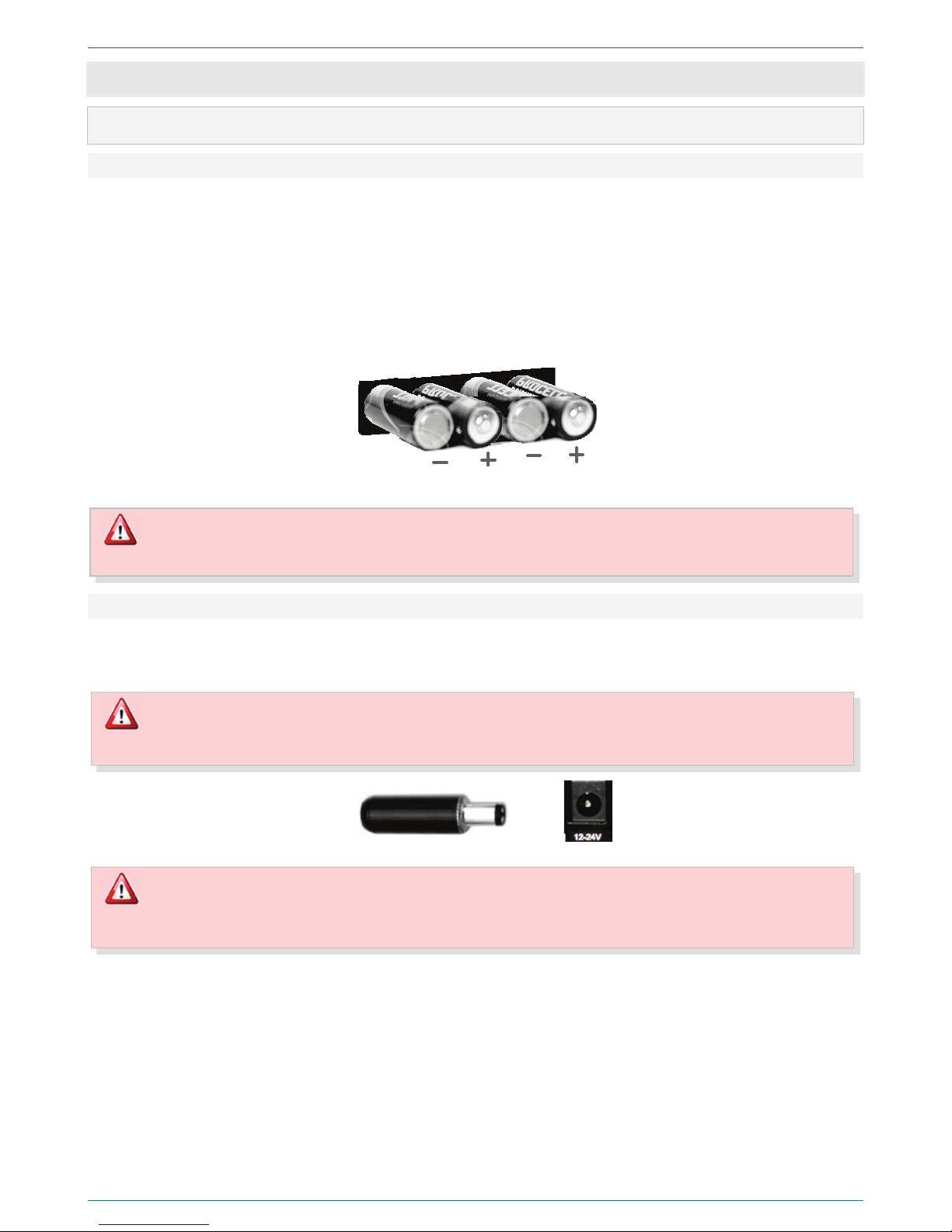
3. Remove old and place new batteries according to the polarity (figure 4).
4. Close the cover (figure 3, position 20).
5. Use the ON/OFF switch (figure 3, position 22) to turn on the device.
6. Check the software loading on the LCD.
Figure 4 – Batteries compartment. Inserting batteries
3.1.2 Connecting the device to the external power supply
Regulated power supply, with output voltage from12 to 24 V and allowable load current no less than 250 mА for 12 V and no
less than 125 mА for 24 V, is connected to 12-24 V socket (figure 3, position 19) on the device case. If the external power
supply is used, batteries supply will be automatically disabled.
Figure 5 – Socket for external power supply
You should use lithium batteries as an independent power supply.
Do not mix batteries of different types or from different manufacturers in one set.
To prevent the breakdown of the device, the socket (figure 5) of the direct current regulated source must have positive
potential on its central pin.
Use of third-party power source can damage the device. We recommend using the equipment from the delivery set.
The manufacturer is not responsible for device functioning when it is connected to third-party power source.

GETTING STARTED
11
3.2 Memory card
3.2.1 Suitable memory cards
Figure 6 – SDHC memory card
Recorded information is stored on removable nonvolatile SDHC (Secure
Digital High-Capacity) memory card with capacity up to 32 GB (figure 6).
For information storage, the FAT 32 file system is used.
You can find the list of compatible SDHC memory cards in appendix B.
3.2.2 Removing write protection
There is a LOCK switch on the left side card, which is used to prevent accidental information damage (figure 7).
To be able to write the information, slide the switch away from the LOCK position.
Figure 7 – Removing the write protection
3.2.3 Inserting memory card
After the
device is turned on and if memory card is not
inserted, in the lower part of the display
(figure 2, position 2
), you will see warning message
(figure 8).
Figure 8 – Insert memory card message
To insert memory card perform the following operations:
1. Use the ON/OFF switch to shut down the device (figure 3, position 20).
2. Remove the memory card protection (see p. 3.2.2).
3. Insert a card in the slot, watching the proper side (figure 10). Push the card in. You can hear a click when the card locks into
place.
4. Use the ON/OFF switch to turn on the device (figure 3, position 20).
After the device is turned on and the software is loaded,
you will see the message with the information about card
capacity and left space (figure 9) at the bottom part of the
screen (figure 2, position 2).
Figure 9 – Information about the card capacity and left space
Figure 10 – Inserting memory card

GETTING STARTED
12
3.3 Connecting headphones
You can use headphones to control the audio signal during the recording or playback. To connect the headphones use the
Headphones socket (figure 2, position 13), which is situated on the front panel of the device. The headphones must have
TRS cable (figure 11).
Figure 11 – Headphones socket
3.4 Connecting to digital inputs and outputs
Digital inputs and outputs are designed to interface with the systems of digital audio signals transmission using the S/PDIF
standard. To connect to the DIGITAL INPUT S/PDIF (Fig. 3, pos. 15) and to the DIGITAL OUTPUT S/PDIF (Fig. 3, pos. 16), the
cable fitted with the RCA header is used (Fig. 12).
Figure 12 – IPUT/OUTPUT sockets
Sampling rate applied to the input of signal should match the settings of the sampling rate on the device.
3.5 Connecting to line outputs
To connect the equipment to LEFT ANALOG OUTPUT and RIGHT ANALOG OUTPUT (figure 3, position 25 and 26) sockets,
use the TRS cable (figure 13).
Figure 13 – ANALOG OUTPUT sockets
3.6 Connecting to line inputs
To connect the equipment to LEFT ANALOG INPUT and RIGHT ANALOG INPUT sockets (figure 3, position 27 and 28), use
TRS (figure 14, А) or XLR cable (figure 14,B). XLR socket has a latch on the counterpart (figure 14,C). To unplug the cable use
the PUSH button.
А B C
Figure 14 – ANALOG INPUT sockets
3.7 Connecting to telephone line
Connection of the device to the telephone line is performed by breaking its connection with the telephone set. Connect the
telephone set to the FXO jack and the telephone line to the FXS jack (figure 3, position 17 and 18). Use standard TP-6P4C,
phone cable (figure 15). TP-6P4C phone cable has a latch. To unplug a cable, press on that latch.
Figure 15 – Jacks for a phone and phone circuit
GETTING STARTED
13
3.8 Connecting to local network
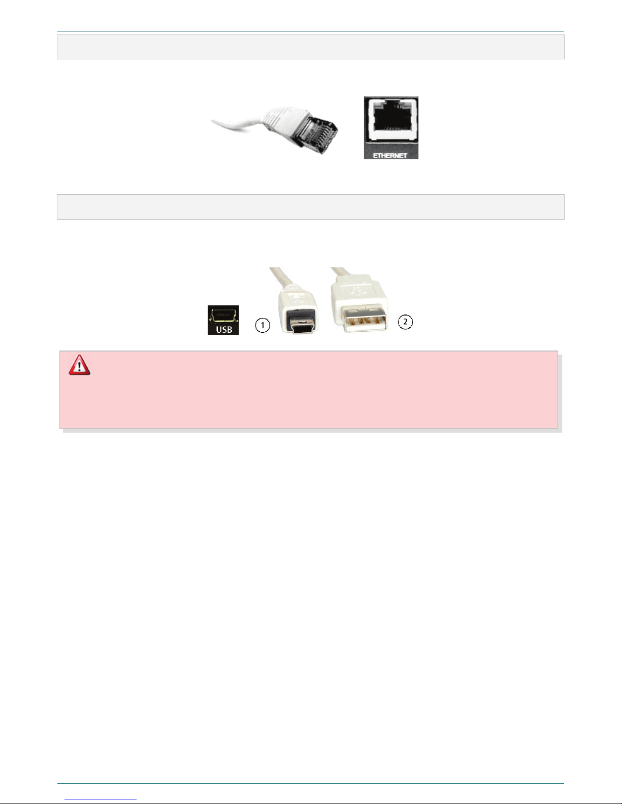
To connect the device to local network, use the ETHERNET jack (figure 3, position 24). For connection is used standard RJ45
cable (figure 16).
Figure 16 – Cable for connection to local network
RJ45 phone cable has a latch. To unplug a cable press on that latch.
3.9 Connecting to USB-port
You can connect the device to the PC through the USB port (figure 3, position 29). The connection is performed using the
standard 5-connector cable 1to connect to the MiniUSB (5 connectors) devices and socket 2, which is connected to the USB-
port of the PC (figure 17).
Figure 17 – Cable for the connection to the PC
Before the connection of the device to the PC, make sure that PC-case is grounded. Ground connection is essential
if you use simultaneous connection of the device to the PC and external power supply and (or) external signal
source. Non-observance of these requirements can cause device breakdown.
To ground the device, use the ground terminal (figure 3, position 19).
CONTROLS AND INDICATORS
14
4CONTROLS AND INDICATORS
4.1 Controls
4.1.1 Power switch
Use ON/OFF power switch (figure 3, position 22) on the back panel to turn power supply on and off. When the switch is set in
the ON position, the display will be turned on (figure 2, position 2).
4.1.2 Navigation buttons
Use navigation buttons , , , (figure 2, position 3) to move through the menu and select the proper menu
command or parameter within the limits of one level of menu multiple structure.
Press to set selected parameter or perform the selected menu command (including switching to the lower level of the
menu).
4.1.3 MENU button
Press the MENU button (figure 2, position 4) to go to the higher level in menu structure without saving any changes, if they
have not been saved by pressing .
4.1.4 RECORD button
Press the RECORD button (figure 2, position 6) to turn the recording mode on or off.
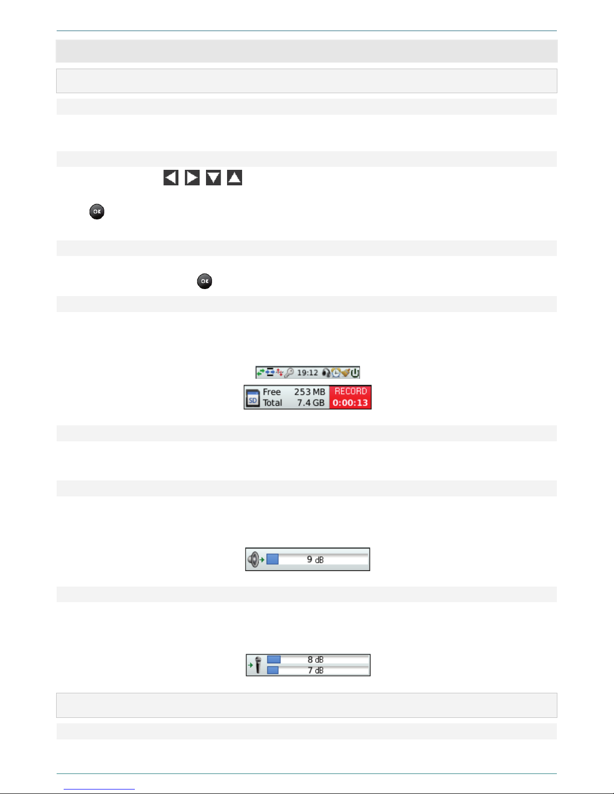
Press the RECORD button to begin the recording; it also turns on the backlit of the button. The recording process activity will
be indicated by the word RECORD and recording time at the left bottom corner of the display (figure 18).
Figure 18 – Recording process indication
4.1.5 MONITOR button
Press the MONITOR button (figure 2, position 5) to turn the listening of the point-to-point channel on or off.
Press the MONITOR button to begin the monitor; it also turns on the backlit of the button.
4.1.6 Volume control
Use VOLUME control (figure 2, position 1) to adjust volume level during audio records playback through the built-in speaker
or headphones. When the playback is turned on, you can see the adjusted volume settings (figure 19) at the bottom part of
the display (figure 2, position 2).
Figure 19 – Volume settings
4.1.7 Controls of the left and right channels
Use controls of left and right channels (figure 2, position 7 and 9) to set the required signal level on recording channels. If the
recording mode is on, you can see the adjusted signal levels for each channel (figure 20) at the bottom part of the display
(figure 2, position 2).
Figure 20 – Left and right channels value
4.2 Indicators
4.2.1 LCD
The LCD (figure 2, position 2) resolution is 176х220. On the display, you can see the information about device operation,
parameters, commands, and levels of the menu.
CONTROLS AND INDICATORS
15
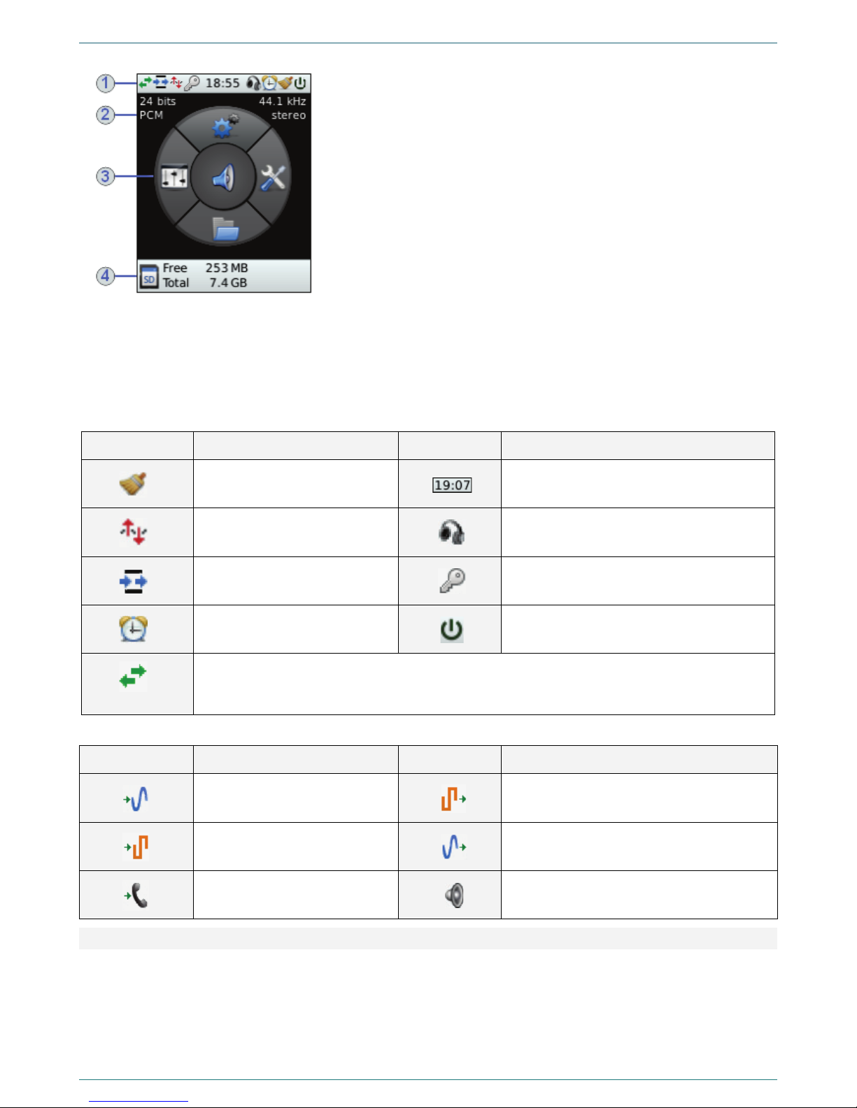
You can see the LCD and main menu of the system in the figure 21.
Figure 21 – LCD and main menu
There are four sections of the LCD:
1 – In that section, you can see icons, which show parameters of the current
working mode.
2 – In that section, you can see parameters of current recording format.
3 – In that section, you can see main menu of the device and its mnemonic
match to five navigation buttons (figure 2, position 3).
Press the proper navigation button to see parameters and commands of the
lower level of the menu in parts 2 and 3.
When you open the Lines selection menu, you can see icons of the currently
used inputs and outputs of the device.
4 – This part changes its content according to the working mode. Here, you
may see SD-card capacity (see figure 9); recording process and time (see
figure 18); amplification value during the recording (see figure 20) or
playback (see figure 19).
In the tables 3 and 4, you can see the information about icons, which are located in sections 1and 3and are used to indicate
parameters and working modes of the device.
Table 3 – Icons of the section 1
Icon Description Icon Description
Batch noise reduction is on Current time
Voice activation is on Headphones connected
Point-to-point channel is on PIN code protection is active
Timer is on External power source connected
Switching the channels during the playback (monitor or file) to the left/right/mix. The option is
available only if the sound comes through headphones/built-in dynamic. To adjust that parameter
press volume control.
Table 4 – Icons of the Lines selection section
Icon Description Icon Description
Recording from line input Playing to lines of digital output
Recording from digital input Playback to external lines of line output
Record from telephone line Playback to headphones/built-in speaker
4.2.2 Indicators of the recording level
Indicators of the recording level (figure 2, position 10) are two rows of LEDs (light-emitting diodes) on the front panel of the
device. The glow of certain green LEDs indicates relative value of the recording level. The glow of the last two LEDs indicates
the exceeding of normal signal level and possible distortion of recorded signal.

MULTILEVEL MENU
16
5MULTILEVEL MENU
5.1 Multilevel menu structure
Using navigation buttons (figure 2, position 3), you can open the following menus (figure 22):
1. Filters–
2. Browse SD-card –
3. Settings –
4. Utilities –
5. Lines selection –
Figure 22 – Navigation buttons and menus
Use the MENU button (figure 2, position 4) to go back to the higher level of the menu. To return to the main menu, press this
button required number of times.

MULTILEVEL MENU
17
5.2 Navigation order in the multilevel menu
In the figure 23 you can see an example of the navigation through the multilevel menu.
Press to open the Lines selection menu. Use and buttons to select the required menu command. For
example, Input source.
Press to open the Input source menu. Use and buttons to select the required output. For example, Internal
microphones. To confirm the selection, press .
After that, press the MENU button twice to return to the main menu.
Figure 23 – Example of navigation through multilevel device menu
This manual suits for next models
1
Table of contents


