Speechi SPE-310W-I-T User manual

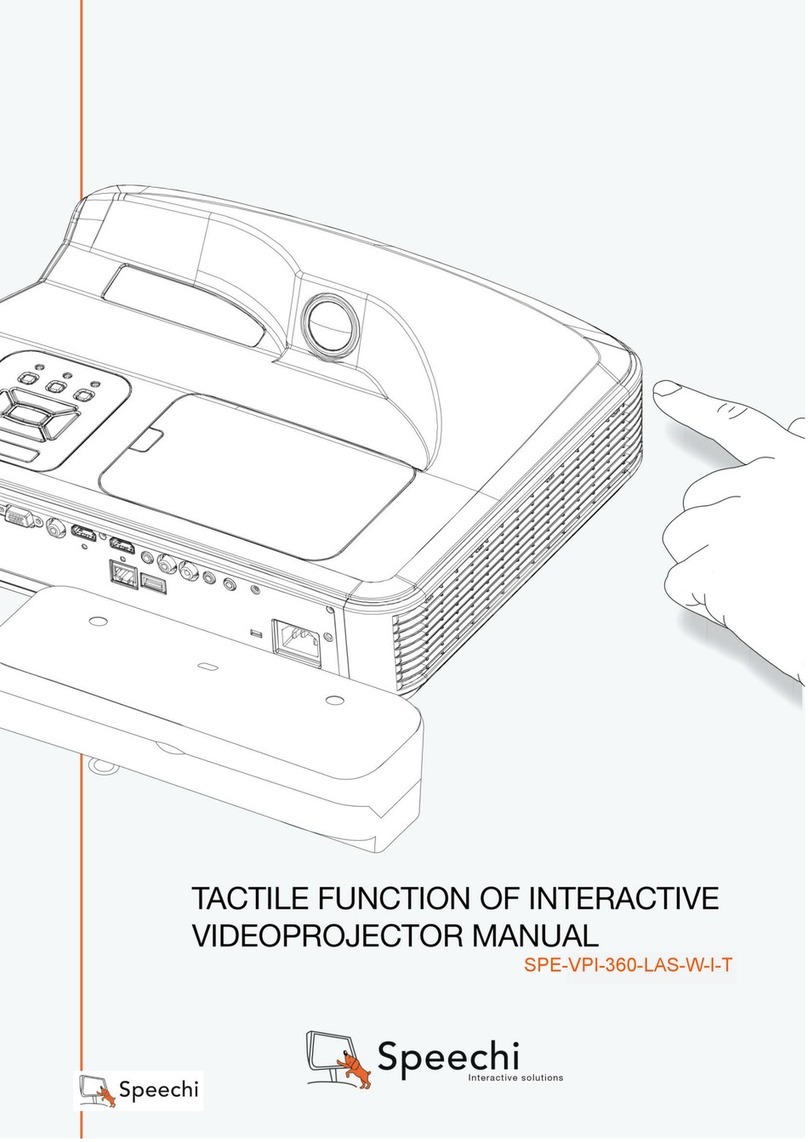
TACTILE FUNCTION OF INTERACTIVE
VIDEO PROJECTOR MANUAL
SPE-310W-I-T

1
Table of Contents
Usage Noce ........................................................................................................................................ 2
Light Curtain Touch .............................................................................................................................. 3
Light Curtain Touch Set-up................................................................................................................... 4
Step 1:Projector Set-up ....................................................................................................................... 5
Step 2: Light Curtain and Whiteboard Set-up...................................................................................... 6
Step 3: Install Driver........................................................................................................................... 10
Step 4: Touch Area Seng................................................................................................................. 11
Step 5: Laser Beam Adjustment......................................................................................................... 15
Step 6: Calibraon.............................................................................................................................. 21
Step 7: Mode Selecon ...................................................................................................................... 22
Step 8: Touch Sensivity .................................................................................................................... 23
Step 9: Applicaon ............................................................................................................................. 24
Trouble-shoong................................................................................................................................ 25

2
Usage Notice
Please follow all warnings, precautions and maintenance as recommended in this user's manual.
Warning - Do not disassemble Light Curtain module/IR camera.
Warning - Do not use, store, or leave Light Curtain module/IR camera near fire, or in
places with a high temperature, e.g., in direct sunlight, or in sun-heated cars.
Warning - Use standard USB cable(maximum length: 5m). To extend USB cable length
over 5m, a certified active extension USB cable is required.
Warning - Do not allow liquid or foreign material enter Light Curtain module/IR camera
Precautions
IR camera on projector receives infrared signal from Light Curtain module which is attached to
the wall.
To operate normally:
IR camera should face the projection image area on the wall.
Remove any obstacle in between IR camera and Light Curtain module.
Do not place other infrared communication devices, lighting equipments, or residential
heating equipments etc, nearby.
Maintenance: Gently clean the optical port with dust blower.

3
Light Curtain Touch
How it works
Light Curtain covers the entire whiteboard with a thin invisible IR light.
When finger or stylus breaks into the Light Curtain, IR light reflects to IR camera.
Camera module tracks multiple touch points and reports positions to a PC or laptop via
USB.
To optimize Touch function, whiteboard non-flatness should be less than 5mm.
IR Camera module
Light Curtain module
Whiteboard
Interactive cable

4
Light Curtain Touch Set-up
AC Power
Display by VGA or HDMI
Projector Lens USB
Interactive
cable
IR Camera IR Camera
Light Curtain Light Curtain
IR Light Curtain Illumination
Image
Scattering light
Whiteboard

5
Step 1: Projector Set-up
A. Plug in IR Camera Module
B. Install Wall Mount and Projector
Step 1
Remove the
corner cover
Step 2
Plug in IR
camera module

6
Step 2: Light Curtain and Whiteboard Set-up
A. Setup Light Curtain Base Plate
There are 4 available options:
1. For magnetic whiteboard: attach Curtain base plate to Light Curtain module first and avoid
interlock switch fail. Put Light Curtain module onto whiteboard and magnets at the back of
Curtain module will be attached.
2. Install Light Curtain base plate by using 2 M3 screws
Option 2 is recommended regarding environmental factors such as temperature,
humidity, vibration and others.
2-1. Customized whiteboard is incorporated with Light Curtain base plate design.
2-2. Regular whiteboard, the Light Curtain base plate needs to be installed first by using 2
M3 screws.
Magnets
Interlock Switch
Projection Image
gap: 48~98mm
Light Curtain base plate (for mounting Light Curtain)
Mount Light Curtain base plate by
using 2 M3 screws
Center of White Board

7
3. Use special glue(ex: AB glue) to adhere Curtain base plate to the whiteboard. Then place
Light Curtain module onto Curtain base plate.
4. This option is suitable for demonstration ONLY.
Use a piece of good quality double-sided adhesive (thickness less than 0.5mm) to adhere
Curtain base plate onto the whiteboard. Then place Light Curtain onto the Curtain base
plate.
B. Whiteboard frame suggestion
If whiteboard frame thickness is over 3mm, reflected light interference from whiteboard frame
may be detected by IR camera and influence Touch function. It is suggested to keep at least
50mm at left/right and 100mm at bottom.
Adhere
Adhere Curtain base plate to the whiteboard with AB glue,
then place Light Curtain onto Curtain base plate.
Use a good piece of double-sided adhesive
(thickness ≤0.5mm) to adhere Curtain base
plate onto whiteboard.
Attach Light Curtain onto Curtain
base plate on the whiteboard.

8
If whiteboard frame thickness is less than 3mm, ensure reflected light interference is not
observed while doing Step 5 Laser Beam Adjustment.
Therefore, it is suggested to use whiteboard frame less than 3mm, or follow below whiteboard
frame condition:
-Surface treatment: Matt , with mold texture ≥11010
-Shape: as figure below
C. How to Setup whiteboard
Frame
White board
IR CAMERA
>3mm
≤3mm
Frame
White board
IR CAMERA
NG OK
10mm
White board
Frame
Projection Image
25mm
≦45°
≧10mm
( Image Area: 75”~100” @WXGA)
gap: 20~70mm
Fromthe top of image area, a gap must be kept 20mm~70mm away
the bottom of light curtain.
For suggested frame design whiteboard, it is suggested to keep
10mm bezel at Left / right / bottom for Win8 requirement.
For regular frame design whiteboard, it is suggested to keep at
least 50mm at left /right and 100mm at bottom, to prevent
reflected light interference from whiteboard frame.
White board frame
~bezel ~bezel
~bezel
Light Curtain

9
D. Install Light Curtain Module on whiteboard.
1. Open top cap.
2. Align the M4 screw hole to the Curtain base plate; magnets at back of Light Curtain module
will attract Curtain base plate.
3. Use one M4 screw to fix Light Curtain module and Curtain base plate
4. Close top cap.
M4 Screw

10
Step 3: Install Driver
1. System requirements
To ensure normal operation of the touch function, follow below requirement to check your
system condition.
System requirement
Operating system
Microsoft Windows XP (SP3)/Windows 7 (32bit/64bit)/Windows 8
(Must be installed. NET Framework 4.0)
CPU
Intel® Core™ i3 or above
Memory
2GB or more
Minimum hard disk
space
110 MB
2. Install TouchDriver
A. Plug in USB cable to PC, go to Windows File Manager and run “TouchDriver.exe” on CDROM.

11
Step 4: Touch Area Setting
There are two Touch Area Setting modes: Auto and Manual.
A. Execute Auto Touch Area Setting:
If fail message pops up, follow below steps to trouble-shoot and re-run Auto Touch Area
Setting:
a. Quit all software application
b. Reduce ambient light
c. Do not obstruct or shake lens during Touch Area Setting
d. Check if projection image is clear. If not, adjust focus to sharpen the image
If the fail message still pops up, switch to Manual Touch Area Setting.
B. Touch Area Setting is for installer use only. If Auto Touch Area Setting fails:
Switch “ON” Installation mode(this is for installer use only) under System Setting in
TouchDriver.

12
Select “Manual” to execute the Manual Touch Area setting.
B-1. Wait for Touch Area Setting test pattern.
B-2. After the camera captures the projection image, a Touch Area window will pop up. If
the captured image is not clear enough, please re-select “Ambient light mode
selection” from “Auto” to “Bright” or “Dim” according to actual ambient light
condition. Then press “Preview” and the camera will re-capture the image.

13
B-3. Touch Area Boundary Fine-tuning
Step 1: Click on P1 then move the mouse cursor within the window.
Step 2: Left click the mouse to adjust the green frame at the P1 corner. The green
frame should locate between the effective projection area and reflected light
spots of whiteboard frame. Release the button when adjustment is done.
Step 3: Use the same method to adjust green frame at P2, P3 and P4.
Step 4: Finally, check again if all the green frame locate correctly in the designated
area. If not, adjust again.
Note: If Touch function is not responding at the edge of projection area, slightly re-
locate the green frame outside of Touch Area test pattern.
B-4. Exit Touch Area Setting
When the Touch Area is delineated, click to “Exit.”

14

15
Step 5: Laser Beam Adjustment
A. Purpose
Reflection of alignment bar: Three white blocks reflect Laser beam. Black area is non-reflective.
B. Initiate “Laser Beam Adjustment” function
Switch “ON” Installation mode(this is for installer use only) under System Setting in
TouchDriver.
or
Laser
Laser
Laser

16
The function of “Laser Beam Adjustment” displays a real time image from IR camera.
C. Attach the Alignment Bars:
This is a full-screen image with alignment bar positions indicated to be attached.
Light Curtain
Alignment bar R3
Alignment bar R2
Alignment bar R1

17
D. How to Adjust Laser Beam:
D-1 Open the Top Cap:
Open the top cap of Light Curtain module. There are 6 screws with 6 corresponding
positions of alignment bars.
D-2 Plug in Interactive cable.
D-3 How to adjust when Laser beam is too high or low
Good
Whiteboard
Counterclockwise, lower Laser beam
Acceptable (Lower)
Whiteboard
Clockwise, lift Laser beam
Acceptable (Higher)
Single spot
Laser beam too high
Light bar
Laser beam too low
Interactive Cable
(DC power)

18
D-4 Right-hand side adjustment order:
1. Attach alignment bars
2. Adjust screws in the order of R1→R3→R2.
a. Adjust R1 screw until 3 light spots appear at bar R1.
b. Adjust R3 screw until 3 light spots appear at bar R3.
c. Finally, adjust R2 screw until 3 light spots appear at bar R2.
d. Fine-adjust if necessary.
e. Remove alignment bars.
When the screw ties or sounds 'cluck', stop and see Question 7 for trouble-shooting.
Whiteboard
Single spot without halo
Clockwise, lift Laser beam
Whiteboard
Counterclockwise, lower Laserbeam
Good or Acceptable
Halo examples

19
D-5 Left-hand side adjustment order:
1. Attach alignment bars
2. Adjust screws in the order of L1→L3→L2.
a. Adjust L1 screw until 3 light spots appear at bar L1.
b. Adjust L3 screw until 3 light spots appear at bar L3.
c. Finally, adjust L2 screw until 3 light spots appear at bar L2.
d. Fine-adjust if necessary.
e. Remove alignment bars.
Alignment bar R3
Alignment bar R1
Alignment bar R2
OK
Other manuals for SPE-310W-I-T
1
Table of contents
Other Speechi Projector manuals
