Speed Passion REVENTON S User manual


V1.1 Creation on Jan13th2012
King‐GoldenLimited
CONTENTS
1. ReventonESCFeatures……………………………………………………………………………..Page1
2. Specifications…………………………………………………………………………………………….Page1
3. ESC’sindicatingLEDs………………………………………………………………………………….Page6
4. WiringDiagram………………………………………………………………………………………….Page7
5. ThrottleRangeSetting/Calibration……………………………………………………………..Page8
6. TheLEDStatusinNormalRunning……………………………………………………………...Page8
7. ProtectionFunction…………………………………………………………………………………...Page8
8. TroubleShooting………………………………………………………………………………………….Page9
9. OptionalUpgradeAccessories…………………………………………………………………….Page10
10.ProgrammingtheESC………………………………………………………………………………..Page10
11.ProgramStockClubRaceESC……………………………………………………………………..Page13
12.ProgrammableItemslist……………………………………………………………………………..Page14
13.ESCProductWarrantyPeriod………………………………………………………………….….Page23

ReventonSeriesBrushlessMotorSpeedControllerManual
ThankyouforpurchasingtheSpeedPassionREVENTONserieselectronicspeedcontroller(ESC).HighpowersystemsforRC
modelscanbeverydangerous.Usersshouldreadthismanualcarefully.SpeedPassionhasnocontroloverthecorrectuse,
installation,application,ormaintenanceofourproducts.Noliabilityshallbeassumednoracceptedforanydamages,lossesor
costsresultingfromtheuseoftheproduct.AnyclaimsarisingfromthefailureoftheESC,malfunctioningetc.willbedenied.
SpeedPassionassumesnoliabilityforpersonalinjuryorconsequentialdamagesresultingfromourproductsorourworkmanship.
Asfarasislegallypermitted,theobligationtocompensationislimitedtotheinvoicedamountoftheaffectedproduct.
1. ReventonESCFeatures:
TheReventonESCissuitablefor1/1 0 thscaleonroadandoffroadvehicles.
◆ Compatiblewithallsensoredandsensorlessbrushlessmotors.
◆ BuiltinESCenhancementfeaturewillallowuserstoupdatetothelatestDRRSVersion3.0softwareandanyfuture
softwaredevelopments.
◆ New“Reventon‐DynamicSensorTechnologySeries”feature.Stateoftheart,newdevelopmentinsoftwarewill
giveusersmaximumefficiencyalongwithawidepowerbandforconsistentperformanceandmaximumpower
output!
◆ ProportionalABSbrakefunctionwith9stepsofbrakeadjustment.9stepsofAutodrag‐brakeadjustment.
◆ NewDigitalRacingResponsemodesVersion2.0(FromLevel1‐SmoothtoLevel9‐Aggressive)“DigitalRacing
ResponseSystem–DRRS3.0”(note1).Fullyupgradeablefordifferentmodesandlevelsoftuning.
◆ Multiplesafetyprotectionfeatures:Lowvoltagecut‐offprotectionforlithiumbatteries/Over‐heatprotection/
Throttlesignallossprotection/Lockedmotorprotection.
◆ New“DynamicMultiTimingSystem‐DMTS”TomaximizemotorandESCperformance,theReventonESChasa
special8modeadjustmentsystemdesignedforanybrandofbrushlessmotor.
◆ 3runningmodes(Forwardwithbrake“NoReverse”,Forwardwithbrake“reverseafterFULLStop”andDirect
Forward/reversewithbrake)(note2).
◆ Fourbuttonsforeasyprogramming.Compatiblewithpocket‐sizedUSBSMARTESCprogramunit.
2. Specifications:
Reventon‐S/Reventon‐R/StockClubRace–ReventonESCFeatureList
ModelReventon‐SReventon‐R
Continuous/Burst
Current
40A/250A70A/440A
Resistance0.0005ohm0.0003ohm
Maximum
Battery(note5)
4‐9CellNi‐xx(NiMhorNiCd)or
2CellLi‐Po/2to3CellLi‐Fe
For4‐6CellNi‐xxor2sLipo:Usethe
standardfansuppliedwiththeESC;
For7‐9CellNi‐xx:TheincludedESCfanis
notcompatiblewithhighvoltage.ESCfan
mustbereplacedwithahighvoltagefan
orconnectthefantothereceiverport
(+5V).(note4)
4‐9CellNi‐xx(NiMhorNiCd)or
2CellLi‐Po/2to3CellLi‐Fe
For4‐6CellNi‐xxor2sLipo:Usethe
standardfansuppliedwiththeESC;
For7‐9CellNi‐xx:TheincludedESCfanisnot
compatiblewithhighvoltage.ESCfanmustbe
replacedwithahighvoltagefanorconnectthe
fantothereceiverport(+5V).(note4)
BECOutput6.0V/BEC2A6.0V/BEC2A
ESCTypeSensored/SensorlessSensored/Sensorless
MotorTypeSensorlessorsensoredbrushlessmotorSensorlessorSensoredbrushlessmotor
Dimensions33mm(L)x33mm(W)x19mm(H)
w/ocoolingfan
33mm(L)x33mm(W)x19mm(H)
w/ocoolingfan
BrushlessMotor
Limit
9.5Torslower(note3)5.5Torslower(note3)
ESCFan25MM25MM
SupportsWi‐Fi
Modulesoftware
upgrade(note7)
Yes(optionalWi‐Fimodulesold
separately)
Yes(optionalWi‐Fimodulesoldseparately)

V1.1 Creation on Jan13th2012
King‐GoldenLimitedPage1
SupportsSmartLED
programcardwith
USBsoftware
upgrade
YesYes
Supports2.4G
held‐setfor
programsetting
Yes(optional2.4Gheld‐setprogrammer
soldseparately)
Yes(optional2.4Gheld‐setprogrammersold
separately)
SupportsBluetooth
modulesoftware
upgrade(note6)
Yes(optionalBluetoothmodulesold
separately)
Yes(optionalBluetoothmodulesold
separately)
Temperature
display(note2,8)
YesYes
Batteryvoltage
display(note2,9)YesYes
RacingProfile
Settings
Drift1,Modified0,Modified1,Rock
Crawler,andStock0.
Drift1,Modified0,Modified1,RockCrawler,
Stock0,andStock1.
Note1:ForReventonversion,NewDigitalRacingRespondSystem(FromLevel1‐smoothtoLevel9‐
aggressive)“DigitalRacingResponseSystem–DRRS3.0”.
Note2:LEDprogramcard,Bluetoothmodule,orWi‐Fimodulearerequiredtodisplaythe
temperatureoftheESC.
ModelReventon–StockClubRace
Continuous/BurstCurrent40A
/
250A
Resistance0.0005ohm
Battery(note5)4‐9CellNi‐xx(NiMhorNiCd)or
2CellLi‐Po/2to3CellLi‐Fe
For4‐6CellNi‐xxor2sLipo:Usethestandardfansupplied
withtheESC;
For7‐9CellNi‐xx:TheincludedESCfanisnotcompatiblewith
highvoltage.ESCfanmustbereplacedwithahighvoltagefanor
connectthefantothereceiverport(+5V).(note4)
BECOutput6.0V/BEC2A
ESCTypeSensored/Sensorless
MotorTypeSensorlessorsensoredbrushlessmotor
Dimension33mm(L)x33mm(W)x19mm(H)
w/ocoolingfan
BrushlessMotorLimitMax>8.5T (note3)
ESCFan25MM
SupportsWi‐FiModulesoftwaresetting(note10) Yes(optionalWi‐Fimodulesoldseparately)
SupportsSmartLEDprogramcardforprogram
setting(note12)
Yes(optionaldevice)Note:SmartLEDprogramcardsold
separately
Supports2.4Gheld‐setforprogramsettingNo
SupportsBluetoothmodulesetting(note11)Yes(optionalBluetoothmodulesoldseparately)
Temperaturedisplay(note2,8)Yes
Batteryvoltagedisplay(note2,9)Yes
RacingProfilesettingStock0–“ZeroTimingSoftware”

V1.1 Creation on Jan13th2012
King‐GoldenLimitedPage2
Note3:Thebrushlessmotorlimitistestedunderthefollowingconditions:
a)Theinputisa6cellNi‐xxbattery;b)TheESCisequippedwithafan.
Note4:ThevoltageoffansocketontheESCisequaltothevoltageofthebattery.Itisdirectly
suppliedwithoutanyregulation.PleasekeepinmindthatthevoltageofbatteryCANNOT
exceedthevoltagelimitofthefan,7.2V.
Note5:Forbrushlessmotors,theESCsupportsupto8cellNiMh/NiCd(or3cellsLi‐Fe)input.
Note6:ForReventonRandSversion,TheESCsupportstheBluetoothmodule.Theusercanmodify
theESCsettingsbyusingasmartphone.Furthermore,userscandownloadthelatest
firmwareandupdatesfortheESC.
Wi‐FiModuleBluetoothModule
Note7:ForReventonRandSversion,TheESCsupportstheWi‐Fimodule.Theusercanmodifythe
ESCsettingsbyusingasmartphone.Furthermore,userscandownloadthelatestfirmware
andupdatesfortheESC.
Note8:Thedisplayofbatteryvoltageisforreferenceonly.
Note9:Thedisplayoftemperatureisforreferenceonly.
Note10:ForStockClubRaceversion,TheESCsupportstheBluetoothmodule.Theusercanmodify
theRCcarsettingbyyourAndroidphone/Tablet,“AndroidOS2.2above”.
Note11:ForStockClubRaceversion,TheESCsupportstheWi‐Fimodule.TheusercanmodifytheRC
settingbyyouriPhone/iPad/iPodtouchiOS4.1above.
Note12:ForStockClubRaceversion,TheESCsupportstheLEDprogramcard.Theusercanonlyuse
theLEDprogramcardtochangethesetting.ItwillnotconnecttoPCoraltertheracing
softwareprofiles.

V1.1 Creation on Jan13th2012
King‐GoldenLimitedPage3
Table1:RacingfirmwarefeaturelistingforREVENTONESC
Item Description Drift1 Rock Crawler Modify1 Modify0 Stock0 Stock1
Running mode √√√√√√
Forward with brake " No reverse" √√√√√√
Forward /reverse with brake √√NA √NA √
Forward with reverse NA √NA NA NA NA
Forward with reverse after " FULL STOP" NA √NA NA NA NA
Threshold Voltage/Cell LiPo Cut-off √√√√√√
Dynamic Multi Timing System - DMTS 3.0 (Boost Timing) √√√√NA √
Digital Racing Response System-DDRS 3.0 √√√√√√
Percentage Braking-ABS √√√√√√
Percentage Drag Braking √√√√√√
Throttle Percent Reverse √√√√√√
Neutral Range √√√√√√
Over Heat Protection √√√√√√
Motor rotation (CW/CCW) NA NA NA NA NA NA
Supercharger slope Rate NA NA NA NA NA
√
Supercharger Timing NA NA NA NA NA
√
Boost Start RPM NA NA NA NA NA
√
Supercharger Delay NA NA NA NA NA
√
Boost Timing Acceleration NA NA NA NA NA
√
ESC Temperature √√√√√√
Battery Voltage √√√√√√
ESC Firmware √√√√√√

V1.1 Creation on Jan13th2012
King‐GoldenLimitedPage4
3. ESC’sindicatingLEDs:
*WhentheESCisconnectedtothebatteryandturnedon,theESCcanautomaticallyidentifythemotor
type(Sensored/Sensorless)viatheindicatorLED.
*IftheESCisinSensoredmode,removethesensorwireandtheESCwillautomaticallychangeto
Sensorlessmode.
Sensored/SensorlessESC’sindicatorLED
StatusINDICATORLEDStatusoftheLED
LowbatteryvoltageRedLEDBlinking
Over‐heatingofESCandmotor
(95℃)YellowLEDBlinking
SensoredmotorRedandYellowLEDON
SensorlessmotorYellowLEDON
SensorlessESC’sIndicatingLED
FunctionIndicatingLEDLEDStatus
LowbatteryvoltageRedLEDBlinking
Over‐heatingofESCandmotor
(95℃)YellowLEDBlinking
SensorlessmotorYellowLEDON
UsingtheReventonESC
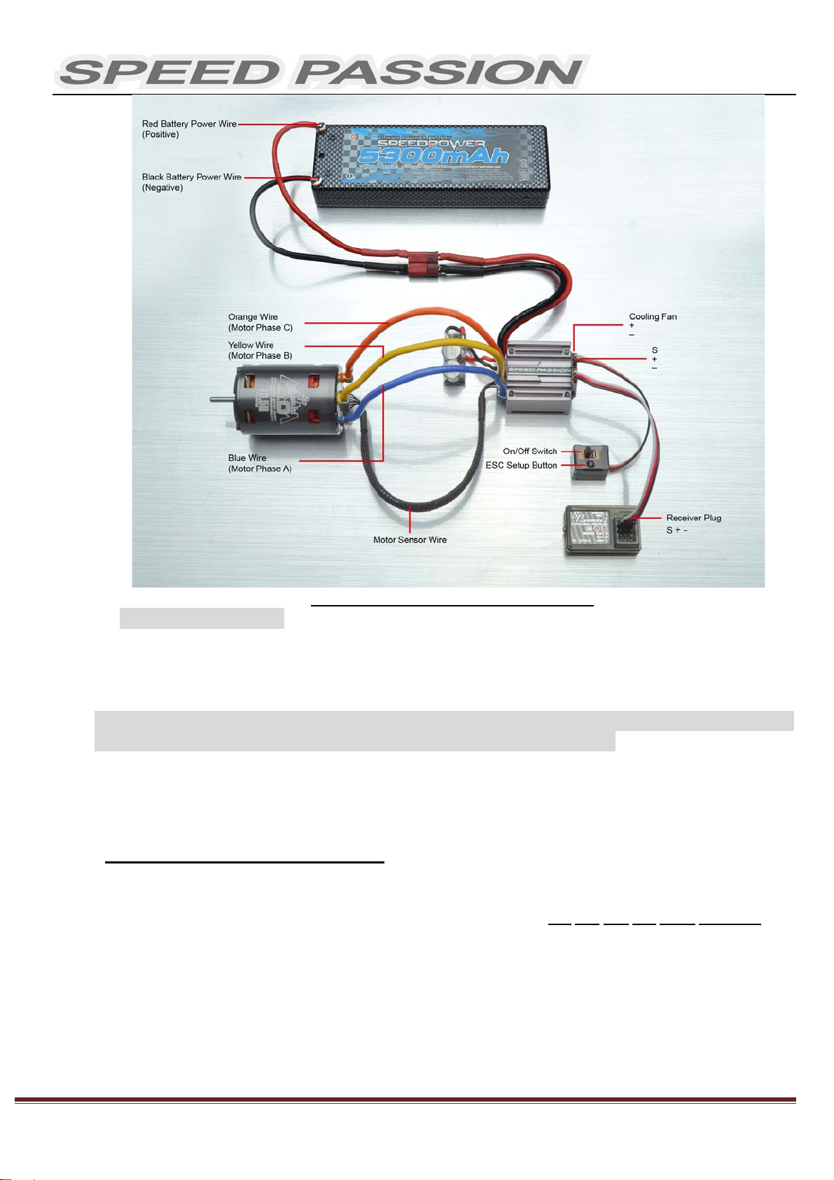
4. WiringDiagram:
4.1 ConnecttheESC,motor,receiver,batteryandservoaccordingtothediagrambelow.
Positive“+”andNegative“‐”wiresontheESCareconnectedtotherespectivepositiveandnegative
terminalsonthebatterypack.MotorwiresA,BandCaretobeconnectedtorespectiveterminalsonthe
motor.The“SET”buttonisusedforprogrammingtheESC.The“Fan”connectorisusedtosupplythe
coolingfan.
ThereceivercableoftheESC(black,redandwhitecoloredwires)isconnectedtothethrottlechannelof
thereceiver(UsuallyCH2).
NOTE:TheCapacitorMUSTbeconnectedtothePositive(+)andNegative(‐)terminalsoftheESC.
DAMAGEWILLOCCURIFTHECAPACITORISNOTCONNECTED!
V1.1 Creation on Jan13th2012
King‐GoldenLimitedPage5
PictureA:Wiringwithabrushlessmotor
4.2 BrushlessMotorWiring
Connectingtoasensoredbrushlessmotor
Whenusingasensoredmotor,itisnecessarytoconnectthesensorcabletothe“SENSOR”socketon
theESCandthesensorportonthemotor.TheESCcanautomaticallyidentifythemotortype
(sensoredorsensorless)bydetectingthesignalcomingfromtheSENSORsocket.
WARNING!Whenusingasensoredbrushlessmotor,theA,B,CwiresoftheESCMUSTconnect
withthemotorwireA,B,Crespectively.Donotchangethewiresequence!
Connectingtoasensorlessbrushlessmotor
WhenusingabrushlessmotorwithoutaHallSensor,the#A,#B,#CwiresoftheESCcanbeconnected
withthemotorwiresinanyorder.Ifthemotorrunsbackwards,swapanytwoofthemotorwire
connections.
5. ThrottleRangeSetting/Calibration
InorderfortheESCtorecognizethetransmitterthrottlerange,theESCmustbecalibratedit.TheESC
mustbecalibratedwhensettingupanewESC,usinganewtransmitter,orchangetheATVorEPAsettings
oftheradio.TheESCmustbecalibratedaftereachfirmwareupdateortheESCwillnotworkproperly.
Thereare3pointsthatneedtobeset,“fullthrottle”,”fullbrake”andtheneutralpoint.
ThefollowingpicturesshowhowtosetthethrottlerangewithaFutabaTMtransmitter.

V1.1 Creation on Jan13th2012
King‐GoldenLimitedPage6
6. TheLEDStatusinNormalRunning
Innormaluse,ifthethrottleisattheneutralsettingandthesensorcableisconnected,theredLEDand
theyellowLEDwillbelit.
TheredLEDlightsupandwillflashwhentheESCsensesalowinputvoltage.
TheyellowLEDlightsupandwillflashwhentheESCoverheating(over95℃).
Alertsignal
6.1 Abnormalinputvoltagealerttone:
TheESCcheckstheinputvoltagewhenpoweredon.Ifitisoutofthenormalrange,theredLED
willbeginflashing.
7. ProtectionFunction
7.1 Lowvoltagecut‐offprotection:
7.1.1Ifthelithiumbatterypack’svoltageislowerthanthevoltagethresholdfor2seconds,theESC
willcutpoweroutput.PleasenotethattheESCcannotberestartedifthevoltageofeachlithium
cellislowerthan3.5V.Userscandisablecutoffvoltageprotectionfunctionforcompetitiveracing.
7.1.2ForNiMh/NiCdbatterypacks,ifthevoltageoftheNiMh/NiCdbatterypackishigherthan12V,
itwillberecognizedasa4celllithiumbatterypack.Ifitishigherthan9.0V,butlowerthan12V,it
willberecognizedasa3celllithiumbatterypack.Ifitislowerthan9.0V,itwillberecognizedasa2
celllithiumbatterypack.Forexample,aNiMhbatterypackmeasuring8.0Vandthevoltage
thresholdissetto2.6V/Cellwillberecognizedasa2celllithiumbatterypack.Thelowvoltage
cut‐offforthisNiMhbatterypackwillbe2.6Vx2=5.2V.
7.2 Over‐heatprotection:WhenthetemperatureoftheESCisover95℃for5seconds,theESCwill
cutpoweroutput.Userscandisableover‐heatprotectionfunctionforcompetitiveracing.
7.3 Throttlesignallossprotection:TheESCwillcutpoweroutputifthethrottlesignalislostfor0.2
second.
A) Ensure the ESC is switched off. Turn
on the transmitter.
B) Set the direction of throttle channel
to”REV” (ONLY for Futaba Radios),
set the “EPA/ATV” value of throttle
channel to “100%”.
C) Use a pen or screwdriver to press and
hold the “SET” button and then switch
on the ESC. Release the “SET” key
when the red LED begins to flash.
D) Set the 3 points according to the steps
shown in the picture to the left
a) Neutral point
b) Full throttle
c) Full brake
E) When the calibration process is
completed, the motor can be started
after 3 seconds
(Please refer to the figures to the left)
V1.1 Creation on Jan13th2012
King‐GoldenLimitedPage7
8. TroubleShooting
AlwaysstarttroubleshootingbyresettingtheESCtothethrottlerangeofthetransmitter.Calibrationwill
mostlikelysolvetheissue.(Throttlerangecalibrationabove)
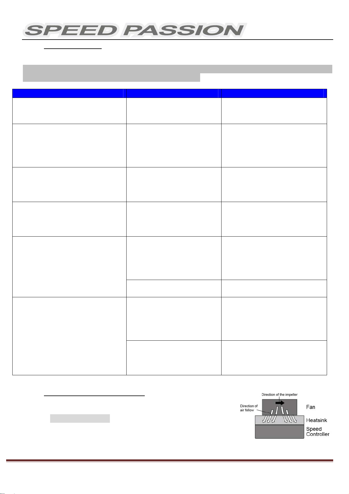
9. OptionalUpgradeAccessories
SpeedPassionprovidesthefollowingaccessoriestoupgrade
theReventonESC:
9.1 Heatsinkfan(8V):The8Vfanisnecessarywhenusing
batterypacksthataremorethan6cellNiMh/NiCdor2sLipo.
ItismountedtotheheatsinkoftheESC.Ithelpstocoolthe
ESCwithdownwardairflow.Thepictureontherightside
showstheinstallation.
TroublePossibleReasonSolution
AfterESCispoweredon,motor
doesn’twork,nosoundisemitted
Theconnectionsbetween
batterypackandESCarenot
correct
Checkthepowerconnections
Replacetheconnectors
AfterESCispoweredon,motorwon’t
work,butemits“beep‐beep‐,
beep‐beep‐”alerttone.(Every
“beep‐beep‐”hasatimeintervalof1
second)
Inputvoltageisabnormal,too
highortoolow.
Checkthevoltageofthebattery
pack
AfterESCispoweredon,motorwon’t
work,butemits“beep‐,beep‐,
beep‐”alerttone.(Every“beep‐”has
atimeintervalofabout2seconds)
ThrottlesignalisabnormalCheckthetransmitterandthe
receiver
Checkthewireofthethrottle
channel
Themotorrunsintheopposite
direction
Thewireconnectionsbetween
ESCandthemotorneedtobe
changed
Swapanytwowireconnections
betweentheESCandthe
motor.(Attention:Thismethod
onlyappliestosensorlessmotors)
Themotorsuddenlystopsrunning
whileinworkingstate
Thethrottlesignalislost Checktransmitterandthereceiver
Checkthethrottlechannel
polarity
RecalibratetheESCtothe
transmitter
TheESChasenteredtheLow
VoltageProtectionMode
Replacethebatterypack
Randomstoporrestartorirregular
workingstate
Someconnectionsarenot
reliable
Checkalltheconnections:battery
packconnections,throttlesignal
wire,andmotorconnections,etc.
ResetESCthrottlerangeto
transmitter
ThereisstrongElectro‐
Magneticinterferencefield.
ResettheESCtoresumenormal
operation.Ifthefunctiondoesnot
resume,usermayneedtomove
toanotherareatooperatethecar.

V1.1 Creation on Jan13th2012
King‐GoldenLimitedPage8
WARNING!Pleasenote,thefanincludedwiththeESCcanONLYworkwitha2celllithiumbatterypackor
4‐6cellNiMh/NiCdbatterypack.Donotoperateathighervoltages,otherwiseitwillbedestroyed.
Pleasecheckthelabelofthefantoconfirmitsworkingvoltagebeforeusingit.
9.2 Lowresistance,Highcapacityfilteringcapacitors.
9.3 MultiSmartProgramCard.
10.ProgrammingtheESC
TheSmartProgramcardisanoptionalaccessorywhichmaybepurchasedseparately.ProgrammingtheESCiseasy
andfastwiththepocketsizeddevice.Tochangesettings,plugthereceiverwirefromtheESCintothesocketofthe
programcard(thesocketisontherightcorner,andmarkedwith).TurnontheESC,eachitem’svaluewillbe
shownontheprogramcard.Use“ITEM”and“VALUE”buttonstoselecttheprogrammableitemsandnewvalues,and
pressthe“OK”buttontosendthenewsettingstotheESC.
10.1ESCPCProgramMethodandupdateESCsoftware:
TheSpeedPassionProgramCardisusedtomakealltheadjustmentstotheactiveprofileintheESC.Any
activeprofilecanbemodifiedviaPCsoftwarewith.
10.1.1 ConnecttheSpeedPassionSmartProgramCardtotheReventonESC.
10.1.2 InserttheSpeedPassionCD‐ROMintothePCorLaptopcomputer.
10.1.3 InstallReventonPCinterfacesoftware.
10.1.4 InstallReventonPCinterfaceUSBdriver.(seePage16aboutstepsofinstalltheUSBdriver)
10.1.5 ConnectthePCandSpeedpassionSmartProgramCardbytheUSBCable.
+-

V1.1 Creation on Jan13th2012
King‐GoldenLimitedPage9
10.1.6 StartReventonPCProgram.
10.1.7 TheprogramwillpromptiftheuserisconnectingtheESC.SelectingYESwillretrievedata
fromtheESCandentermainprogram.(Ifthereisanyerrorupgradingthefirmwareofthe
ESC,selectNOtoupdatefirmwareagain)
(Ifthedialogdoesnotpopup,ensuretheESCispoweroffandpressandholdtheredhighlighted
buttononthesmartprogramcardasshownbelow.PlugintheSpeedPassionSmartProgramCard
intoyourPCorlaptopcomputerandtheSmartProgramCardwillshow“PC”onthedisplay.Connect
theSpeedpassionSmartProgramCardtotheminiUSBconnectorwiththeUSBCable)

V1.1 Creation on Jan13th2012
King‐GoldenLimitedPage10
10.1.8 SpeedPassionSoftwareConnectionstatusiconsshouldnowbebothGREEN.
10.1.9 TheSpeedPassionsoftwareisnowinstalledandreadyforuse.
10.1.10 Pleaserefertothesectionaboveforgeneraloverviewandfieldspecifichelp.
10.1.11 Takeamomenttoreviewtheselectablefunctionsandreadthespecifichelptextforeachtobecome
familiarwiththeprogrammablefunction.Tomakeconfigurationchangestoafunction,selectthe
setting,thenselectfromthedropdownmenuthenewchoiceoroption.Whenfinishedwiththe
configuration,clickthe“SENDSettings”buttonlocatedonthebottomofeachtabbedpagetosend
thesettingstotheESC.
Connection:ThisisdisplayedoneveryTab.Therearetwoicons;onefortheUSB/PCconnection,theother
indicatestheESC/ProgramCardconnection.TheyareREDincolorwhendisconnectedandGREENwhenconnected.
ExemptionClause:
SpeedPassiondoesnothavecontrolovertheproperinstallationoruseofthisproductthereforenoliability
foranydamagesincurredinitsusewillbeaccepted.Operationofthisproductisattheuser’srisk.Theuse
ofradiocontrolmodelsrequiresadegreeofskill.Ifyouareabeginnerpleaseconsulttheadviceofan
experiencedusertopreventinjurytogoodsorotherpersons.
Caution:
1) DonotoperatetheESCatvoltageslowerthan6.0Vorhigherthe8.4Vbattery,damagetotheESCcan
result.
2) Whenmountingthebrushlessmotortothecar,paycarefulattentiontothelengthofthemotorscrews.
Screwsmustnotexceed4.0mmindepth.Anylongerthanthisandinternaldamagetothemotorwill
resultwhichwillvoidtheproductwarranty.
3) Ensureallconnectionsaresecurebeforeusingthisproduct.
V1.1 Creation on Jan13th2012
King‐GoldenLimitedPage11
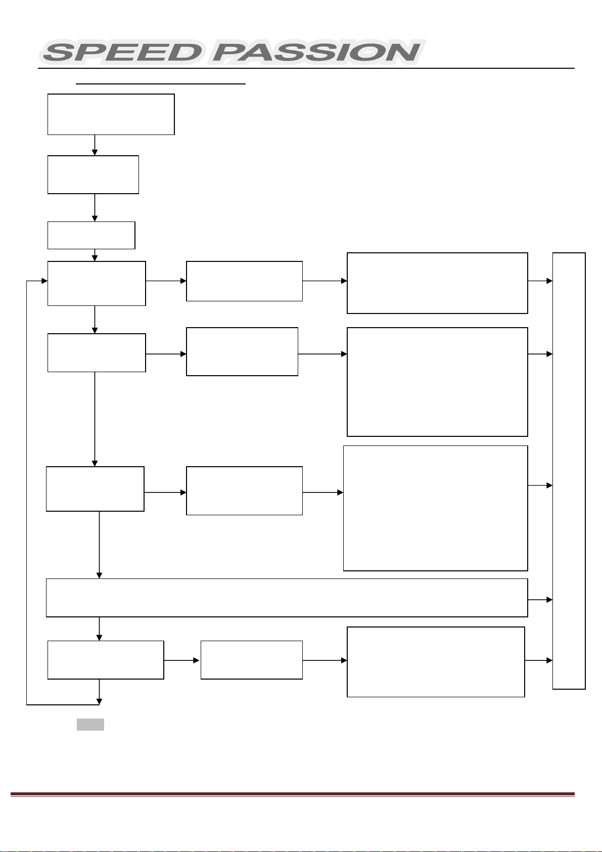
11.ProgramStockClubRaceESC
Note:
In the program process, the motor will emit “Beep” tones at the same time as the LED is flashes.
Ensure ESC is off. Turn on
the transmitter.
Orange LED flashes
for N times
Red LED flashes
Enter the corresponding
programmable item, the RED
LED flashes for several times,
the times present the current
value of this item
Press the SET key to choose the
programmable value , the RED LED
flashes for several times, the times
presents the serial number of the
value you are choosing
■The following steps are just like the above steps
Orange LED flashes
for 3 times
Orange LED flashes
for 2 times
Orange LED flashes
for 1 time
Hold the SET key,
Switch on the ESC
Red LED flashes 1 time, choose "Level 1"
Red LED flashes 2 times, choose "Level 2"
Red LED flashes 3 times, choose "Level 3"
Red LED flashes 4 times, choose " Level 4"
Red LED flashes 5 times, choose " Level 5"
Red LED flashes 6 times, choose " Level 6”
Red LED flashes 7 times, choose " Level 7"
Red LED flashes 8 times, choose " Level 8”
Red LED flashes 9 times, choose " Level 9”
Red LED flashes 1 time, choose "2.6V"
Red LED flashes 2 times, choose "2.8V"
Red LED flashes 3 times, choose "3.0V"
Red LED flashes 4 times, choose "3.2V"
Red LED flashes 5 times, choose "3.4V"
Red LED flashes 6 times, choose "None"
Enter the 1st item
"Running Mode"
Red LED flashes for 1 time to choose
"Forward with brake
" Red LED flashes for 2 times to choose
" Forward
/
Reverse with brake"
Enter the 3rd item
"DDRS3.0"
Enter the 2nd item
'”V/Cell Li Po Cut Off"
Press SET key to choose the value, the
flash times of RED LED means the
serial number of the value (1 time means
the 1st value, 2 times means the 2nd
value...)
Enter the Nth item
Release
SET key
Hold SET key for 3 seconds
Hold SET key for 3 seconds
Hold SET key for 3 seconds
Release
SET key
Press
SET key
Press
SET key
Press
SET key
Press
SET key
Release
SET key
Release
SET key
Finish Programming, switch off the ESC, and then switch it on

V1.1 Creation on Jan13th2012
King‐GoldenLimitedPage12
12.ProgrammableItemslist
12.1ProgrammableItemslistjustforReventon(Modifiedversion)
Attention:Theboldtextsinthebelowformarethedefaultsettings.
Programmable
Items
Programmable Value
1 2 3 4 5 6 7 8 9 10 11
Basic Item
1. Running
mode
Forward
with
brake
"No
reverse"
2. Threshold V /
Cell Li Po Cut
off
2.6V
/Cell
2.8V
/Cell
3.0V
/Cell
3.2V
/Cell
3.4V
/Cell
No
protect
ion
3. Dynamic
Multi Timing
System - DMTS
3.0
0° 3.75° 7.5° 11.25° 15° 18.75° 22.5°
26.5°
4. Digital
Racing
Response
System - DRRS
30
Level 1 Level
2 Level 3 Level 4 Level 5 Level 6 Level 7 Level 8 Level 9
Advanced Item
5. Percentage
Braking - ABS 0% 10% 20%
30% 40% 50% 60% 70% 80% 90% 100%
6. Percent Drag
Brake 0% 10%
20% 30% 40% 50% 60% 70% 80%
7. Throttle
Percent Reverse 20% 30% 40% 50% 60% 70% 80% 90% 100%
8. Neutral
Range 2% 4%
6% 8% 10% 12%
9. Over Heat
Protection
Enable
"95 °C
Cut off
"
Disab
le
Special Item
10.ESC
Temperature
11.Battery
Voltage
12. ESC
Firmware

V1.1 Creation on Jan13th2012
King‐GoldenLimitedPage13
12.2LimitedProgrammableItemslistjustforReventonSTOCKCLUBRACE
Note:Withoutfullunderstandingofaspecificfunctionanditsreason,itisnotrecommendedthatusers
makechangestothe“default”configuration.Defaultssettingshavebeenselectedasadirectresultof
testing.Usersareattheirownriskchangingconfigurations.
Programmabl
e Items Programmable Value
1 2 3 4 5 6 7 8 9 10 11
Basic Item
1. Running
mode
Forward
with
brake
"No
reverse"
2. Threshold V
/ Cell Li Po
Cut off
2.6V
/Cell
2.8V
/Cell
3.0V
/Cell
3.2V
/Cell
3.4V
/Cell
No
protec
tion
3. Digital
Racing
Response
System -
DRRS 3 0
Level 1 Leve
l 2
Level
3
Level
4
Level
5
Level
6
Level
7 Level
8
Level
9
Advanced Item
4. Percentage
Braking - ABS 0% 10% 20%
30% 40% 50% 60% 70% 80% 90% 100%
5. Percent
Drag Brake 0% 10%
20% 30% 40% 50% 60% 70% 80%
6. Neutral
Range 2% 4%
6% 8% 10% 12%
7. Over Heat
Protection
Enable
"95 °C
Cut
Disa
ble
Special Item
8. ESC
Temperature
9. Battery
Voltage
10. ESC
Firmware

V1.1 Creation on Jan13th2012
King‐GoldenLimitedPage14
12.3Install USB driver:
For Windows 7 / Vista
1. Open SpUsbDriver folder.
3. Press “Install” button to start.
4. USB driver will install automatically.
5. If security warning pops up, click on “Install this driver software anyway.”
6. Click ok to finish driver installation.
2. Double click SpUsbInstaller.exe to install

V1.1 Creation on Jan13th2012
King‐GoldenLimitedPage15
For Windows XP
1. Open SpUsbDriver folder.
2. Press “Install” button to start.
3. USB driver will install automatically.
4. Restart computer.
5. Connect PC and program card by USB cable.
6. Select “No, not this time”, then click “Next>” button.
7. Select “Install the software automatically (Recommended)”, then click “Next>” button.
.
2. Double click SpUsbInstaller.exe to install usb driver

V1.1 Creation on Jan13th2012
King‐GoldenLimitedPage16
8. Click “Continue Anyway”
9. Click “Finish” to finish the installation.
12.4Updating Program Card Firmware:
1. Install Speed Passion Reventon PC Interface on the PC.
2. Plug in the mini USB cable to the program card.
3. Pressing and hold the RESET button while plugging in the other end of the USB cable to the PC.
4. The program card will be display “- - - - “. Release the RESET button and launch the “Speed Passion Reventon PC
Interface” program.

V1.1 Creation on Jan13th2012
King‐GoldenLimitedPage17
5. Click the button – “UPDATE FIRMWARE”
6. Select “LED_Reventon_V1.0.pgd” and click OK.
7. Click “Yes” to start the update.
8. The process time is around 1 minute. The Speed Passion Reventon PC Interface program will show a process bar to display
the status of the update firmware.
9. When the firmware update is complete, a message box will pop up confirming completion. Close the Speed Passion
Reventon PC Interface program and unplug the USB cable from the program card to finish the update. If the pop up box
does not display “Download Success”, please repeat the process again from step 2. Ensure the selection of the firmware is
correct. Selecting the LCD firmware instead of LED to update the program card will cause the update to be unsuccessful.
This manual suits for next models
2
Table of contents
Other Speed Passion Engine manuals

Popular Engine manuals by other brands


Nicotra
Nicotra RLO Mounting instructions

Baumuller
Baumuller GNA 100 Commissioning Guide and Maintenance Instructions

Emerson
Emerson TITAN II Installation, operation and maintenance manual

FG Modellsport
FG Modellsport G230RC1 Instruction

BRP
BRP ROTAX FR 125 MAX Repair manual

Siemens
Siemens LOHER CHEMSTAR 1PS2 Operating instructions and installation