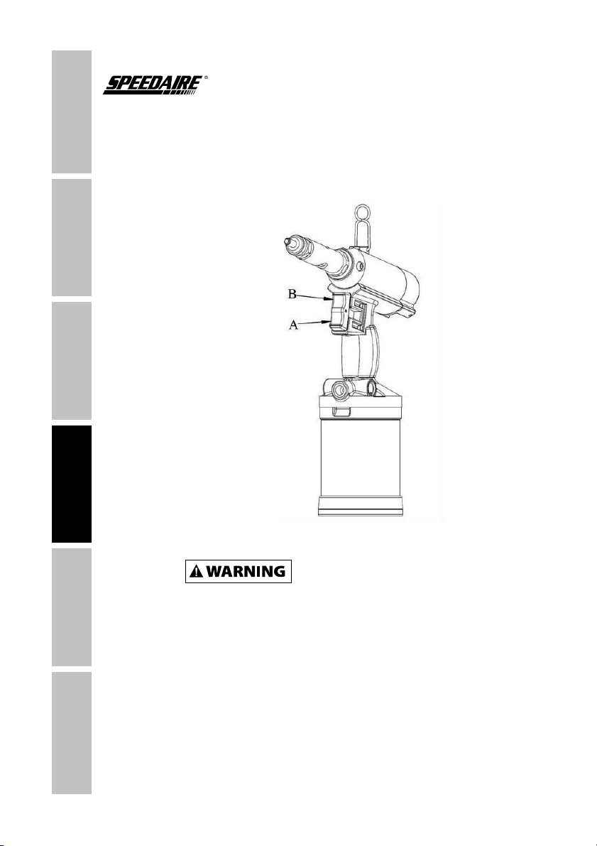
Speedaire 3CRH6B Instructions for use


EVASDNADAERESAELP
.SNOITCURTSNIESEHT
YLLUFERACDAER
BEFORE ATTEMPTING
TO ASSEMBLE, INSTALL,
EHTNIATNIAMROETAREPO
PRODUCT DESCRIBED.
PROTECT YOURSELF AND
OTHERS BY OBSERVING ALL
SAFETY INFORMATION. FAILURE
TO COMPLY WITH INSTRUCTIONS
COULD RESULT IN PERSONAL
INJURY AND/OR PROPERTY DAMAGE!
RETAIN INSTRUCTIONS FOR FUTURE
REFERENCE.
REVOCKCABOTREFERESAELP
GNIDRAGERNOITAMROFNIROF
REHTODNAYTNARRAWS’NOTYAD
IMPORTANT INFORMATION.
Model #: ___________________
Serial #: ___________________
Purch. Date: _______________
Printed in Taiwan
Version 0/ 4/ 2016
© 2015 W.W. Grainger, Inc.
All Rights Reserved
BEFORE YOU BEGIN
GETTING STARTED SAFETY /
SPECIFICATIONS
ASSEMBLY /
INSTALLATION OPERATION TROUBLESHOOTING MAINTENANCE /
REPAIR
See General Safety Instructions on page 2, and Cautions and Warnings
as shown.
1
Personal protection equipment
Unpack:
with the carrier
Contents:
UNPACKING

GENERAL SAFETY INFORMATION
GETTING STARTED
SAFETY /
SPECIFICATIONS
ASSEMBLY /
INSTALLATION
OPERATIONTROUBLESHOOTING
MAINTENANCE /
REPAIR
2
p
Some dust created by power sanding, sawing,
grinding, drilling, and other construction activities
contains chemicals known to cause cancer, birth defects or other
reproductive harm. Some examples of these chemicals are:
"
area, and work with approved safety equipment, such as those dust masks
that air specially designed to filter out microscopic particle.
SPECIFICATIONS
GETTING STARTED SAFETY /
SPECIFICATIONS
ASSEMBLY /
INSTALLATION OPERATION TROUBLESHOOTING MAINTENANCE /
REPAIR
3
Rivet Sizes or
Rivet Nut Sizes
1/4”
1/4”
5/32”
3/32”
Pulling Force (Ibs) 4000 5000 2100
Stroke
Maximum Air
Pressure (PSI)
Air Consumption per
Stroke (CFM)
Air Inlet (NPT) 1/4’’ 1/4’’ 1/4’’ 1/4’’
Recommended Hose
Size
Hydraulic oil
Overall Length 12” 12”
Overall Height 10”
Overall Width 5”
45RM38

GETTING STARTED
SAFETY /
SPECIFICATIONS
ASSEMBLY /
INSTALLATION
OPERATIONTROUBLESHOOTING
MAINTENANCE /
REPAIR
4
nfh
n
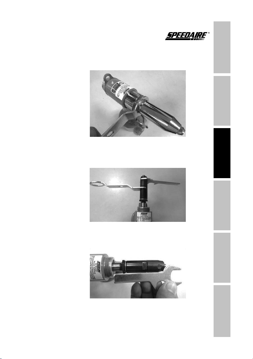
INSTALLATION INSTRUCTIONS
Figure 1
Figure 2
Inner Dia. of
Nosepiece
Outer Dia. of
Rivets Available
Nosepiece display
3/32”
GETTING STARTED SAFETY /
SPECIFICATIONS
ASSEMBLY /
INSTALLATION OPERATION TROUBLESHOOTING MAINTENANCE /
REPAIR
5
fhframe. Then
fjcrjc
jjpj
jp
jhs
g
corresponding,
previously loosened lock nut.
INSTALLATION INSTRUCTIONS
Figure 3
Figure 4
Figure 5

GETTING STARTED
SAFETY /
SPECIFICATIONS
ASSEMBLY /
INSTALLATION
OPERATIONTROUBLESHOOTING
MAINTENANCE /
REPAIR
INSTALLATION INSTRUCTIONS FOR 3CRH8B
supplied eye lever
bottom. Then
Figure 6
GETTING STARTED SAFETY /
SPECIFICATIONS
ASSEMBLY /
INSTALLATION OPERATION TROUBLESHOOTING MAINTENANCE /
REPAIR
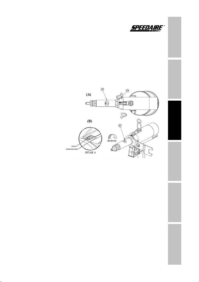
INSTALLATION INSTRUCTIONS FOR 3CRH8B
stroke. The
Adjust the nose piece following the sticker scale. Every turn
djusts the nose piece 1.5 mm.
Figure 7

GETTING STARTED
SAFETY /
SPECIFICATIONS
ASSEMBLY /
INSTALLATION
OPERATIONTROUBLESHOOTING
MAINTENANCE /
REPAIR
changing the nosepiece
I
Figure 8
Figure 9
OPERATING INSTRUCTIONS FOR 3CRH6B, 3CRH7B AND
45RM38

GETTING STARTED SAFETY /
SPECIFICATIONS
ASSEMBLY /
INSTALLATION OPERATION TROUBLESHOOTING MAINTENANCE /
REPAIR
using
i
press
the rivet rods
After the mandrel bottle adapter is emptied, plug the mandrel
bottle adapter into the spent mandrel bottle. Then follow the normal
operating procedure to continue using the tool.
OPERATING INSTRUCTIONS FOR 3CRH6B, 3CRH7B AND
45RM38
GETTING STARTED
SAFETY /
SPECIFICATIONS
ASSEMBLY /
INSTALLATION
OPERATIONTROUBLESHOOTING
MAINTENANCE /
REPAIR
Figure 11
OPERATING INSTRUCTIONS FOR 3CRH8B
ush the tie-rod straight against the fastener. The tie-rod will
automatically rotate into the fastener then stop.
s
Disconnect air from tool before all repairs! Stop
using the tool immediately if any of the following
$%
replacements must be done by a qualified person or an authorized service
center only.
10

GETTING STARTED SAFETY /
SPECIFICATIONS
ASSEMBLY /
INSTALLATION OPERATION TROUBLESHOOTING MAINTENANCE /
REPAIR
TROUBLESHOOTING
Symptom Possible Causes Corrective Action
j
safety cap
f
h
jh
Re-
chips can stick to the
nosepiece.
to clesr
malfunctioning
valve's
tv
cv
11

GETTING STARTED
SAFETY /
SPECIFICATIONS
ASSEMBLY /
INSTALLATION
OPERATIONTROUBLESHOOTING
MAINTENANCE /
REPAIR
TROUBLESHOOTING
Symptom Possible Causes Corrective Action
tv
would
av
b
oc
b
av
tb
s
o
cb
m
n
s
n
b
b
tr
n
b
tr
12

GETTING STARTED SAFETY /
SPECIFICATIONS
ASSEMBLY /
INSTALLATION OPERATION TROUBLESHOOTING MAINTENANCE /
REPAIR
TROUBLESHOOTING
13
spring/
spring
emptied when it is filled with
35 rivets' residues.

GETTING STARTED
SAFETY /
SPECIFICATIONS
ASSEMBLY /
INSTALLATION
OPERATIONTROUBLESHOOTING
MAINTENANCE /
REPAIR
MAINTENANCE
14
s
the rear jaw case and lock nut.
the front jaw case away from the frame.
be at the bottom of its stroke
removing
hand power
to the O-Rings.
into the
frame to the level of the top O-Ring.
for oil appearing in the air cylinder
R
Jaw Inspection and Replacement
Pneumatic Oil

GETTING STARTED SAFETY /
SPECIFICATIONS
ASSEMBLY /
INSTALLATION OPERATION TROUBLESHOOTING MAINTENANCE /
REPAIR
MAINTENANCE
15

GETTING STARTED
SAFETY /
SPECIFICATIONS
ASSEMBLY /
INSTALLATION
OPERATIONTROUBLESHOOTING
MAINTENANCE /
REPAIR
For Repair Parts, call 1-800-323-0620
24 hours a day – 365 days a year
Please provide following information:
0RGHOQXPEHU
6HULDOQXPEHULIDQ\
3DUWGHVFULSWLRQDQGQXPEHUDVVKRZQLQSDUWVOLVW
REPAIR PARTS ILLUSTRATION FOR 3CRH6B AND 3CRH7B
GETTING STARTED SAFETY /
SPECIFICATIONS
ASSEMBLY /
INSTALLATION OPERATION TROUBLESHOOTING MAINTENANCE /
REPAIR
Description Part No. Qty.
1 *** 1
2 *** 1
3 *** 1
4 *** 1
5 *** 1
*** 1
*** 1
1
1
*** 2
10 *** 1
11 *** 1
12 *** 1
13 *** 1
14 *** 1
15 *** 1
*** 2
*** 1
*** 1
*** 1
20 *** 1
21 *** 2
22 *** 3
23 *** 1
24 *** 1
25 *** 1
*** 1
*** 1
*** 1
*** 1
30 *** 1
31 *** 1
32 *** 1
33 *** 1
34 *** 1
35 *** 1
*** 1
1
REPAIR PARTS LIST FOR 3CRH6B AND 3CRH7B
GETTING STARTED
SAFETY /
SPECIFICATIONS
ASSEMBLY /
INSTALLATION
OPERATIONTROUBLESHOOTING
MAINTENANCE /
REPAIR
Description Part No. Qty.
1
1
1
*** 1
1
40 3
41 *** 1
1
42 *** 1
43 *** 1
*** 1
44 *** 1
45 *** 1
*** 1
*** 1
*** 1
50 *** 1
51 *** 1
53 *** 1
54 1
*** 1
1
1
1
*** 1
1
1
*** 1
*** 1
*** 1
*** 1
2
*** 5
1
1
REPAIR PARTS LIST FOR 3CRH6B AND 3CRH7B
This manual suits for next models
3
Table of contents
Languages:
Other Speedaire Rivet Tools manuals


