FAR KJ 73-A Setup guide

KJ 73-A
I
GB
- ISTRUZIONI ORIGINALI
RIVETTATRICE OLEOPNEUMATICA
PER INSERTI 6 - 32 ÷ 1/2" - 13 UNC
ISTRUZIONI D’USO - PARTI DI RICAMBIO
- TRANSLATION OF ORIGINAL INSTRUCTIONS
HYDROPNEUMATIC RIVETING TOOL
FOR INSERTS 6 - 32 ÷ 1/2" - 13 UNC
INSTRUCTIONS FOR USE - SPARE PARTS
KJ 73-A

KJ 73-A
Far S.r.l. - Massimo Generali
(Presidente del Consiglio di Amministrazione)
(Chairman of the Board of Directors)
(Président du Conseil d’Administration)
(Vorsitzender des Verwaltungsrates)
(Presidente del Consejo de Administración)
(Prezes Zarzadu)
(Председатель Административного Совета)
.............................................
La sottoscritta Far S.r.l., con sede in Quarto Inferiore (BO) alla via Giovanni XXIII n° 2,
DICHIARA
sotto la propria esclusiva responsabilità che la rivettatrice Modello KJ 73-A - Rivettatrice oleopneumatica Utilizzo: per inserti
filettati 6-32 ÷ 1/2"-13 UNC, numero di serie: vedi retro copertina, alla quale questa dichiarazione si riferisce è conforme ai
requisiti essenziali di sicurezza previsti dal D. Lgs. 17/2010 di recepimento della Direttiva Macchine 2006/42/CE e successive
modificazioni ed integrazioni,
e CU TR 010/2011.
La persona autorizzata a costituire il fascicolo tecnico risponde al nome di Massimo Generali, presso la Far S.r.l., con sede in
Quarto Inferiore (BO) alla via Giovanni XXIII n° 2.
The undersigned Far S.r.l., having its office in Quarto Inferiore (BO), Via Giovanni XXIII No. 2, herewith
DECLARES
on its sole responsability that the riveting machine Type KJ 73-A - Hydropneumatic tool Application: for threaded inserts
6-32 ÷ 1/2"-13 UNC, serial number: see back cover, which is the object of this declaration complies with the basic safety
requirements estabilished in the law decree Leg.D. 17/2010 of the Machinery Directive 2006/42/CE acknowledge and
subsequent amendments and integrations
and CU TR 010/2011
.
The person who is authorized to create the technical brochure is Massimo Generali, c/o Far S.r.l., head office in Quarto
Inferiore (BO), via Giovanni XXIII n. 2.
Quarto Inferiore, 04-11-2020
I
GB

I
I
ISTRUZIONI D’USO.................................................4
INSTRUCTIONS FOR USE.....................................13
PARTI DI RICAMBIO .............................................22
SPARE PARTS.......................................................24
KJ 73-A
GB
GB

IKJ 73-A
475036141 - KJ 73-A – rev 01 - ( 02-2021 )
AVVERTENZE E MISURE Dl SICUREZZA
ISTRUZIONI D’USO I
INDICE
GARANZIA ............................................................................4
AVVERTENZE E MISURE DI SICUREZZA...............................4
IDENTIFICAZIONE DELLA RIVETTATRICE .............................5
NOTE GENERALI E CAMPO DI APPLICAZIONE.....................5
PARTI PRINCIPALI................................................................5
DATI TECNICI........................................................................5
ALIMENTAZIONE DELL’ARIA.................................................6
OPERAZIONI PRELIMINARI..................................................6
POSA IN OPERA DELL’INSERTO...........................................7
ANOMALIE DI FUNZIONAMENTO..........................................8
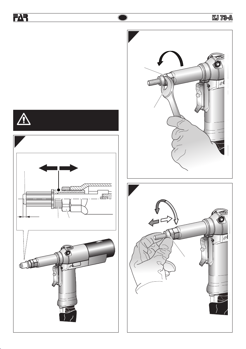
CAMBIO DI FORMATO ..........................................................8
REGOLAZIONE DEL GRUPPO TIRANTE TESTINA ...............10
RABBOCCO OLIO NEL CIRCUITO OLEODINAMICO.............11
MANUTENZIONE.................................................................12
SMALTIMENTO DELLA RIVETTATRICE ...............................12
ATTENZIONE!!!
La mancata osservanza o trascuratezza delle
seguenti avvertenze di sicurezza può avere
conseguenze sulla vostra o altrui incolumità e
sul buon funzionamento dell’utensile.
•Leggereattentamenteleistruzioniprimadell’uso.
•Perleoperazionidimanutenzionee/oriparazioneaffidarsi
a centri di assistenza autorizzati dalla FAR s.r.l. e fare uso
esclusivo di pezzi di ricambio originali. La FAR s.r.l. declina
ogni responsabilità per danni da particolari difettosi, che
si dovessero verificare per inadempienza di quanto sopra
(Direttiva CEE 85/374).
L’ELENCO DEI CENTRI DI ASSISTENZA È DISPONIBILE SUL
NS. SITO WEB: http://www.far.bo.it ( Organizzazione )
GARANZIA
Le rivettatrici FAR sono coperte da garanzia di 12 mesi.
Il periodo di garanzia dell'attrezzo decorre dal momento
della sua comprovata ricezione da parte dell'acquirente. La
garanzia copre l'utente/acquirente quando l'attrezzo viene
acquistato attraverso un rivenditoreautorizzato esolo quando
viene impiegato per gli usi per i quali è stato concepito. La
garanzia non è valida se l'attrezzo non viene utilizzato e se
non viene sottoposto a manutenzione come specificato nel
manuale di istruzione e manutenzione. In caso di difetti o
guasti la FAR S.r.l. si impegna unicamente a riparare e/o
sostituire, a propria discrezione esclusiva, i componenti
giudicati difettosi.
• Si raccomandal’usodell’utensiledapartedipersonale
specializzato.
• Durantel’impiegodell’utensile,usareocchialiovisiere
protettive e guanti.
• Pereseguireleoperazionidimanutenzionee/odiregolazione
dell’utensile utilizzare gli accessori in dotazione e/o le
attrezzature commerciali indicate nel capitolo Manutenzione.
• Perleoperazionidicaricaolio,usaresolofluidicon
caratteristiche indicate nel presente fascicolo.
• Incasodiperditeaccidentalidioliochedovesserovenire
a contatto con la pelle, lavarsi accuratamente con acqua e
sapone alcalino.
• L’utensilepuòesseretrasportatoamanoedèconsigliabile,
dopo l’uso, riporlo nel proprio imballo.
• Nonesistonoparticolariprescrizioniperlostoccaggio o
l'immagazzinamento.
• Si consigliaaifinidiuncorrettofunzionamentodella
rivettatrice, una revisione semestrale.
• Gliinterventidiriparazioneepuliziadell’utensiledovranno
essere eseguiti con macchina non alimentata dall’aria
compressa.
• È consigliabile,ovepossibile,I’usodiunbilanciatoredi
sicurezza.
• Incasodiesposizionequotidianapersonaleinambienteil
cui livello di pressione acustica dell’emissione ponderata
A sia superiore al limite di sicurezza di 70 dB (A), fare uso
di adeguati mezzi individuali di protezione dell’udito (cuffia
o tappo antirumore, diminuzione del tempo di esposizione
quotidiana etc...).
• Mantenereilbancoe/ol’areadilavoropulitaeordinata,il
disordine può causare danni alla persona.
• Nonlasciarechepersoneestraneeallavorotocchinogli
utensili.
• Assicurarsicheitubidialimentazionedell’ariacompressa
siano correttamente dimensionati per l’uso previsto.
• Nontrascinarel’utensilecollegatoall’alimentazionetirandolo
per il tubo; mantenere quest’ultimo lontano da fonti di calore
e da oggetti taglienti.
• Manteneregliutensiliinbuonostatod’usoepuliti,non
rimuovere mai le protezioni e il silenziatore dell’utensile.
•Dopoavereeseguitooperazionidiriparazionee/o
registrazione assicurarsi di avere rimosso le chiavi di servizio
o di registrazione.
•Primadiscollegareiltubodialimentazionedell’aria
compressa dalla rivettatrice, assicurarsi che quest’ultimo
non sia in pressione.
• Attenersiscrupolosamenteaquesteistruzioni.
• Nonutilizzarelarivettatriceinpresenzadievidentidanni.

5
I
KJ 73-A
75036141 - KJ 73-A – rev 01 - ( 02-2021 )
Ragione sociale e indirizzo
del fabbricante Designazione macchina
Numero di serie
KJ 73-A
KJ 73-A
KJ 73-A
430
205
130
296*
Ø 50
124*
Ø 28,5
ABC
I
EFG
D
L
M
N
*
con tirante per 3/8"-16 UNC
IDENTIFICAZIONE DELLA RIVETTATRICE
La rivettatrice KJ73-A è identificata da una marcatura
indicante ragione sociale e indirizzo, designazione della
macchina , marcatura CE. In caso di richiesta di assistenza
tecnica fare sempre riferimento ai dati riportati nella marcatura.
DATI TECNICI
• Pressionediesercizio ..........................................6 ÷ 7 BAR
• Diametrointernominimotuboalimentazione
aria compressa ............................................ø min. = 8 mm
• Consumomaxarialibera,perciclo...............................9 Nl
• Forzamassima......................................... 6 BAR - 31667 N
PESO:
•Pistola....................................................................1,480 Kg
•Totale..................................................................... 8,680 Kg
• Temperaturadiutilizzo...........................................-5°/+50°
• Valoremedioquadraticoponderatoin
frequenza dell’accelerazione complessiva (Ac)
a cui sono sottoposte gli arti superiori................ < 2,5 m/s2
• Pressioneacusticadell’emissioneponderata(A)).... 74 dBA
• Pressioneacusticaistantaneaponderata(C) ....... <130 dBC
• Potenzaacusticaponderata(A) ............................... 85 dBA
PARTI PRINCIPALI
A)....................................................................Tirante filettato
B).................................................................................Testina
C)....................................................Ghiera bloccaggio testina
D).........................................................Cannotto porta testina
E) .............................................................Attacco bilanciatore
F) ............................................................Tappo serbatoio olio
G).............................................................Motore pneumatico
I).........................................................Pulsante di svitamento
L) .......................................................... Pulsante di comando
M)............................................. Pomello di regolazione corsa
N)............................................ Allacciamento aria compressa
NOTE GENERALI E CAMPO DI APPLICAZIONE
L’uso dell’utensile è finalizzato esclusivamente all’utilizzo di
inserti filettati con filetto compreso tra 6-32 ÷ 1/2"-13 UNC.
Il sistema oleopneumatico utilizzato dalla rivettatrice KJ73-A
fornisce una maggior potenza rispetto al tradizionale sistema
pneumatico su cui si basano altri modelli di rivettatrici. Ciò
significa una drastica riduzione dei problemi dovuti all’usura dei
componenti con conseguente aumento di affidabilità e durata.
Le soluzioni tecniche adottate riducono le dimensioni e il peso
della macchina rendendo la rivettatrice KJ73-A assolutamente
maneggevole.Le possibilità di perdite dalsistema oleodinamico
sonoprecluse dall’impiego di guarnizioni a tenuta cheeliminano
questo problema.

IKJ 73-A
675036141 - KJ 73-A – rev 01 - ( 02-2021 )
f1
f3
B
A
M
15 0
GRUPPO FRL
ALIMENTAZIONE DELL’ARIA (fig. f1)
L’aria di alimentazione deve essere libera da corpi estranei e
da umidità per proteggere il dispositivo da usura precoce delle
parti in movimento; è consigliabile, pertanto, l’impiego di un
gruppo lubrificatore per aria compressa.
OPERAZIONI PRELIMINARI (fig. f2-f3)
Verificare che il gruppo, tirante filettato (A) e testina (B),
montatosulla rivettatrice, sia adeguatoallamisuradell’inserto
che si vuole serrare; in caso contrario procedere al cambio
di formato (pag. 6). Il gruppo tirante filettato (A) + testina
(B) montato sulla rivettatrice in confezione, corrisponde ad
una filettatura di 3/8"-16 UNC.
Prima diutilizzare la rivettatrice edopoogni cambio di formato
occorre regolare la corsa in funzione delle dimensioni, del
tipo di inserto e dello spessore del materiale da serrare.
Prima di compiere questa operazione ruotare il pomello (M)
secondo il senso della freccia, (+) per aumentare la corsa e (-)
per diminuirla. Considerando che all’aumentare della corsa
- rotazione del pomello (M) nel senso indicato dal simbolo
(+), la distanza “h” (pag. 7) diminuisce con conseguente
aumento dell’azione di serraggio.
NOTA: Prima della posa in opera definitiva dell’inserto è
bene verificare il serraggio che questo opera sugli spessori
interessati,compiendoulterioriregolazioni,comespecificato
a pagina 10 (le regolazioni riportate sono puramente
indicative; è consigliabile consultare i dati tecnici degli
inserti utilizzati).
ATTENZIONE!!! La regolazione non corretta
della corsa della rivettatrice può causare il
cattivo serraggio degli inserti e la probabile
rottura del tirante!
3 m Max

7
I
KJ 73-A
75036141 - KJ 73-A – rev 01 - ( 02-2021 )
f4
f5
f6
POSA IN OPERA DELL’INSERTO (fig. f4-f5-f6)
Verificare che il gruppo tirante filettato (A) e testina (B)
montato sulla rivettatrice sia adeguato alla misura dell’inserto
che si vuole utilizzare.
Regolare la corsa come riportato (fig. f3). Inserire l’inserto
sul tirante (A) ed esercitare su di esso una leggera pressione
come indicato in figura f4, in questo modo l’inserto si avvita
automaticamente sul tirante filettato.
Assicurarsi che la testa dell’inserto vada in battuta con la
testina (B) verificando che il tirante (A) fuoriesca di 2 mm
dall’inserto. In caso di ulteriore regolazione del tirante (A)
procedere come riportato a pag. 10.
E' possibile ora procedere alla messa in posa dell' inserto,
premendo il pulsante (D) (fig.f5 - f7) fino alla tirata completa
dell' inserto, per il disimpegno del tirante premere il pulsante
(P) (fig.f7).
Per una corretta posa ed un corretto funzionamento
della macchina è necessario che gli inserti utilizzati siano
adeguatamente puliti.
Nota: Se necessario, in funzione del serraggio desiderato,
compiere ulteriori regolazioni della corsa della rivettatrice,
mediante la rotazione del pomello (M) (fig. f3-f6).
Deformazione insufciente = l’inserto potrebbe ruotare
all’interno dell’alloggiamento pregiudicandone l’utilizzo e
la resistenza.
Deformazione eccessiva = possibili danneggiamenti
dell’inserto e tirante (A) con probabili rotture di entrambi
i componenti.
B
A
D
M
2 mm

IKJ 73-A
875036141 - KJ 73-A – rev 01 - ( 02-2021 )
P
P
D
ANOMALIE DI FUNZIONAMENTO (fig. f7)
In tutti i casi in cui si verificano condizioni per le quali sia necessario ottenere uno svitamento forzato del tirante filettato
dall'inserto, premere il pulsante (P).
ATTENZIONE!Eseguire questa operazione trattenendo saldamente la rivettatrice in modo da impedirle
eventuali bruschi movimenti che potrebbero danneggiare persone o cose.
f7
CAMBIO DI FORMATO (fig. f9 f10-f11)
Per effettuare il cambio di formato procedere come segue:
•Togliere l’alimentazione dell’aria compressa dalla rivettatrice.
•Svitare il cannotto porta testina (O) con una chiave commerciale di mm 22 (f9).
•Togliere il tirante filettato, spingendolo e contemporaneamente sollevandolo (f10).
•Dopo aver preparato il tirante filettato (A) della misura desiderata, disporre e sostenere i componenti come in f11 ed
eseguire il montaggio, assicurandosi che i particolari siano correttamente in sede, facendo ruotare a mano il tirante
(f11).
ATTENZIONE!
Le operazioni sopraelencate devono essere eseguite con macchina non alimentata.

9
I
KJ 73-A
75036141 - KJ 73-A – rev 01 - ( 02-2021 )
22 mm
O
f9 f11
f10
ATTENZIONE!
•Nel componente (R) il lato da inserire nella testa tirante
è calamitato per evitarne la caduta accidentale nelle
operazioni di cambio formato.
•Avvitare il cannotto porta testina (O) con una chiave
commerciale di mm 22 e serrare correttamente.
ATTENZIONE!
Le operazioni sopraelencate devono essere
eseguite con macchina non alimentata.

IKJ 73-A
10 75036141 - KJ 73-A – rev 01 - ( 02-2021 )
f13
f14
f12
22 mm
C
B
ATTENZIONE!
Le operazioni sopraelencate devono essere
eseguite con macchina non alimentata.
REGOLAZIONE DEL GRUPPO TIRANTE TESTINA
(fig. f12-f13-f14)
Al variare della lunghezza dell’inserto da serrare occorre
regolare la posizione della testina (B) rispetto al tirante
filettato (A).
Togliere l’alimentazione dell’aria compressa dalla rivettatrice.
Avvitare manualmente un inserto della lunghezza desiderata
sul tirante filettato fino a che la testa dell’inserto vada in
battuta con la testina (B) della rivettatrice. La testina (B) è
regolata correttamente se il tirante filettato fuoriesce per
circa 2 mm dall’inserto avvitato su di esso. In caso contrario
sbloccare la ghiera (C) mediante una chiave commerciale di
mm 22 quindi avvitare o svitare la testina (B) fino a trovare
la giusta posizione, al termine bloccare la ghiera (C).
A
BC
2 mm

11
I
KJ 73-A
75036141 - KJ 73-A – rev 01 - ( 02-2021 )
f15
19 mm
H
I
M
KJ 73-A
ATTENZIONE!
Non schiacciare o tagliare i tubi che collegano la rivettatrice al booster.
Si raccomanda l’uso di olio HLP 32 cSt o simili.
RABBOCCO OLIO NEL CIRCUITO OLEODINAMICO
(fig. f15)
Verificare periodicamente (15000 cicli) che il livello dell’olio non scenda mai al di sotto dei 3/4 indicati dall’apposito segnalatore (I).
Nel caso si rendesse necessario, immettere olio idraulico HLP 32 CST.
ATTENZIONE ! Nel caso questa operazione non venga effettuata, si potrà riscontrare nel tempo, un calo di corsa della rivettatrice, che andrà
accentuandosi fino a comprometterne il funzionamento. Occorrerà pertanto eliminare la presenza d’aria all’interno del circuito oleodinamico e
ripristinarne la corretta quantità di olio.
Procedere quindi come segue: con macchina non alimentata ruotare il pomello (M) verso il segno “+” sino al finecorsa, togliere il tappo (H)
servendosi di una chiave di mm 19.
Con macchina alimentata rabboccare con olio, eseguire alcuni cicli di rivettatura rabboccando olio, mantenendo l’impugnatura bassa rispetto
al Booster come da figura (f15). Ripetere l’operazione fino al raggiungimento della corsa come da figura (f16).
Il rabbocco si considera completato quando il livello dell’olio si stabilizza con il bordo del foro filettato. Rimontare quindi il tappo (H).
Èestremamenteimportanteattenersialleistruzionisopraindicateedeffettuareleoperazionidirabboccooliomunitidiguanti.L’oliofuoriuscito
durante le operazioni indicate, dovrà essere raccolto in appositi recipienti ed affidato successivamente ad una ditta autorizzata per lo smaltimento
del rifiuto.

IKJ 73-A
12 75036141 - KJ 73-A – rev 01 - ( 02-2021 )
MANUTENZIONE
Manutenzione giornaliera
- Controllare che il tirante filettato non sia danneggiato.
- Controllare il sistema di alimentazione dell’aria compressa.
- Controllare che la corsa dell’attrezzo sia adatta per inserire l’inserto selezionato (vedere le istruzioni relative alla regolazione
della corsa, riportate a pagina 6).
- Controllare che non vi siano perdite di aria o di olio. In tal caso sostituire eventuali raccordi o guarnizioni danneggiate.
- Controllarechelapressionedialimentazionedell’ariacompressasiadimax 7 bar.
Manutenzione settimanale
- Controllare il livello dell’olio verificando che la corsa della rivettatrice soddisfi i requisiti minimi di 10 mm senza inserto
applicato (fig. f16). Se la verifica non soddisfa i requisiti minimi ripetere la procedura di rabbocco olio (fig. f15).
Revisione della rivettatrice
Èconsigliabileprocedereadunarevisionecompletadellarivettatricedopo600.000 cicli oppure ogni anno.
In questo caso rivolgersi esclusivamente a centri autorizzati dalla FAR S.r.l.
SMALTIMENTO DELLA RIVETTATRICE
Per lo smaltimento della rivettatrice attenersi alle prescrizioni imposte dalle leggi nazionali.
Dopo aver scollegato la macchina dall’impianto pneumatico, procedere allo smontaggio dei vari componenti
suddividendoli in funzione della loro tipologia: acciaio, alluminio, materiale plastico, ecc.
Procedere quindi alla rottamazione nel rispetto delle leggi vigenti.
f16
10mm(+0.2 )
0

13
GB
KJ 73-A
75036141 - KJ 73-A – rev 01 - ( 02-2021 )
INSTRUCTIONS FOR USE I
INDEX
GUARANTEE .......................................................................13
SAFETY MEASURES AND REQUIREMENTS .......................13
TOOL IDENTIFICATION .......................................................14
GENERAL NOTES AND USE ................................................14
MAIN COMPONENTS ..........................................................14
TECHNICAL DATA ...............................................................14
AIR FEED.............................................................................15
PRELIMINARY OPERATIONS..............................................15
PLACING OF THE INSERT...................................................16
WORKING PROBLEMS .......................................................17
CHANGE OF SIZE ............................................................... 17
ADJUSTMENT OF TIE-ROD/HEAD UNIT............................. 19
TOOPING UP THE OIL-DYNAMIC CIRCUIT .........................20
MAINTENANCE .................................................................. 21
DISPOSAL OF THE RIVETING TOOL ...................................21
CAUTION!!!
All the operations must be done in conformity
with the safety requirements, in order to avoid
any consequence for your and other people
security and to allow the best tool work way.
•Readtheinstructionscarefullybeforeusingthetool.
• Forallmaintenanceand/orrepairspleasecontact
FAR s.r.l. authorized service centers and use only
original spare parts. FAR s.r.l. may not be held liable
for damages from defective parts caused by failure
to observe what mentioned above (EEC directive
85/374).
THE LIST OF THE SERVICE CENTRES IS AVAILABLE ON
OUR WEBSITE
http://www.far.bo.it ( Organization )
•Thetoolmustbeusedonlybyexpertworkers.
GUARANTEE
FAR riveting tools are covered by a 12-month warranty. The
tool warranty period starts on the date of delivery to the
buyer, as specified in the relevant document. The warranty
covers the user/buyer provided that the tool is purchased
through an authorized dealer and only if it is used for the
purposes for which it was conceived. The warranty shall
not be valid if the tool is not used or maintained as specified
in the instruction and maintenance handbook. In the event
of defects or failures, FAR S.r.l. shall undertake solely to
repair and/or replace the components it judges to be faulty.
• Aprotectivevisorandglovesmustbeputonwhenusingthe
tool.
• Useequipmentrecommendedinthemaintenancechapterto
do any maintenance and/or regulation of the tool.
• Fortoppinguptheoil,wesuggestusingonlyfluidsin
accordance with the features specified in this working book.
• Ifanydropofoiltouchesyourskin,youmustwashwith
water and alkaline soap.
• Thetoolcanbecarriedandwesuggestputtingitintoitsbox
after using.
• Thetoolneedsathoroughsix-monthlyoverhaul.
• Therearenospecialrequirementsforstorage.
• Repairingandcleaningoperationsmustbedonewhenthe
tool is not fed.
• Asafetybalancerissuggestedwhenitispossible.
• IftheA-weightedemissionsoundpressurelevelismorethan
70 dB (A), you must use some hearing protections (anti-noise
headset, etc.).
• Theworkbenchandtheworksurfacemustbealwaysclean
and tidy. The untidy can cause damages to people.
• Donotallowunauthorizedpersonstousetheworkingtools.
• Makeyousurethatthecompressedairfeedinghoseshave
the correct size to be used.
• Donotcarrytheconnectedtoolbypullingthehose.Thehole
must be far from any heating sources or from cutting parts.
• Keepthetoolsingoodconditions;donotremoveeithersafety
parts or silencers.
• Afterrepairingand/oradjusting,makesureyouhavealready
removed the adjusting spanners.
• Beforedisconnectingthecompressedairhosefromthetool
make sure that there is no pressure in the hose.
• Theseinstructionsmustbecarefullyfollowed.
• Donotusetherivetingtoolinthecaseofvisibledamage.
SAFETY MEASURES AND REQUIREMENTS

GB
14
KJ 73-A
75036141 - KJ 73-A – rev 01 - ( 02-2021 )
Company name and
address Designation of the tool
Serial number
KJ 73-A
KJ 73-A
KJ 73-A
17”
8”
5”
11,6”*
Ø 1,97”
4,8”*
Ø 1,12”
ABC
I
EFG
D
L
M
N
TOOL IDENTIFICATION
The riveting tool KJ73-A is identified from a marking
that shows company name and address of manufacturer,
designation of the tool, CE. Always refer to the information on
the riveting tool when requesting technical service.
TECHNICAL DATA
• Workingpressure ........................................ 87 ÷ 101.5 psi
• Min.int.diam.ofthecompressedairfeedinghose .0.315 "
• Maxfreeairconsumptionpercycle......................5.492 in³
• Maximumforce........................................87 psi - 7.119 lbf
WEIGHT:
•Gun............................................................................. 3.3 lb
• Weight ..................................................................... 19.1 lb
• Workingtemperature.................................... -23°F/+122°F
• Rootmeansquareintotalaccelerationfrequency(Ac)to
which the arms are subjected .......................... < 98.42 ips²
• A-weightedemissionsoundpressurelevel.............. 74 dBA
• PeakC-weightedinstantaneoussoundpressure . <130 dBC
• A-weightedsoundpower........................................ 85 dBA
MAIN COMPONENTS
A)..................................................................Threaded tie rod
B)....................................................................................Head
C)......................................................Ring-nut clamping head
D)..............................................................Tube carrying head
E) ............................................................Balancer connection
F) ........................................................................Oil tank plug
G)................................................................ Pneumatic motor
I)...............................................................Unscrewing button
L) ............................................................Control push-button
M)........................................................Stroke-adjusting knob
N)................................................ Compressed air connection
*with
3/8"-16 UNC
tie rod
GENERAL NOTES AND USE
The tool can be employed only for threaded inserts 6-32 ÷
÷ 1/2"-13 UNC diameter.
The KJ73-A hydropneumatic system assures more power
than the pneumatic system used for other models.
That means a reduction in the problems due to the wear and
tear of the components, therefore, there will be an increase
in reliability. The technical solutions adopted reduce the
dimensions and the weight of the tool, which is very handy
for these reasons.
The possibilities of leakage from the oil-dynamic system, are
eliminated by some sealed gaskets, which solve this problem.

15
GB
KJ 73-A
75036141 - KJ 73-A – rev 01 - ( 02-2021 )
f1
f3
B
A
M
15 0
FRL UNIT ATTENTION! The incorrect adjustment of the
riveting tool can cause a bad clamping of the
inserts and a possible break of the tie rod!
PRELIMINARY OPERATIONS (fig. f2-f3)
Check that the threaded tie rod (A) and head (B) couple
assembled on the riveting tool is suitable to the size of the
insert to clamp; otherwise change the size (page 34). The
tie-rod (A)/head (B) unit assembled on this riveting tool,
corresponds to a 3/8"-16 UNC thread.
Before using the riveting tool and after each change of size, the
stroke should be adjusted according to the dimensions, type
of the insert and thickness of the material to clamp. Before
carrying out this operation rotate the knob (M) according to
the direction of the arrow, (+) for increasing the stroke and (-)
for decreasing it. Increasing the stroke - rotation of knob (M)
- in the direction indicated with the symbol (+), the distance
“h” (page 28) decreases increasing the clamping action.
NOTE: Before the definitive placing of the insert, its clamping
on the thicknesses involved should be checked, carrying
out other adjustments, as shown at page 39 (the specified
adjustments are just an indication, it is advisable to see the
technical data of the inserts used).
AIR FEED (fig. f1)
The air feed must be free from foreign bodies and humidity in
order to protect the device from premature wear and tear of
the components in movement, therefore we suggest to use a
lubricator group for compressed air.
118" Max

GB
16
KJ 73-A
75036141 - KJ 73-A – rev 01 - ( 02-2021 )
f4
f5
f6
PLACING OF THE INSERT (fig. f4-f5-f6)
Check that the threaded tie rod (A) and head (B) couple
assembled on the riveting tool is suitable to the size of the
insert to be used.
Adjust the stroke as indicated (fig. f3).
Introduce the insert on the tie rod (A) and push slightly on it
as indicated in figure f4, so as to make it clamp automatically
on the threaded tie rod. Make sure that the insert head
touches the head (B) checking that the tie rod (A) comes
out of 0.078" from the insert.
In case of further adjustments of the tie rod (A) follow the
instructions of page 19.
It is now possible to place the insert pushing the button (D)
(fig.f5-f7) until the insert is completely pulled, and push
the button (P) to release the tie rod (fig.f7).
For a correct placing and right working of the machine, the
inserts to be used should be properly cleaned.
Note: According to the desired clamping, carry out other
adjustments of the riveting tool stroke, rotating the knob
(M) (fig. f3-f6), if necessary.
Insufcient deformation = the insert could rotate inside the
housing compromising its use and resistance.
Excessive deformation = possible damages of the insert
and tie rod (A) with eventual breaks of both components.
BA
D
M
0.078"

17
GB
KJ 73-A
75036141 - KJ 73-A – rev 01 - ( 02-2021 )
P
P
D
WORKING PROBLEMS (fig. f7)
Any time it is necessary to unscrew forcedly the threaded tie rod from the insert, push the button (P).
ATTENTION!Carry out this operation keeping the riveting tool firmly in order to avoid sharp movements
which could damage people or things.
f7
CHANGE OF SIZE (fig. f9-f10-f11)
To change the size make as follows:
•Disconnect the compressed air feeding from the tool.
•Unscrew the cone-carrying head (O) by a 22 mm standard spanner (f9).
• Extractthethreadedtie-rod,pushingandliftingitatthesametime(f10).
•After preparing the threaded tie-rod (A) of the size you need, arrange and keep the components as shown in f11 and
assemble. Be sure that the components are correctly placed, rotating the tie-rod by hand (f11).
ATTENTION!
Disconnect the machine before carrying out the above-mentioned operations.

GB
18
KJ 73-A
75036141 - KJ 73-A – rev 01 - ( 02-2021 )
f9 f11
f10
22 mm
O
ATTENTION!
•The side of the component (R) to be entered in the head
of the tie-rod is provided of a magnet to avoid accidental
fall during the operations of change of size.
•Screw the cone carrying heads (O) by a 22 mm standard
spanner and clamp correctly.
ATTENTION!
Disconnect the machine before carrying out
the above-mentioned operations.

19
GB
KJ 73-A
75036141 - KJ 73-A – rev 01 - ( 02-2021 )
f13
f14
f12
22 mm
C
B
ATTENTION!
Disconnect the machine before carrying out the
above-mentioned operations.
ADJUSTMENT OF TIE-ROD/HEAD UNIT (fig. f12-f13-f14)
Changing the length of the insert to clamp, the position of
the head (B) compared to the threaded tie rod (A) should
be adjusted.
Disconnect the compressed air feeding from the tool.
Screw an insert of the desired length on the threaded tie
rod manually until the insert head touches the riveting tool
head (B). The head is adjusted correctly if the threaded tie
rod comes out of the insert screwed on it of about 0.078".
Otherwise unblock the ring nut (C) with a 22 mm standard
spanner then screw or unscrew the head (B) up to the right
position, and block the ring nut (C).
A
BC
0.078"

GB
20
KJ 73-A
75036141 - KJ 73-A – rev 01 - ( 02-2021 )
f15
19 mm
H
I
M
KJ 73-A
ATTENTION! Do not crush or cut the pipes that connect the riveter to the booster.
We recommend to use oil HLP 32 cSt or similars.
TOPPING UP THE OIL-DYNAMIC CIRCUIT (fig. f15)
Periodically check (15,000 cycles) that the oil level never falls below the 3/4 reported by the appropriate indicator (I).
If necessary, add HLP 32 CST hydraulic oil.
WARNING ! If this operation is not carried out, it will be possible to notice over time a drop in the riveting tool stroke, which
will increase until it compromises its functioning. Therefore, it will be necessary to eliminate the air inside the hydraulic
circuit and restore the correct amount of oil. Then proceed as follows: with machine with air supply off, turn the knob (M)
as much as possible towards the "+" sign, remove the cap (H) with a 19 mm wrench. With the air supply on, top up with oil,
perform a few riveting cycles adding oil while keeping the handle down with respect to the Booster, as shown in the picture 15.
Repeat the operation until reaching the stroke as shown in the picture 16.
Topping up is completed when the oil level is stable and touches the lip of the threaded hole. Fit again the cap (H).
Itisextremelyimportanttofollowtheinstructionsaboveandcarryouttheoilrefillingoperationswithgloves.Theoilspilled
during the indicated operations must be collected in special containers and subsequently entrusted to an authorized company
for the disposal of the waste.
Table of contents
Languages:
Other FAR Rivet Tools manuals