TKR Group VAS 6790/1 User manual

VAS 6790
VAS 6790/1
VAS 6791
BA2
Translation of the original instructions
Pneumatic/hydraulic
blind riveting tool
Setup – Installation: Rivet clamp
ATTENTION
This supplementary sheet serves as a supplement to the instruction manual BA1
(VAS 6790/2, VAS 6792, VAS 6792/1, VAS 6792/2) and may only be used in
conjunction with it.
Additional information to the instruction manual
BA1 (VAS 6790/2, VAS 6792, VAS 6792/1, VAS 6792/2)

2
VAS 611 007
ElektronischesMesssystem
zurNockenwelleneinstellung
Betriebsanleitung
Originalbetriebsanleitung
?
www.tkr-support.comOwner‘s manual
Owner‘s manual
digital
USB-Stick
1. Download current
owner‘s manuals
2. Support

3
Chapter Page
Safety
1.1 Designations 4
Technical data
2.1 Scope of supply, rivet clamp set 5
2.2 Technical Specications 5
2.3 Technical Data Rivet Clamp 6
2.4 Technical data, screw needles 8
2.5 Overview of rivet inserts 9
Application
3.1 Connecting the rivet clamp to the pressure generator 11
3.2 Inserting the riveting tool 12
3.3 Areas of application 16
3.4 Checking Riveting Results 21
3.5 Cleaning the Riveting Tools 22
3.6 Ending the operation 23
1.
2.
3.
This instruction manual is protected by copyright. No use is permitted outside the strict limit-
ations of copyright legislation without the consent of the manufacturer. Unauthorized use will
make the oender liable to criminal prosecution. This also applies to the extraction of individual
illustrations and the use of text in the extract form.

4
A B C D E G H
F
1.1.1
1.1 Designations
Marking on the rivet clamp
A Symbol to read the instruction manual
B Symbol to wear protective gloves
C Symbol to wear protective goggles
D Manufacturer‘s identication
E Type designation
F Serial number, production date
G Warning that ngers could become trapped
H Warning that hands could become trapped
For safe handling, it is essential that you observe the safety and application
instructions in the original VAS 6790/ VAS 6791 instruction manual.
Information regarding this manual

5
2.1.1
2.1 Scope of supply, rivet clamp set
2.2 Technical Specifications
VAS 6790/1
1x Rivet clamp NB-230-140
1 unit extension
Environmental
temperature 5–50 °C / 41–122 °F
Prescribed safety
clothing
Protective gloves, face mask
(refer also to BGR 192)

6
112
58
110
40
45
NB-45-40
VAS 6790/57
348
140
230
364
110
18
NB-230-140
VAS 6790/58
2.3.1
2.3.2
2.3 Technical Data Rivet Clamp

7
1Not included in basic kit VAS 6791
Title NB-45-40 NB-230-1401
Art. No. VAS 6790/57 VAS 6790/58
Length 112 mm 348 mm
Width 58 mm 58 mm
Height 110 mm 364 mm
Clamp aperture 40 mm 140 mm
Aperture depth 45 mm 230 mm
Weight 1.4 kg 9.2 kg
Extension – 110 mm x Ø 18 mm

8
Ø 2,4 mm Ø 4,0 mm Ø 4,8 mm
2.4.1
2.4 Technical data, screw needles
Title Screw needles
Art. No. VAS 6790/53 VAS 6790/52 VAS 6790/51
Ø 2.4 mm 4.0 mm 4.8 mm
Color brown yellow green

9
VAS 6790/24 VAS 6790/25 VAS 6790/26
D1
D4 D5 D6
D7 D8 D9
D2 D3
VAS 6790/27 VAS 6790/28 VAS 6790/29
VAS 6790/30 VAS 6790/31
VAS 6790/33
VAS 6790/36 VAS 6790/37
VAS 6790/35
VAS 6790/38
VAS 6790/32
D10 D11 D12
D14D13
2.5 Overview of rivet inserts

10
D15 D16 D17
S1
S4
S7 S8
Ø 5 mm
S5 S6
Ø 5 mm
S2
Ø 3 mm
S3
Ø 3 mm
VAS 6790/37 VAS 6790/38 VAS 6790/39
VAS 6790/42VAS 6790/41VAS 6790/40
VAS 6790/43 VAS 6790/44 VAS 6790/45
VAS 6790/47VAS 6790/46
2.5 Overview of rivet inserts

11
3.1.1 3.1.2
3.1.3 3.1.4
3.1.5 3.1.6
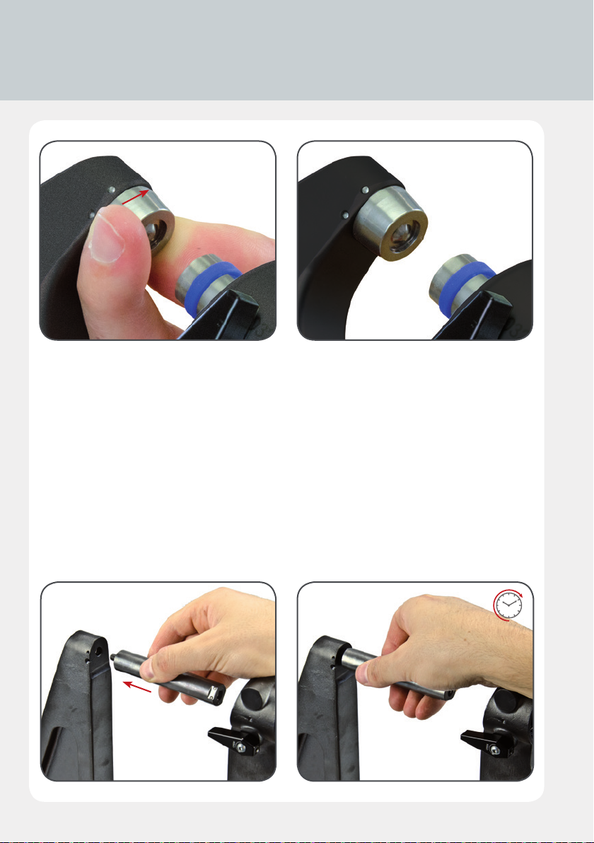
3.1 Connecting the rivet clamp to the
pressure generator

12
The threads on the hydraulic cylinder and the Booster must be clean and un-
damaged! The securing device must be fully engaged in position. The rivet
inserts must be clean and undamaged!
3.2 Inserting the riveting tool
3.1 Connecting the rivet clamp to the pressure
generator
Two rivet clamps are currently available for use with the riveting tool kit:
1Not included in basic kit VAS 6791
3.1.1 – 3.1.6
Place the riveting clamp on the Compact Booster cylinder. The arrows and dots must be
aligned (position: open). Then turn the rivet clamp to the next marking (position: close) and
lock in position with the lever.
Rivet clamp Art. No. Clamp aperture
NB-45-40 VAS 6790/57 up to 40 mm
NB-230-1401VAS 6790/58 up to 140 mm

13
3.2.1 3.2.2
3.2.3 3.2.4
3.2.5 3.2.6
14
3.2.7 3.2.8
3.2.9 3.2.10
3.2.1 – 3.2.8
Insert the rivet insert required for the work process into the rivet clamp recess, as required, or
insert the plunger rod and secure with 1/4-turn. Do not use force.
Select the corresponding counter-piece, locating and locking it in position in the opposite side
of the rivet clamp in the same way. Do not use force.
3.2 Inserting the riveting tool

15
3.2.11 3.2.12
7
3.2.13
3.2.9 – 3.2.12
When using a large rivet clamp with a clamp aperture of up to 140 mm, the extension VAS
6790/59 must also be tted. This is screwed either into the seating on the rivet clamp or into
the plunger rod and hand-tightened. Do not use force. The rivet insert can now be placed in
the extension seating (see rivet clamp up to 40 mm). Check that the extension is rmly seated
before and after each riveting operation.
3.3
Each time rivet inserts are to be tted, the bolt and die must be checked for a
correct match rst!
Refer to the areas of application on the following page for this.
3.2.13
Check that the riveting heads, and if
necessary the extension, are rmly seated
after each riveting operation. Rivet inserts
that have come loose present a hazard for
the operator and can lead to damage to
the equipment.

16
D4
D5
D3
D5
3.3.1 3.3.2
S7
S6
S8
S6
S4
D5
S5
D5
3.3.3 3.3.4
3.3.5 3.3.6
3.3 Areas of application

17
D5
D12
D7
D6
3.3.7 3.3.8
Rivet Procedure Tool pair
Punch rivet
5.3x5.5 mm
5.3x6.5 mm
Pressing out from two-ply sheet connections D31+ D5
Pressing out from 3-ply sheet connections or other thi-
cker connections D41+ D5
Setting 5.3x5.5 mm punch rivets S6 + S7
Setting 5.3x6.5 mm punch rivets S6 + S8
Pressing out from punch-rivet connections from 2-ply
sheet connections S4 + D5
Pressing out from punch-rivet connections from 2-ply
sheet connections S52+ D5
Rivet Procedure Tool pair
Pop rivet
Ø 4.8 mm
Hole punching and stamping D6 + D7
Ø 8 mm hole punching for hole-spot welding4D5 + D12
4Pre-drill out both sheets to Ø 2.5 mm and place a 2.4 mm xing clamp in every sixth hole. Separate the drilled sheets
and punch each hole separately.
1If punch rivets are used at a later date, no use may be made of rivet inserts D1, D3 and D4. This means that it is not
possible to center the new punch rivets.
2Position the die for the setting procedure in the deformation which has been created by pushing out through the
metal sheet on the die side.

18
D1
D2
D3
D2
S3
S2
S1
D2
3.3.9 3.3.10
3.3.11 3.3.12
3.3 Areas of application
Rivet Procedure Tool pair
Stanzniet
Ø 3,2 mm
Ø 3,5 mm
Pressing out from two-ply sheet connections D11+ D2
Pressing out from 3-ply sheet connections or other thicker
connections D2 + D31
Setting 3.2 mm punch rivets S2 + S3
Pressing out from punch-rivet connections from 2-ply
sheet connections S12+ D2
1If punch rivets are used at a later date, no use may be made of rivet inserts D1, D3 and D4. This means that it is not
possible to center the new punch rivets.
2Position the die for the setting procedure in the deformation which has been created by pushing out through the
metal sheet on the die side.

19
D10
D11
D10
D11
17
3.3.13 3.3.14
D8
D8
D9
D8
3.3.15 3.3.16
13
Rivet Procedure Tool pair
Full rivet
Ø 4.0 mm
Perforating and stamping (with drill hole) D10 + D11
Perforating and stamping (without drill hole) D10 + D113
Reshaping the areas of the connection deformed while
pressing out. D8 + D8
Pressing in D8 + D9
3For this application, remove the bolt from the D11 insert with an SW 13 open-ended spanner (upper part) and an SW
17 open-ended spanner (lower part)

20
D13
D14
D17
D17
D16
D15
D17
D17
3.3.17 3.3.18
3.3.19 3.3.20
3.3 Areas of application
Rivet Procedure Tool pair
Full rivet
Ø 6.0 mm
Pressing out from 3-ply sheet connections or other thi-
cker connections D13 + D14
Hole punching and stamping D15 + D16
Reshaping the areas of the connection deformed while
pressing out. D17 + D17
Pressing in D17 + D17
This manual suits for next models
6
Table of contents
Other TKR Group Rivet Tools manuals


Popular Rivet Tools manuals by other brands


Titgemeyer
Titgemeyer RIVETEC RL 75 operating manual

Honsel
Honsel Rivdom eVNG 2 operating manual

Gesipa
Gesipa TAURUS 4 CF Operating manual with spare parts list

Titgemeyer
Titgemeyer MS 40A operating manual

Gesipa
Gesipa AccuBird Operating manual with spare parts list

FAR
FAR FHU 5000 Translation of the original instructions

Beta
Beta 1946C 7,8 instructions

Gage Bilt
Gage Bilt GB510BOM Original instructions

Silver Eagle
Silver Eagle SE314 operating instructions

Gesipa
Gesipa PowerBird Pro Gold Edition Operating manual with spare parts list

Universal Tool
Universal Tool UT8922 Operatoring Instructions, Parts List & Warranty

Sherex
Sherex SSG-911-M4 manual