Speedaire 3CRH3B Instructions for use

Operating Instructions & Parts Manual EN
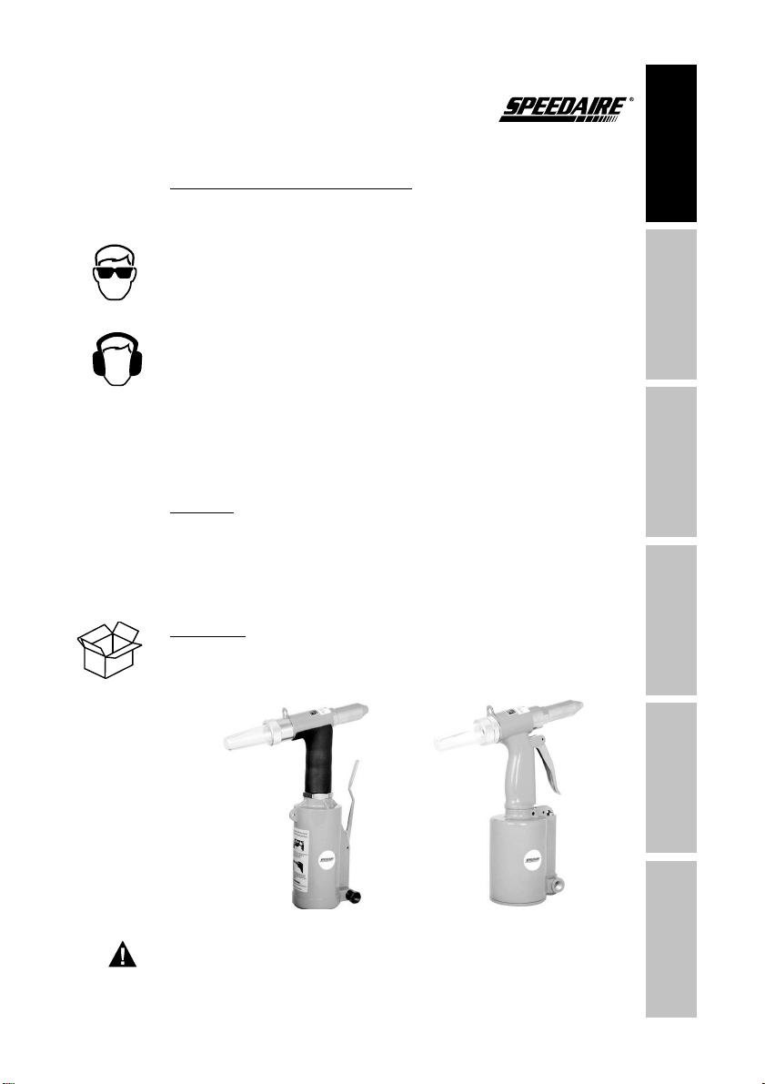
AIR RIVETER
Models 3CRH3B and 3CRH4B

PLEASE READ AND SAVE
THESE INSTRUCTIONS.
READ CAREFULLY
GNITPMETTAEROFEB
,LLATSNI,ELBMESSAOT
OPERATE OR MAINTAIN THE
PRODUCT DESCRIBED.
PROTECT YOURSELF AND
OTHERS BY OBSERVING ALL
SAFETY INFORMATION. FAILURE
TO COMPLY WITH INSTRUCTIONS
COULD RESULT IN PERSONAL
INJURY AND/OR PROPERTY DAMAGE!
RETAIN INSTRUCTIONS FOR FUTURE
REFERENCE.
PLEASE REFER TO BACK COVER
FOR INFORMATION REGARDING
DAYTON’S WARRANTY AND OTHER
IMPORTANT INFORMATION.
Model #: ___________________
Serial #: ___________________
Purch. Date: _______________
© 2015 W.W. Grainger, Inc.
All Rights Reserved
Printed in Taiwan
Version //201
BEFORE YOU BEGIN
GETTING STARTED SAFETY /
SPECIFICATIONS
ASSEMBLY /
INSTALLATION OPERATION TROUBLESHOOTING MAINTENANCE /
REPAIR
See General Safety Instructions on page 2, and Cautions and Warnings
as shown.
1
Personal protection equipment
Unpack:
parts. Shipping damage claim must be filed with the carrier.
Contents:
UNPACKING

GENERAL SAFETY INFORMATION
GETTING STARTED
SAFETY /
SPECIFICATIONS
ASSEMBLY /
INSTALLATION
OPERATIONTROUBLESHOOTING
MAINTENANCE /
REPAIR
2
Some dust created by power sanding, sawing,
grinding, drilling, and other construction activities
contains chemicals known to cause cancer, birth defects or other
reproductive harm. Some examples of these chemicals are:
"
area, and work with approved safety equipment, such as those dust masks
that air specially designed to filter out microscopic particle.

SPECIFICATIONS
GETTING STARTED SAFETY /
SPECIFICATIONS
ASSEMBLY /
INSTALLATION OPERATION TROUBLESHOOTING MAINTENANCE /
REPAIR
3
3CRH3B 3CRH4B
Rivet Sizes or Rivet Nut Sizes 3/16”
5/32”
1/8”
3/16”
5/32”
1/8”
3/32”
Pulling Force (Ibs) 1983
Stroke
Maximum Air Pressure (PSI)
Air Consumption per Stroke
(CFM)
Air Inlet (NPT)
Recommended Hose Size 3/8” 3/8”
Hydraulic oil
Overall Length
Overall Height
Overall Width

GETTING STARTED
SAFETY /
SPECIFICATIONS
ASSEMBLY /
INSTALLATION
OPERATIONTROUBLESHOOTING
MAINTENANCE /
REPAIR
Loosen and remove the nosepiece from the frame head as
shown, and replace it with the desired nosepiece.
INSTALLATION INSTRUCTIONS
Figure 1
Figure 2
Inner Dia. of
Nosepiece
Outer Dia. of
Rivets Available
Nosepiece display
3/32”
1/8"
5/32"
3/16"
GETTING STARTED SAFETY /
SPECIFICATIONS
ASSEMBLY /
INSTALLATION OPERATION TROUBLESHOOTING MAINTENANCE /
REPAIR
5
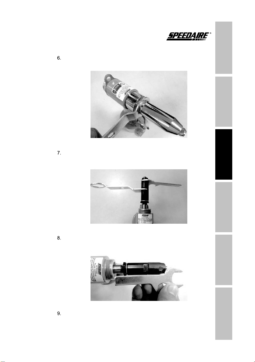
Loosen and remove the frame head from the frame, then loosen
and remove the front jaw case from the rear jaw case.
Take out the jaw and jaw pusher, and replace with the jaw and
jaw pusher that correspond to the nosepiece installed above.
Assemble the jaw housing and adjust its length using the spanner
gauge as shown.
Re-assemble the frame head and lock it with the corresponding,
previously loosened lock nut.
INSTALLATION INSTRUCTIONS
Figure 3
Figure 4
Figure 5

GETTING STARTED
SAFETY /
SPECIFICATIONS
ASSEMBLY /
INSTALLATION
OPERATIONTROUBLESHOOTING
MAINTENANCE /
REPAIR
1. Select rivet size and ensure riveter nosepiece size matches.
See “Assembly” section for instructions for changing the nosepiece.
2. Insert rivet mandrel into nosepiece.
3. Insert rivet body into material to be riveted.
4. Squeeze the trigger to attach the rivet.
Figure 6
Figure 7
OPERATING INSTRUCTIONS
6

GETTING STARTED SAFETY /
SPECIFICATIONS
ASSEMBLY /
INSTALLATION OPERATION TROUBLESHOOTING MAINTENANCE /
REPAIR
TROUBLESHOOTING
Symptom Possible Causes Corrective Action
j
f
cf h
isassemble the air cylinder, frame
and frame head.
Before adding oil, check if
the oil piston is at the bottom of its
stroke by hand pulling the front jaw
case away from the frame.
The oil piston should be at the
bottom of its stroke automatically when
removing the frame head.
WKHIUDPHWRWKHOHYHORI
WKHWRS
fh
FDVH
FQ
f
jh
spanner before
assembling frame head.

GETTING STARTED
SAFETY /
SPECIFICATIONS
ASSEMBLY /
INSTALLATION
OPERATIONTROUBLESHOOTING
MAINTENANCE /
REPAIR
TROUBLESHOOTING
Symptom Possible Causes Corrective Action
FF
V
M
sc
IK
M
K
5HOR
rivet,
FKLSVFDQVWLFNWRWKHQRVHSLHFH
malfunctioning
tv
c
v
8

GETTING STARTED SAFETY /
SPECIFICATIONS
ASSEMBLY /
INSTALLATION OPERATION TROUBLESHOOTING MAINTENANCE /
REPAIR
TROUBLESHOOTING
Symptom Possible Causes Corrective Action
V
36,
9
frame head/jaw housing/jaw/jaw pusher/
spring/jaw housing coupler
frame head/jaw housing/jaw/jaw pusher/spring
he mandrel bottle needs to be emptied when it is filled with
5 rivets' resideues.

GETTING STARTED
SAFETY /
SPECIFICATIONS
ASSEMBLY /
INSTALLATION
OPERATIONTROUBLESHOOTING
MAINTENANCE /
REPAIR
MAINTENANCE
V
WKH
VWURNHE\KDQGSXOOLQJWKH
IURQWMDZFDVHDZD\IURPWKHIUDPH
EHDWWKHERWWRPRILWVVWURNHZKHQ
UHPRYLQJ
KDQGSRZHU
WKH
WKH
IUDPHWRWKHOHYHORIWKHWRS25LQJ
IRURLODSSHDULQJLQWKHDLUF\OLQGHU
R
Jaw Inspection and Replacement
Pneumatic Oil

GETTING STARTED SAFETY /
SPECIFICATIONS
ASSEMBLY /
INSTALLATION OPERATION TROUBLESHOOTING MAINTENANCE /
REPAIR
MAINTENANCE
11
GETTING STARTED
SAFETY /
SPECIFICATIONS
ASSEMBLY /
INSTALLATION
OPERATIONTROUBLESHOOTING
MAINTENANCE /
REPAIR
12
For Repair Parts, call 1-800-323-0620
24 hours a day – 365 days a year
Please provide following information:
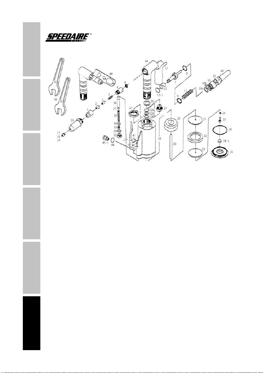
REPAIR PARTS ILLUSTRATION FOR 3CRH3B


GETTING STARTED
SAFETY /
SPECIFICATIONS
ASSEMBLY /
INSTALLATION
OPERATIONTROUBLESHOOTING
MAINTENANCE /
REPAIR
Description Part No. Qty.
32 *** 1
33 *** 1
*** 1
*** 1
35 *** 1
36 *** 1
*** 1
38 *** 1
39 1
*** 1
*** 1
*** 1
*** 1
*** 1
*** 1
*** 1
*** 2
REPAIR PARTS LIST FOR 3CRH3B

GETTING STARTED SAFETY /
SPECIFICATIONS
ASSEMBLY /
INSTALLATION OPERATION TROUBLESHOOTING MAINTENANCE /
REPAIR
15
NOTES

GETTING STARTED
SAFETY /
SPECIFICATIONS
ASSEMBLY /
INSTALLATION
OPERATIONTROUBLESHOOTING
MAINTENANCE /
REPAIR
16
REPAIR PARTS ILLUSTRATION FOR 3CRH4B
For Repair Parts, call 1-800-323-0620
24 hours a day – 365 days a year
Please provide following information:

GETTING STARTED SAFETY /
SPECIFICATIONS
ASSEMBLY /
INSTALLATION OPERATION TROUBLESHOOTING MAINTENANCE /
REPAIR
REPAIR PARTS LIST FOR 3CRH4B
*** 1
*** 1
*** 1
*** 1
32 *** 1
33 *** 1
35 *** 1
Description Part No. Qty.
1
1
1
1D 1
*** 1
*** 1
02
*** 1
1
*** 1
*** 1
11 1
12 *** 1
13 *** 1
*** 2
15 *** 1
16 *** 1
*** 1
18 *** 1
19 *** 1
*** 1
21 *** 1
22 *** 1
23 *** 1
*** 1
25 *** 2
26 *** 1
*** 1
29 *** 1
*** 1

GETTING STARTED
SAFETY /
SPECIFICATIONS
ASSEMBLY /
INSTALLATION
OPERATIONTROUBLESHOOTING
MAINTENANCE /
REPAIR
Description Part No. Qty.
36 *** 1
*** 1
38 *** 1
39 *** 1
*** 1
*** 1
*** 1
*** 1
*** 1
*** 1
*** 1
*** 1
*** 1
*** 1
*** 1
51 *** 1
52 *** 1
REPAIR PARTS LIST FOR 3CRH4B
18
This manual suits for next models
1
Table of contents
Languages:
Other Speedaire Rivet Tools manuals


