SpeedEPart Agri-Fab 45-01841 User manual
PRINTED IN USA FORM NO. 48452 (REV. 7/03)
OWNERS MANUAL
MANUAL DEL USUARIO
NOTICE D’UTILISATION
CAUTION:
Read R les for
Safe Operation
and Instr ctions
Caref lly
Model No.
Modelo No.
Modèle No.
ATTENTION:
Lire et s ivre
attentivement les
instr ctions et consignes
de séc rité de cette
notice.
PRECAUCION:
Lea c idadosamente los
Procedimientos e
Instr cciones para la
Operación Seg ra de la
Máq ina.
• Assembly
• Safety
• Operation
• Maintenance
• Parts • Montaje
• Seg ridad
• Operación
• Mantenimiento
• Piezas de Rep esto
• Assemblage
• Séc rité
• Utilisation
• Entretien
• Pièces de Rechange
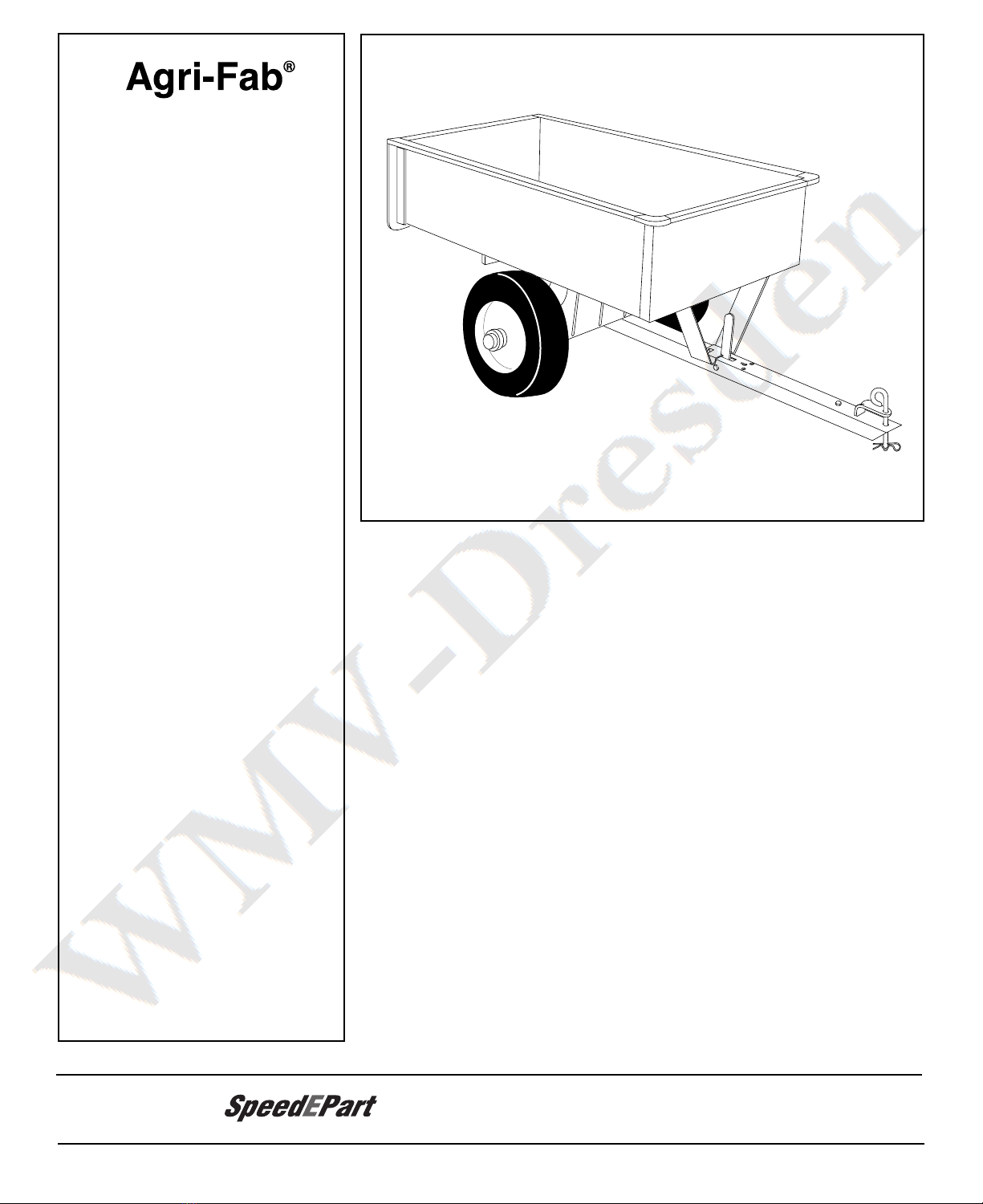
UTILITY CART
CARRITOS
REMORQUE UTILITAIRE
45-01841
45-02401
190-425A
the fastest way to purchase parts
www.speedepart.com
Agri-Fab
¨
Digitally signed by WMV-Dresden
DN: cn=WMV-Dresden, c=DE,
o=WMV-Dresden,
Date: 2017.01.26 13:00:47 +01'00'
WMV-
Dresden
2
SAFETY RULES
Remember, any power eq ipment can ca se inj ry if operated improperly or if the ser does not nderstand how
to operate the eq ipment. Exercise ca tion at all times when sing power eq ipment.
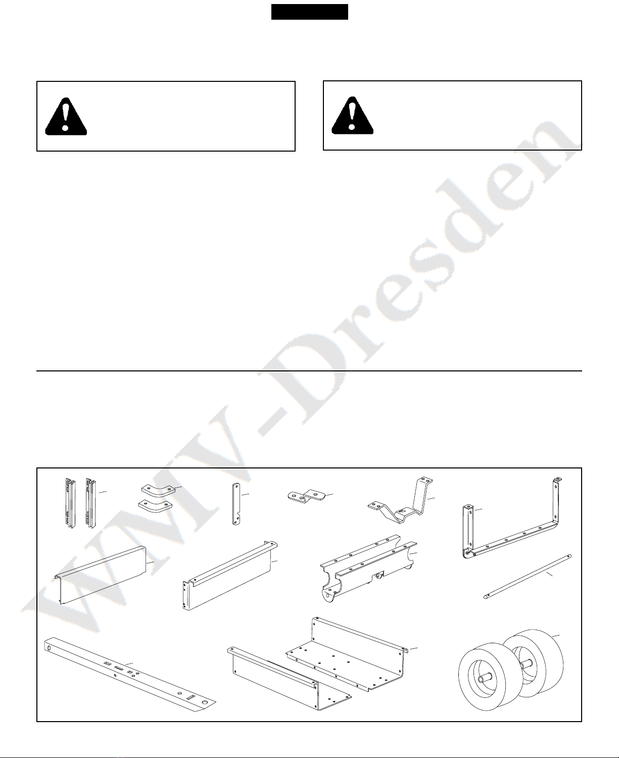
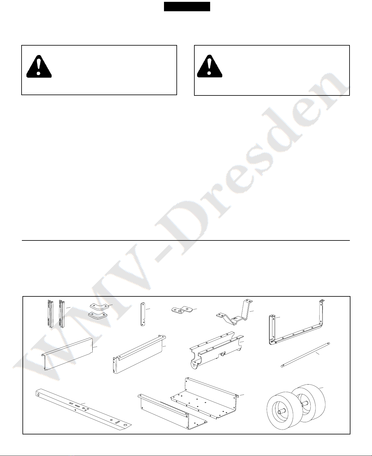
CARTON CONTENTS
LOOK FOR THIS SYMBOL TO POINT OUT
IMPORTANT SAFETY PRECAUTIONS. IT
MEANS -- ATTENTION! BECOME ALERT!
YOUR SAFETY IS INVOLVED.
5. Latch Stand Bracket
6. Tailgate Reinforcement Bracket
7. Tailgate
8. Front Panel
9. Wheel S pport
10. Axle
11. Draw Bar Tong e
12. Cart Body (2)
13. Wheels (2)
1. Tailgate G ides (2)
2. Corner Caps (2)
3. Latch Lock Lever
4. Hitch Bracket
CARTON CONTENTS (Loose Parts)
CAUTION: VEHICLE BRAKING AND
STABILITY MAY BE AFFECTED WITH
THE ADDITION OF AN ACCESSORY
OR AN ATTACHMENT. BE AWARE OF
CHANGING CONDITIONS ON SLOPES.
1. Read this owners man al before attempting to assemble or operate the cart.
2. Read the vehicle owners man al and know how to operate yo r tractor, before sing the cart attachment.
3. Do not at any time carry passengers in this cart. It has not been designed to carry passengers.
4. Never allow children to operate the tractor or the cart attachment.
5. Do not allow ad lts to operate the tractor or cart attachment witho t proper instr ctions.
6. Always begin with the transmission in first (low) and grad ally increase speed as conditions permit.
7. Tow the cart at red ced speed over ro gh terrain and hillsides or near creeks and ditches to prevent tipping
over and loss of control. Do not drive too close to a creek or ditch.
8. Vehicle braking and stability may be affected with the attachment of this cart. Do not fill cart to maxim m weight
capacity witho t checking the capability of the towing vehicle to safely p ll and stop with the cart attached.
9. Before operating vehicle on any grade (hill) refer to the safety r les in the vehicle owner's man al concerning
safe operation on slopes. Refer also to the slope g ide on page 9 of this man al. Stay off steep slopes!
10. Do not tow this cart on highways or on p blic thoro ghfares.
11. Maxim m towing speed is 10 m.p.h.
12. Follow maintenance and l brication instr ctions as o tlined in this man al.
135
4
2
10
13
12
9
11
8
7
6
ENGLISH
3
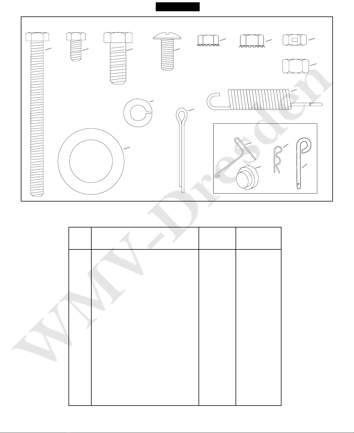
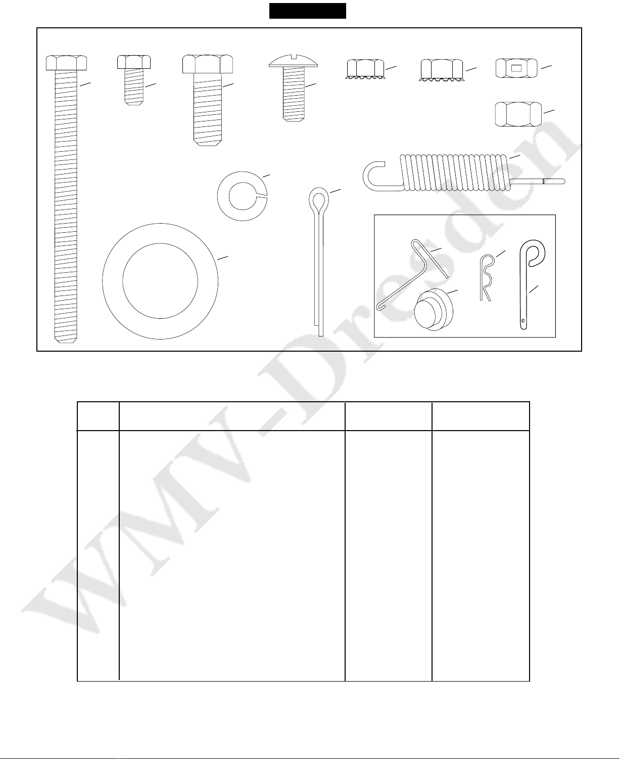
FIGURE 1 - HARDWARE PACK
Ref. Description 45-02401 45-01841
190-425A
A Hex Bolt, 5/16-18 x 3-3/4" 1 1
B Hex Bolt, 1/4" x 1/2" 23 24
C Hex Bolt, 3/8" x 1" 1 1
D Tr ss Hd. Bolt, 5/16" x 3/4" 12 12
E Hex N t, 1/4" 23 24
F Hex N t, 5/16" 14 14
G Hex Lock N t, 5/16" 1 1
H Hex N t, 3/8" 1 1
I Lock Washer, 3/8" 1 1
J Flat Washer, 1" 4 4
K Cotter Pin, 1/8" x 1-1/2" Lg. 2 2
L Spring 1 1
M Spring P ller Tool 1 1
N H b Cap 2 2
O Hair Cottter Pin 1/8" 1 1
P Hitch Pin 1 1
B C D
E
I
J
K
L
N
Not Shown Full Size
HARDWARE SHOWN FULL SIZE
A
MO
H
FG
P
ENGLISH
4
ASSEMBLY INSTRUCTIONS
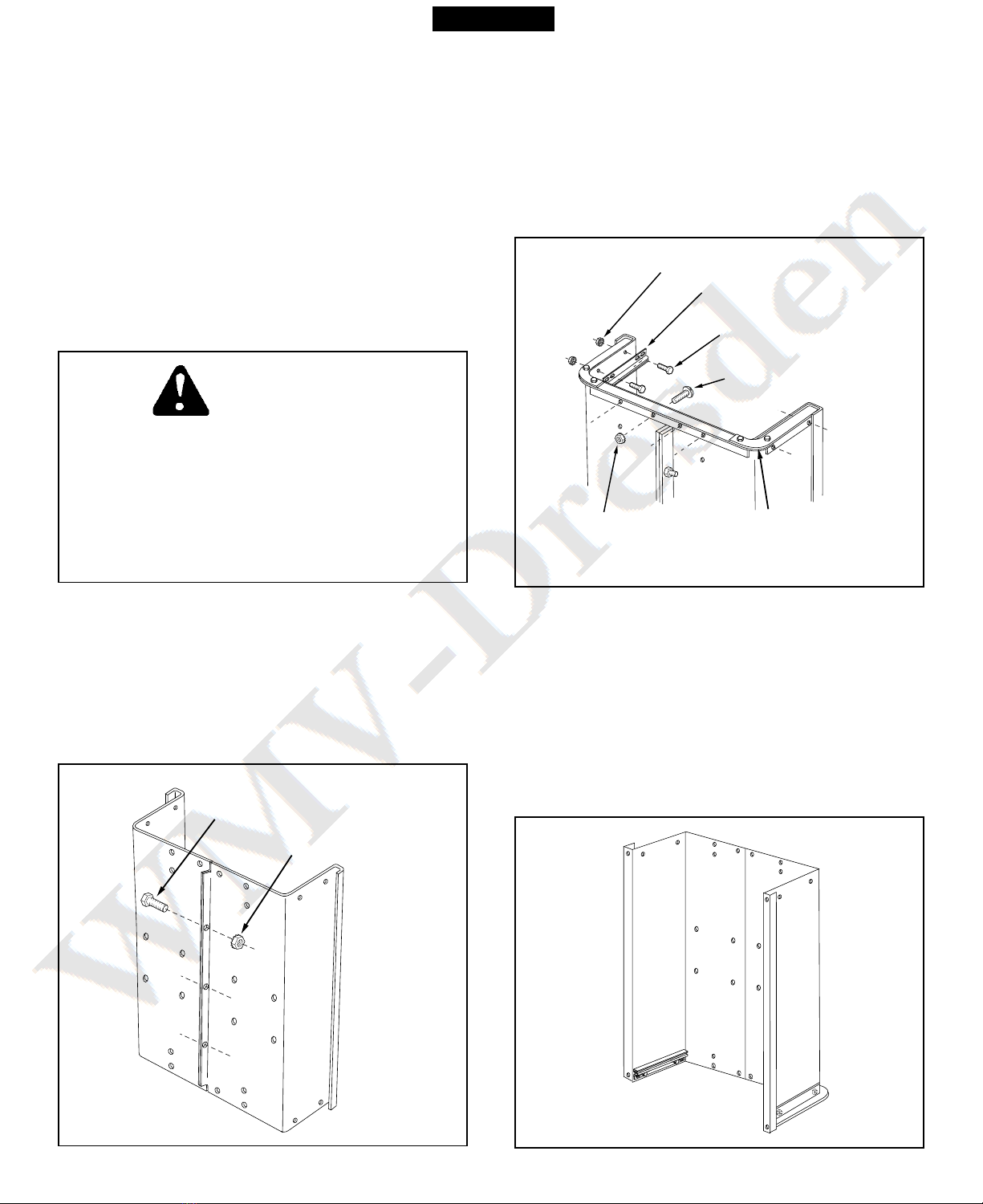
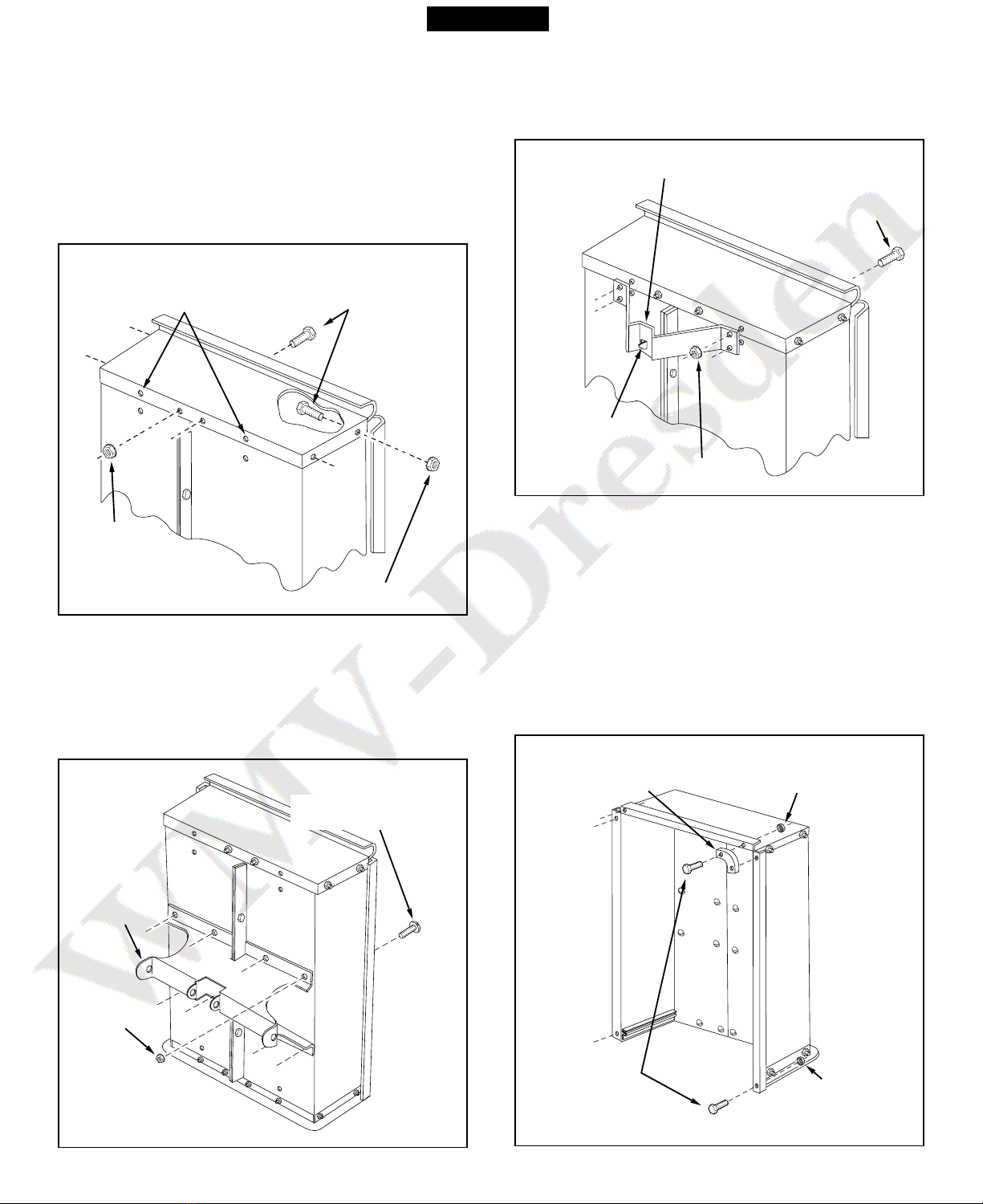
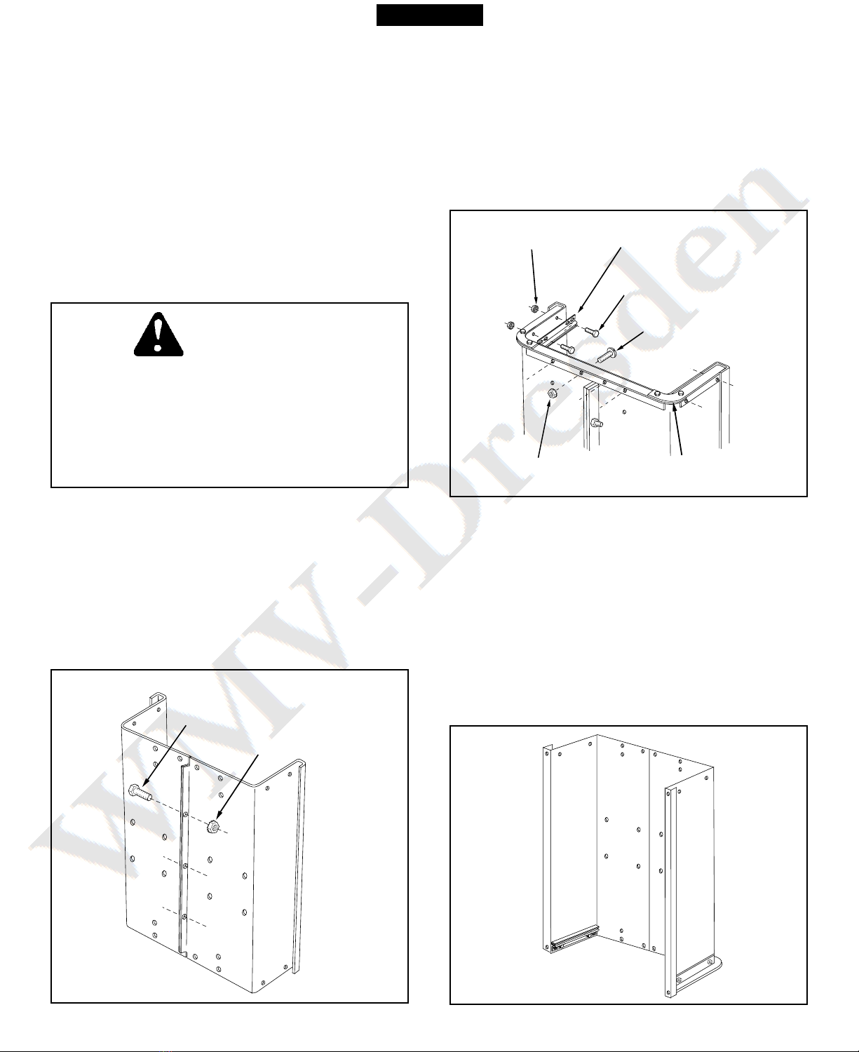
FIGURE 2
5. Position the tailgate reinforcement bracket on
o tside of cart as shown in fig re 3. Assemble to
the bottom of the cart body sing fo r 5/16" x 3/4"
tr ss head bolts and 5/16" hex n ts. Do not tighten
yet. See fig re 3.
6. Position the tailgate g ides on the inside of the
cart bodies with g ide channels to the front as
shown in fig re 3. Assemble sing fo r 1/4" x 1/2"
hex bolts and 1/4" hex n ts. Do not tighten yet.
See fig re 3.
FIGURE 3
FIGURE 4
7. At this time, with the cart body halves p lled
together, tighten the fo r tr ss head bolts
assembled in step 5 and then the fo r hex bolts
assembled in step 6. Leave loose for now the bolts
that were assembled in step 4.
8. Caref lly reverse the position of the cart so that it
rests on the end with the j st assembled tailgate
reinforcement bracket, as shown in fig re 4. Proceed
with the assembly steps which follow.
DO NOT LEAVE THE CART UNATTENDED IN
UPRIGHT POSITION DURING ASSEMBLY. A
FALLINGCARTCANCAUSEPERSONALINJURY!
PAY CLOSE ATTENTION TO THE STABILITY OF
THE CART WHILE IT REMAINS IN AN UPRIGHT
POSITION. FOR BEST STABILITY, ASSEMBLE
ON A SMOOTH, LEVEL SURFACE.
CAUTION
TOOLS REQUIRED FOR ASSEMBLY
(1) Screwdriver
(1) Pliers
(2) 7/16" Wrenches
(2) 1/2" Wrench
(2) 9/16" Wrenches
1. Remove the hardware pack and all loose parts
from the carton. Be s re the carton is empty
before discarding.
2. Lay o t all the parts as shown in the carton con-
tents.
3. Position cart body halves pright on a smooth
level s rface s ch as a garage floor or a paved
driveway. See fig re 2.
4. Assemble halves together sing three 1/4" x 1/2"
hex bolts and 1/4" hex n ts as shown in fig re 2.
Do not tighten yet.
Note: The 45-01841 and 190-425A carts se fo r
bolts and n ts.
1/4" x 1/2" HEX BOLT
1/4" HEX NUT
1/4" x 1/2"
HEX BOLT
5/16" x 3/4"
TRUSS HEAD BOLT
5/16" HEX NUT
1/4" HEX NUT
TAILGATE
REINFORCEMENT
BRACKET
TAILGATE GUIDE
ENGLISH
5
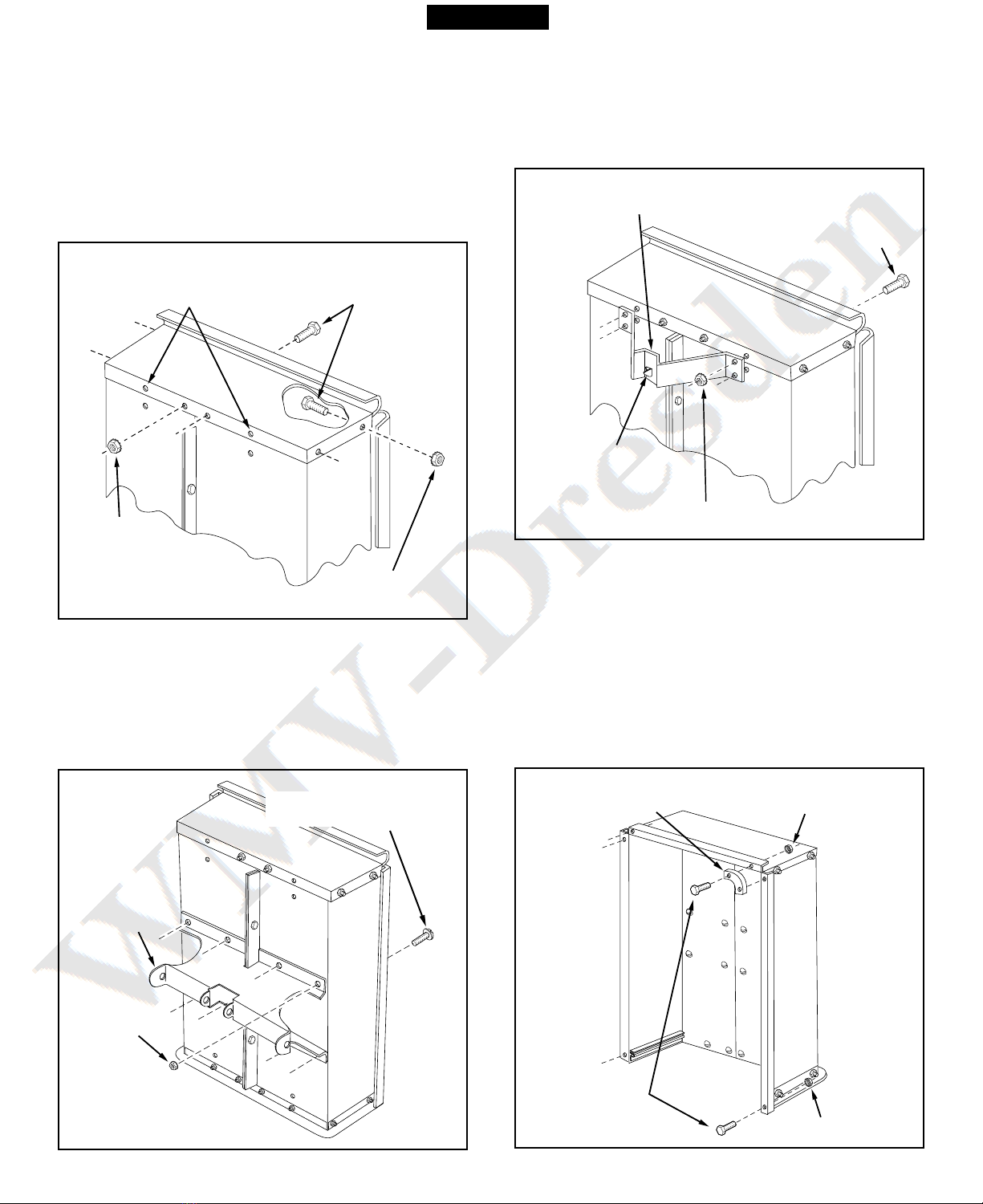
FIGURE 6
FIGURE 7
10. Assemble the wheel s pport to the cart sing eight
5/16" x 3/4" tr ss head bolts and 5/16" hex n ts as
shown in fig re 6. Heads of bolts go on the inside
of the cart. Tighten.
FIGURE 5
9. Assemble the front panel over the end of the cart
sing six 1/4" x 1/2" hex bolts and 1/4" hex n ts as
shown in fig re 5. Leave two holes in the bottom of
the panel empty as shown. With the cart body
halves p lled together, tighten the bolts in the
bottom of the front panel, then tighten the bolts in
the sides. See fig re 5.
At this time tighten the bolts assembled in step 4,
which fasten the bottom of the cart together.
FIGURE 8
12. Assemble the two corner caps to the front corners of
the cart sing fo r 1/4" x 1/2" hex bolts and 1/4" hex
n ts. Also assemble two 1/4" x 1/2" hex bolts and
1/4" hex n ts to the two rear corners of the cart.
TIGHTEN. See fig re 8.
11. T rn the latch stand bracket so that the aligning tab
is at the rear (bottom) of the bracket. Assemble the
latch stand bracket to the cart sing fo r 1/4" x 1/2"
hex bolts and 1/4" hex n ts. TIGHTEN. See fig re 7.
1/4" x 1/2"
HEX BOLTS
1/4" HEX NUT
1/4" HEX NUT
LEAVE HOLES OPEN FOR
LATCH STAND BRACKET
5/16" HEX
NUT
WHEEL
SUPPORT
5/16" x 3/4"
TRUSS HEAD BOLT
1/4" x 1/2"
HEX BOLT
LATCH STAND BRACKET
1/4" HEX NUT
ALIGNING TAB
AT BOTTOM
CORNER CAP
1/4" x 1/2"
HEX BOLT
1/4" HEX NUT
1/4" HEX
NUT
ENGLISH
6
18. T rn cart over so that it rests right side p on its
wheels.
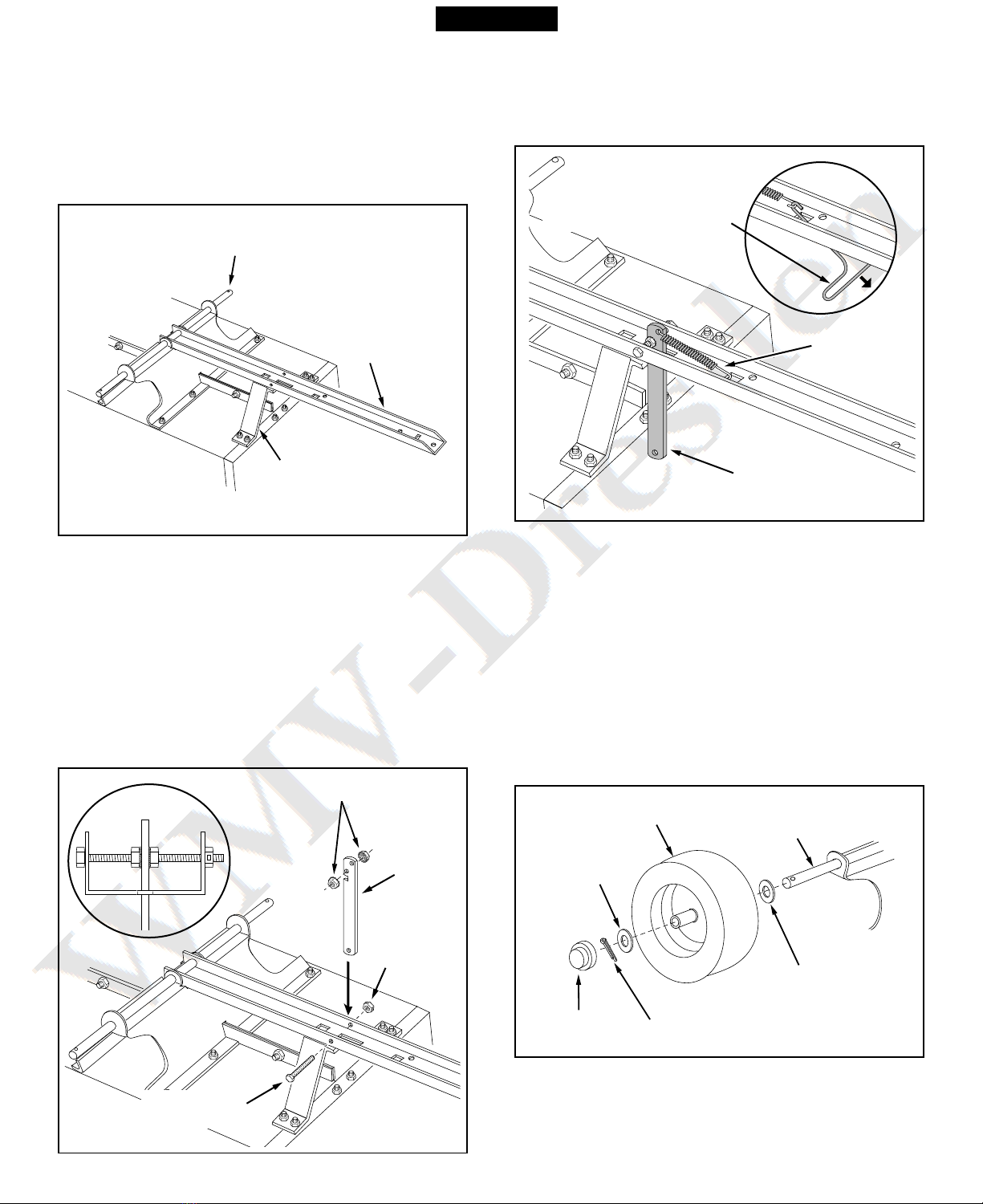
FIGURE 9
FIGURE 10
FIGURE 11
FIGURE 12
IMPORTANT: Make s re drawbar tong e is sec rely
locked to the latch stand bracket by the latch lock
lever.
17. Assemble a flat washer, a wheel with the valve stem
facing o t, and another flat washer onto the axle as
shown in fig re 12. Sec re the wheel on the axle with
a cotter pin, spreading the ends. Assemble the h b
cap by pressing it onto the flat washer. Repeat on
other end of axle.
15. Place the latch lock lever thro gh the slot in the draw
bar tong e as shown in fig re 10. Assemble the 5/16"
x 3-3/4" hex bolt thro gh the tong e, the lever and
two 5/16" hex n ts (one on each side of the lever).
Assemble the 5/16" hex lock n t onto the end of the
bolt and tighten so that the bolt can still rotate freely.
Tighten the two 5/16" hex n ts against the sides of
the latch lock lever so that the lever is centered in the
slot. See fig re 10.
AXLE
DRAW BAR
TONGUE
LATCH STAND
BRACKET
13. To prevent accidental tipping d ring the following
assembly proced res, lower the cart to rest pside
down on its top flanges, so that the wheel s pport is
facing p. See fig re 9.
14. Lay the drawbar tong e (open side facing p) onto
the Wheel S pport and the Latch Stand Bracket.
Assemble the axle thro gh the wheel s pport and the
tong e. See fig re 9.
5/16" HEX NUTS
5/16" HEX
LOCK NUT
LATCH
LOCK
LEVER
5/16" x 3-3/4"
HEX BOLT
COTTER PIN
WHEEL
HUB CAP
FLAT
WASHER
FLAT
WASHER
AXLE
ENGLISH
16. Hook the short end of the spring into the hole in the
latch lock lever. Use the spring p ller tool to hook the
long end of the spring into the sq are hole in the
tong e. The spring p ller tool can be stored when
finished. See fig re 11.
LONG END
OF SPRING
LATCH LOCK LEVER
SPRING PULLER TOOL
7
OPERATION
MAINTENANCE
1. At the beginning of each season, l bricate, with a
light machine oil, the latch, the latch pivot bolt,
and the area of the axle where the draw bar tong e
pivots .
2. Grease or oil the wheel bearings periodically. Use
a tomotive wheel bearing type grease or 20 weight
oil.
3. Keep tires filled to the recommended tire press re
of 12-14 Lbs.
1. Refer to the vehicle owners man al for instr ctions
on safe operation on slopes.
2. Use the slope g ide provided on page 9 of this
man al to determine if slope angle is not too steep for
safe operation.
3. For best handling and traction, distrib te the weight
of the load evenly in the cart.
4. Always test to make s re yo r tractor has adeq ate
towing and braking capabilities whenever ha ling a
s bstantial amo nt of weight in yo r cart. Use extra
ca tion when operating on slopes.
5. To d mp material from the cart, remove the tailgate
by lifting it straight p and o t from between the
g ides. Release the spring latch on the tong e by
p lling the latch lock lever forward, away from the
cart. The cart bed will then tilt backwards to empty its
contents. After emptying, p ll the front of the bed
down toward the cart tong e ntil the latch snaps into
place. Replace the tailgate if desired.
6. The maxim m towing speed for this cart is 10 m.p.h.
DO NOT EXCEED WEIGHT CAPACITY OF CART
(See the specifications on this page for each model)
One cubic foot of dirt weighs approximately 150 lbs.
MODEL 45-02401 - 15 Cu. Ft. (H.D.)
Tires: 16.00" x 6.5" Pne matic, T rf Tread
Axle: 1.0" Dia. Steel
Capacity: Up to 1200 Lbs. Max.
Approx. Sh. Wt.
157 Lbs.
MODELS 45-01841, 190-425A - 17 Cu. Ft. (H.D.)
Tires: 16.00" x 6.5" Pne matic, T rf Tread
Axle: 1.0" Dia. Steel
Capacity: Up to 1500 Lbs. Max.
Approx. Sh. Wt.
180 Lbs.
CART MODEL SPECIFICATIONS
CAUTION: TO AVOID POSSIBLE
INJURY, BEFORE RELEASING THE
LATCH BE SURE THAT NO ONE IS
NEAR THE CART.
CAUTION: VEHICLE BRAKING AND
STABILITY MAY BE AFFECTED WITH
THE ADDITION OF AN ACCESSORY
OR AN ATTACHMENT. BE AWARE OF
CHANGING CONDITIONS ON SLOPES.
NOTE
21. Place the tailgate down into the tailgate g ides so
that the holes in the bottom lip of tailgate fit over
the slotted head screws in the bottom of the cart.
This completes the assembly of yo r cart.
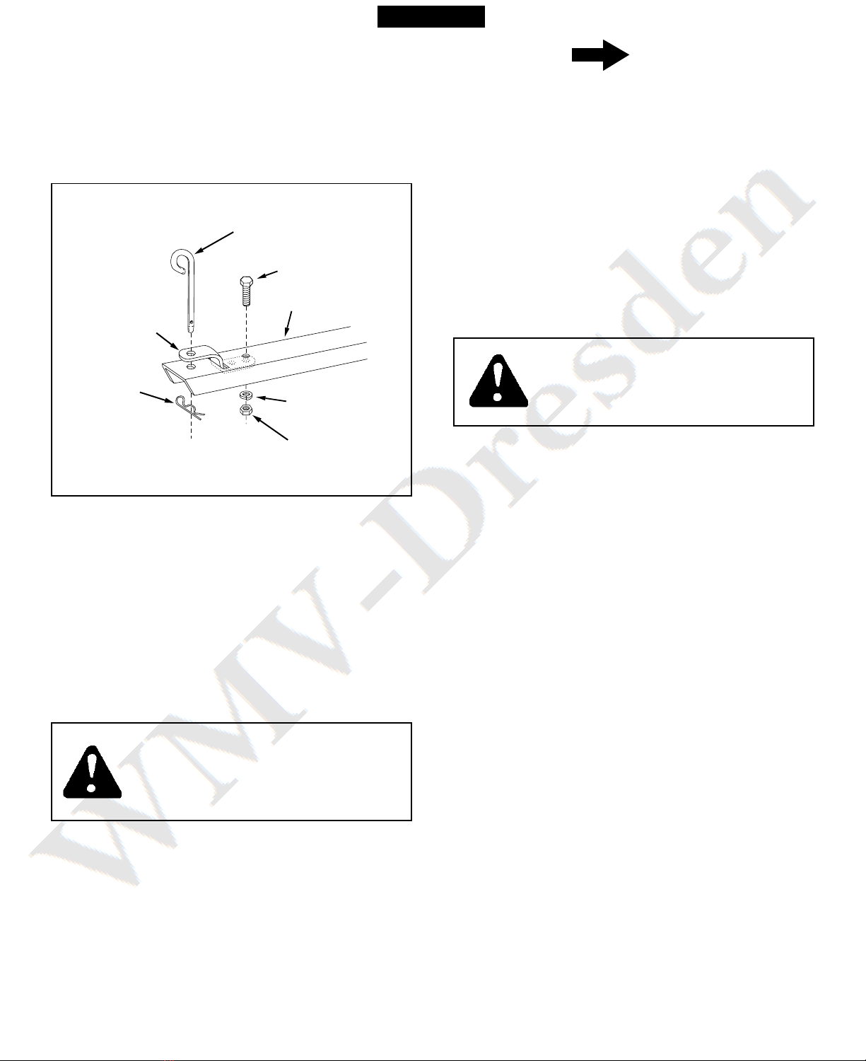
FIGURE 13
TONGUE
3/8" x 1"
HEX BOLT
3/8" LOCK
WASHER
3/8" HEX
NUT
HITCH
BRACKET
1/8" HAIR
COTTER
PIN
HITCH PIN
19. Assemble the end of the hitch bracket (two holes)
down thro gh the slot at the front of the drawbar
tong e. Fasten it to the tong e sing the 3/8" x 1"
hex bolt, 3/8" lock washer and 3/8" hex n t.
Tighten. See fig re 13.
20. Assemble the hitch pin thro gh the hitch bracket
and the tong e and sec re with the 1/8" hair cotter
pin. See fig re 13.
ENGLISH

8
ENGLISH
9
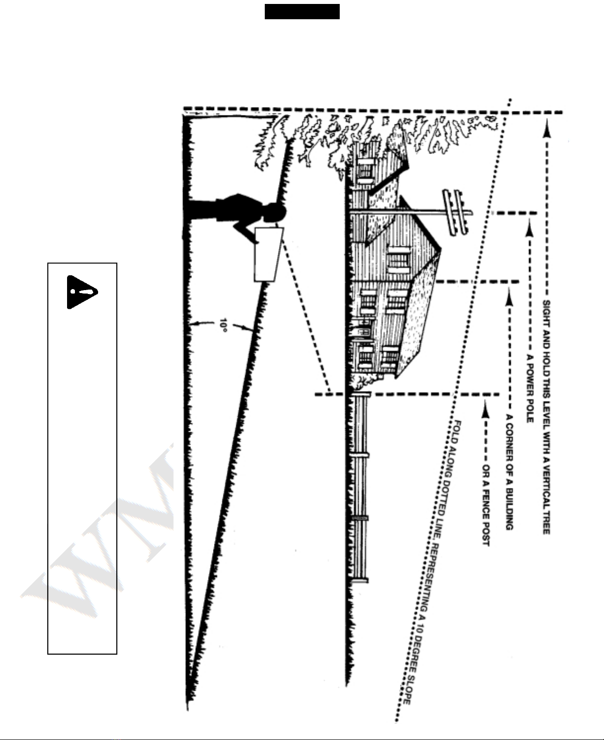
SLOPE GUIDE
(Keep this sheet in a safe place for future reference.)
Use this guide to determine if a slope is safe for the operation of your tractor and cart.
Refer also to the instructions in your vehicle owners manual.
CAUTION: DO NOT OPERATE YOUR TRACTOR AND CART ON
A SLOPE IN EXCESS OF 10 DEGREES. BE SURE OF YOUR
TRACTOR'S TOWING AND BRAKING CAPABILITIES BEFORE
OPERATING ON A SLOPE. AVOID ANY SUDDEN TURNS OR
MANEUVERS WHILE ON A SLOPE.
ENGLISH
10
REGLAS DE SEGURIDAD
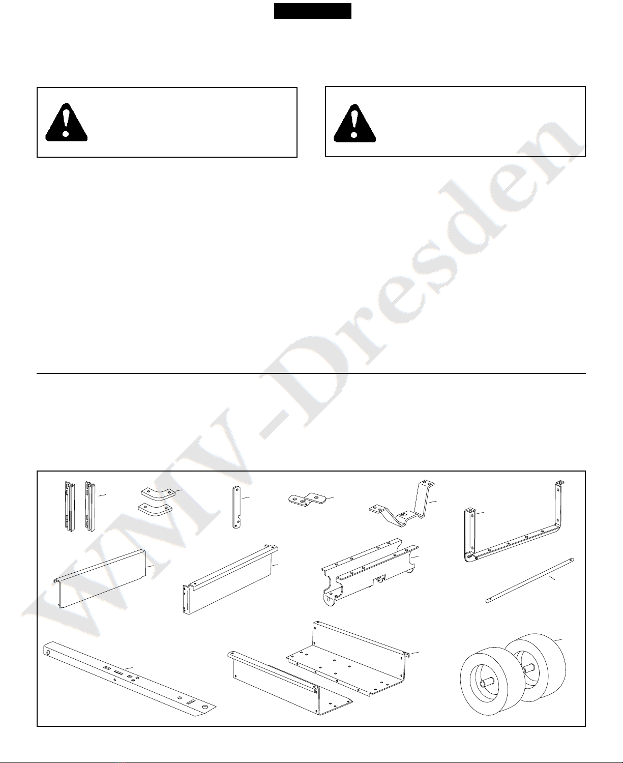
CONTENIDO DEL EMBALAJE
ESTE SIMBOLO INDICA PRECAUCIONES
IMPORTANTES DE SEGURIDAD. SIGNIFICA -
¡ATENCION! SU SEGURIDAD ESTA EN
RIESGO
5. Soporte de la base del cierre
6. Soporte de ref erzo de la p erta trasera
7. P erta trasera
8. Panel delantero
9. Soporte de las r edas
10. Eje
11. Lengüeta de enganche
12. C erpo del carrito (2)
13. R edas (2)
1. G ías de la p erta trasera (2)
2. Tapas para las esq inas (2)
3. Palanca de bloq eo del cierre
4. Soporte de enganche
CONTENIDO DEL EMBALAJE (Piezas s eltas)
PRECAUCION: LA ESTABILIDAD DEL
VEHICULO Y SU CAPACIDAD DE FRENADO
PUEDEN AFECTARSE AL REMOLCAR UN
ACCESORIO O UN VEHICULO ADICIONAL.
TENGA CUIDADO CON ESTE CAMBIO DE
CONDICIONES DEBIDO A LA PENDIENTE.
1. Lea este man al del s ario antes de ensamblar las piezas o sar el carrito
2. Lea el man al del s ario del vehíc lo de remolq e y aprenda cómo operar s tractor antes de sar el accesorio del
carrito.
3. N nca transporte a pasajeros en este carrito. No ha sido diseñado para transportar a pasajeros.
4. N nca permita q e los niños operen el tractor o el carrito.
5. No permita tampoco q e los ad ltos los operen sin haber recibido instr ccion adec ada.
6. Empiece siempre con la transmisión en primera (bajo) y con el motor a baja velocidad, y grad almente a mente la
velocidad según lo permitan las condiciones.
7. C ando remolq e el carrito, no cond zca demasiado cerca de arroyos o zanjas, y manténgase alerta en c anto a h ecos
otros peligros q e p edan ser ca sa de q e sted pierda el control del tractor y del carrito.
8. La estabilidad y capacidad de frenado del vehíc lo p eden afectarse al enganchar este carrito. No llene el carro a s
capacidad de peso máximo sin haber verificado la s ficiencia del vehíc lo tractor para remolcar el carro en forma seg ra
y frenar adec adamente con el carro enganchado.
9. Antes de operar el vehíc lo en c alq ier pendiente ( o colina), cons lte las reglas de seg ridad q e aparecen en el
man al del s ario del vehíc lo, relativas a la forma seg ra de operar en pendientes. Vea el g ia de la página 17.
¡Manténgase alejado de pendientes escarpadas!
10. No remolq e este carrito en carreteras o caminos públicos.
11. La máxima velocidad de remolq e es de 10 MPH (16 km/h).
12. Observe las instr cciones de mantenimiento y l bricación, según se describen en este man al.
135
4
2
10
13
12
9
11
8
7
6
C alq ier eq ipo movido por motor p ede ca sar lesiones si se opera inadec adamente o si el s ario no entiende cómo
debe operarlo. Manténgase atento y ca teloso siempre q e opere el eq ipo.
ESPAÑOL
11
FIGURA 1 - CONTENIDO DEL PAQUETE DE HERRAJES
Ref. Descripción 45-02401 45-01841
190-425A
A Tornillo con cabeza hex., 5/16-18 x 3-3/4" 1 1
B Tornillo con cabeza hex., 1/4" x 1/2" 23 24
C Tornillo con cabeza hex., 3/8" x 1" 1 1
D Tornillo con cabeza reforzada 5/16" x 3/4" 12 12
E T erca hex, 1/4" 23 24
F T erca hex, 5/16" 14 14
G T erca de bloq eo hex, 5/16" 1 1
H T erca hex, 3/8" 1 1
I Arandela de bloq eo, 3/8" 1 1
J Arandela plana, 1" 4 4
K Pasador de aletas, 1/8" x 1-1/2" Lg. 2 2
L M elle largo 1 1
M Extractor de m elles 1 1
N Tapa del c bo 2 2
O Pasador de aleta Espiral, 1/8" 1 1
P Pasador de enganche 1 1
B C D
E
I
J
K
L
N
No se Muestran a Tama o Real
HERRAJES MOSTRADOS A TAMA O REAL
A
MO
H
FG
P
ESPAÑOL
12
INSTRUCCIONES DE MONTAJE
FIGURA 2
VIGILE EL CARRITO CUANDO LO TENGA DE PIE DU-
RANTE EL MONTAJE. ¡LA CAÍDA DE UN CARRITO PUEDE
PROVOCAR DAÑOS PERSONALES! PRESTE ATENCIÓN
A LA ESTABILIDAD DEL CARRITO MIENTRAS SE
ENCUENTRE DE PIE. PARA CONSEGUIR UNA MEJOR
ESTABILIDAD, MÓNTELO SOBRE UNA SUPERFICIE
PLANA Y NIVELADA.
PRECAUCION
HERRAMIENTAS NECESARIAS PARA EL MONTAJE
(1) Destornillador
(1) Alicates
(2) Llaves de 7/16"
(2) Llave de 1/2"
(2) Llaves de 9/16"
1. Saq e el pack de tornillería y todas las piezas s eltas
del embalaje. Asegúrese de q e el embalaje está vacío
antes de tirarlo.
2. Disponga todas las piezas tal y como se m estra en los
contenidos del embalaje.
3. Coloq e de pie las dos mitades del c erpo del carrito
sobre na s perficie plana y nivelada, como el s elo de
n garaje o n camino pavimentado. Vea la fig ra 2.
4. Acople ambas mitades tilizando tres tornillos con
cabeza hexagonal 1/4"x 1/2" y t ercas hexagonales
1/4", tal y como se m estra en la fig ra. No las apriete
todavía.
Nota: Los modelos de carrito 45-01841 y 190-425A tilizan
c atro tornillos y c atro t ercas.
TORNILLO DE
CABEZA HEX. 1/4" x 1/2"
TUERCA HEX. 1/4"
5. Coloq e el soporte de ref erzo de la p erta trasera en
la parte exterior del carrito, tal y como se m estra en la
fig ra 3. Acóplelo al c erpo del carrito tilizando c atro
tornillos de cabeza reforzada 5/16"x 3/4" y t ercas hex.
5/16". No las apriete todavía. Vea la fig ra 3.
6. Coloq e las g ías de la p erta trasera en la parte
interior de los c erpos del carrito con los canales de las
g ías sit ados en la parte delantera, tal y como se
m estra en la fig ra 3. Acóplelas tilizando c atro
tornillos con cabeza hex. 1/4"x 1/2" y t ercas hex. 1/4".
No las apriete todavía. Vea la fig ra 3.
FIGURA 3
FIGURA 4
7. En este momento, con las dos mitades del c erpo del
carrito j ntas, apriete los c atro tornillos con cabeza
reforzada colocados en el paso 5 y, a contin ación, los
c atro tornillos con cabeza hex. colocados en el paso
6. De momento, deje flojos los tornillos colocados en el
paso 4.
8. Con m cho c idado, invierta la posición del carrito, de
modo q e descanse sobre el extremo con elsoporte
de ref erzo de la p erta trasera recién montado, tal y
como se m estra en la fig ra 4. Prosiga con los pasos
de montaje q e se indican a contin ación.
TORNILLO DE CABEZA
HEX. 1/4" x 1/2"
TORNILLO DE CABEZA
REFORZADA 5/16" x 3/4"
TUERCA
HEX. 5/16"
TUERCA HEX. 1/4"
SOPORTE DE REFUERZO
DE LA PUERTA TRASERA
GUIA DE LA
PUERTA TRASERA
ESPAÑOL
13
FIGURA 6
FIGURA 7
10. Acople el soporte de las r edas al carrito tilizando
ocho tornillos con cabeza reforzada 5/16"x 3/4" y t ercas
hexagonales 5/16", tal y como se m estra en la fig ra
6. Las cabezas de los tornillos deben q edar en la parte
interior del carrito. Apriete.
FIGURA 5
9. Monte el panel delantero sobre el extremo del carrito
tilizando seis tornillos con cabeza hex. 1/4"x 1/2" y
t ercas hexagonales1/4", tal y como se m estra en la
fig ra 5. Deje dos orificios vacíos en la parte inferior del
panel, tal y como se m estra. Con ambas mitades del
c erpo del carrito j ntas, apriete los tornillos de la
parte inferior del panel delantero, a contin ación apriete
los tornillos a ambos lados. Vea la fig ra 5.
En este momento, apriete los tornillos montados en el
paso 4, q e fijan la parte la parte inferior del carrito.
FIGURA 8
12. Coloq e las dos tapas de las esq inas en las esq inas
delanteras del carrito tilizando c atro tornillos con
cabeza hexagonal 1/4"x 1/2" y t ercas hexagonales
1/4". Coloq e también dos tornillos con cabeza hex-
agonal 1/4"x 1/2" y t ercas hexagonales 1/4" en las dos
esq inas traseras del carrito. APRIETE. Vea la fig ra
8.
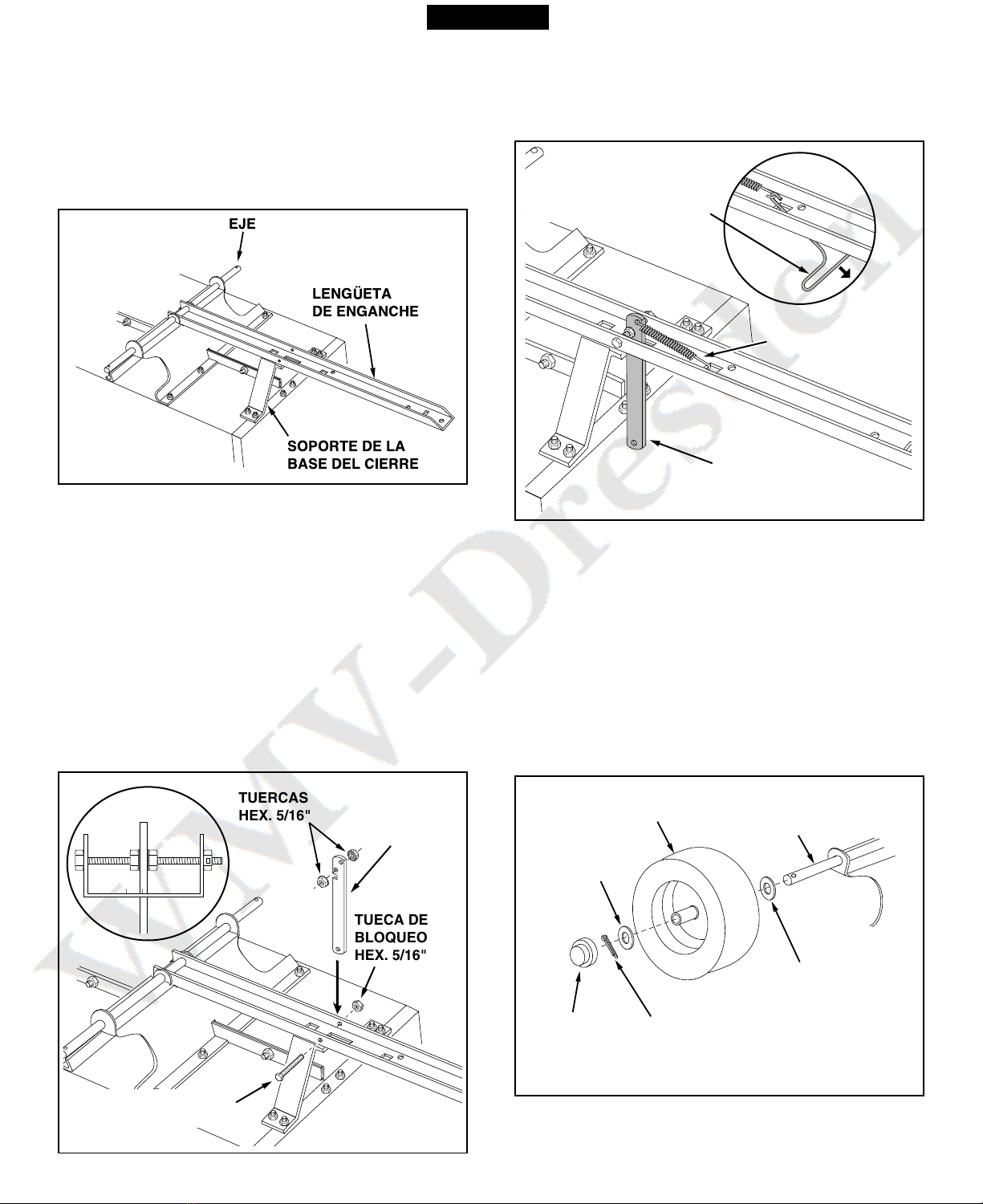
11. Gire el soporte de la base del cierre, de modo q e la
lengüeta de alineación q ede en la parte de atrás
(parte inferior) del soporte. Monte el soporte de la base
del cierre en el carrito tilizando c atro tornillos con
cabeza hexagonal 1/4"x 1/2" y t ercas hexagonales
1/4". APRIETE. Vea la fig ra 7.
TORNILLOS DE
CABEZA HEX.
1/4" x 1/2"
TUERCA
HEX. 1/4"
TUERCA
HEX. 1/4"
DEJE LOS AGUJEROS
ABIERTOS PARA EL SOPORTE
DE LA BASE DEL CIERRE
TUERCA
HEX. 5/16"
SOPORTE
DE RUEDA
TORNILLO DE CABEZA
REFORZADA 5/16" x 3/4"
TORNILLO DE
CABEZA HEX.
1/4" x 1/2"
SOPORTE DE LA
BASE DEL CIERRE
TUERCA HEX. 1/4"
ALINEAR LA
LENG ETA
DEL FONDO
TAPAS PARA
ESQUINAS
TORNILLO
DE CABEZA
HEX. 1/4" x 1/2"
TUERCA HEX. 1/4"
TUERCA HEX. 1/4"
ESPAÑOL
14
18. Gire el carrito, de modo q e descanse sobre s s r edas
q edando hacia arriba.
FIGURA 9
FIGURA 10
FIGURA 11
FIGURA 12
IMPORTANTE: Asegúrese de q e la lengüeta de enganche
q ede totalmente encajada en el soporte de la base del
cierre mediante la palanca de bloq eo del cierre.
17. Coloq e na arandela plana, n r eda con la válv la
del ne mático mirando hacia f era y otra arandela
plana en el eje, tal y como se m estra en la fig ra 12.
Fije la r eda al eje con n pasador de aletas,
desplegando los extremos. Coloq e la tapa del c bo
presionándola sobre la arandela plana. Repita la
operación en el otro extremo del eje.
15. Pase la palanca de bloq eo del cierre a través de la
ran ra de la lengüeta de enganche, tal y como se
m estra en la fig ra 10. Pase el tornillo con cabeza
hexagonales de 5/16" x 3-3/4" a través de la lengüeta,
de la palanca y de dos t ercas hex. 5/16" ( na a cada
lado de la palanca). Coloq e la t erca de bloq eo hex.
5/16" en el extremo del tornillo y apriete, de modo q e
el tornillo todavía p eda girar libremente. Apriete las
dos t ercas hex. 5/16" contra los lados de la palanca
de bloq eo del cierre, de modo q e la palanca q ede
centrada en la ran ra. Vea la fig ra 10.
13. Para evitar la caída accidental d rante los sig ientes
pasos de montaje, baje el carrito y deje q e descanse
sobre s s bordes s periores, de modo q e el soporte
de las r edas q ede mirando hacia arriba. Vea la fig ra
9.
14. Coloq e la lengüeta de enganche (con la cara abierta
hacia arriba) sobre el soporte de las r edas y el soporte
de la base del cierre. Pase el eje a través del soporte
de las r edas y de la lengüeta. Vea la fig ra 9.
16. Coloq e el extremo corto del m elle en el orificio de la
palanca de bloq eo del cierre. Utilice n extractor de
m elles, tal y como se m estra en la fig ra 11, para
acoplar el extremo largo del m elle en el orificio
c adrado de la lengüeta.
EJE
LENGETA
DE ENGANCHE
SOPORTE DE LA
BASE DEL CIERRE
TUERCAS
HEX. 5/16"
TUECA DE
BLOQUEO
HEX. 5/16"
PALANCA
DE BLOQUEO
DEL CIERRE
TORNILLO DE CABEZA
HEX. 5/16" x 3-3/4"
PASADOR
DE ALETA
RUEDA
TAPA
DEL CUBO
ARANDELA
PLANA
ARANDELA
PLANA
EJE
ESPAÑOL
EXTREMO LARGO
DEL MUELLE
PALANCA DE
BLOQUEO
DEL CIERRE
EXTRACTOR DE MUELLE
15
OPERACIÒN
MANTENIMIENTO
1. Con cada cambio de estación, tilice aceite ligero para
máq inas para l bricar el cierre, el tornillo de giro del
cierre y la zona del eje en la q e gira la lengüeta de
enganche.
2. Engrase o l briq e con aceite los cojinetes de las
r edas de forma periódica. Utilice aceite de a tomoción
para cojinetes de r edas o aceite 20W.
3. Mantenga los ne máticos inflados a na presión
recomendada de 12-14 psi.
5. Para volcar el material del carrito, retire la p erta
trasera elevándola y sacándola de las g ías. S elte el
cierre del m elle de la lengüeta tirando de la palanca
de bloq eo del cierre hacia delante, alejándola del
carrito. La base del carrito se inclinará hacia atrás para
vaciar s contenido. Una vez vacío, tire de la parte
delantera de la base hacia la lengüeta del carrito hasta
q e el cierre q ede enganchado en s posición. V elva
a colocar la p erta trasera si así lo desea.
6. La velocidad de remolq e máxima para este carrito es
de 16,5 km/h.
NO SUPERE LA CAPACIDAD DE CARGA DEL CARRITO
(Cons lte las especificaciones en esta misma página para
cada no de los modelos)
30 cm cúbicos de tierra pesa, aprox., 68 kg.
MODELO 45-02401 - 0,42mcúbico (Trabajo Pesado)
Ne máticos: 16.00" x 6.5" especial para césped
Eje: 1.0" (2,5 cm) de Diá., acero
Capacidad: Hasta 600 kg. Máx.
Peso aprox: 78 kg
ESPECIFICACIONES DE LOS CARRITOS
21. Coloq e la p erta trasera en las g ías de la p erta
trasera, de modo q e los orificios del reborde inferior
de la p erta trasera encajen en los tornillos de cabeza
ran rada de la parte inferior del carrito. Con esta
operación finaliza el montaje de s carrito.
FIGURA 13
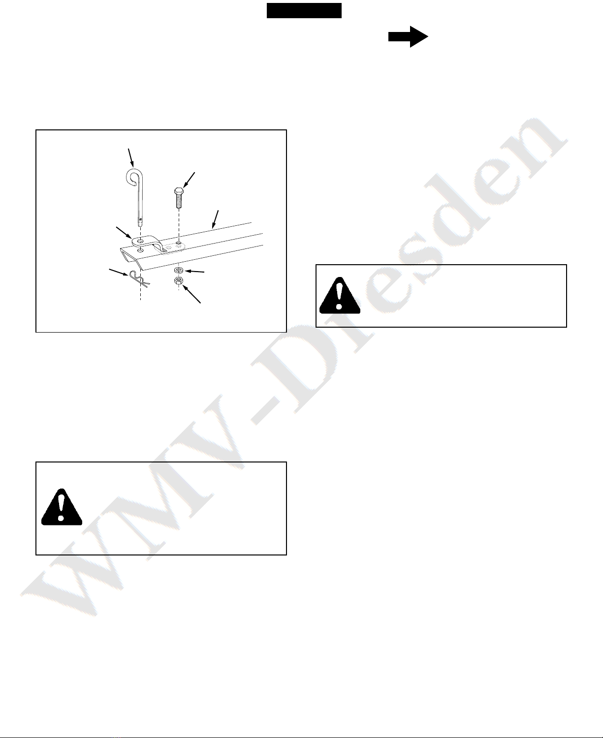
19. Pase el extremo del soporte de enganche (dos orificios)
a través de la ran ra sit ada en la parte delantera de la
lengüeta de enganche. Fíjelo a la lengüeta tilizando el
tornillo de cabeza hex. 3/8"x 1", la arandela de bloq eo
3/8" y la t erca hexagonal 3/8". Apriete. Vea la fig ra
13.
20. Pase el pasador de enganche a través del soporte de
enganche y de la lengüeta, y fíjelo con n pasador de
aletas espiral 1/8”. Vea la fig ra 13.
PRECAUCIÓN: LA CAPACIDAD DE
FRENADO Y LA ESTABILIDAD DEL
VEHÍCULO PUEDEN VERSE AFECTADAS
POR LA UTILIZACIÓN DE CUALQUIER
TIPO DE ACCESORIO. TENGA EN CUANTA
LAS CONDICIONES CAMBIANTES
CUANDO TRABAJE EN PENDIENTES.
PRECAUCIÓN: PARA EVITAR POSIBLES
DAÑOS PERSONALES, ANTES DE SOLTAR
EL CIERRE, ASEGÚRESE DE QUE NO HAY
NADIE JUNTO AL CARRITO.
MODELOS 45-01841, 190-425A - 0,48m cúb.
(Trabajo Pesado)
Ne máticos:16.00" x 6.5" especial para césped
Eje: 1.0" (2,5 cm) de Diá., acero
Capacidad: Hasta 750 kg. Máx.
Peso aprox: 90 kg
1. Cons lte el man al de s ario del vehíc lo para ver las
instr cciones sobre f ncionamiento seg ro en
pendientes.
2. Utilice la g ía de pendientes de la página 17 de este
man al para determinar si el áng lo de la pendiente es
demasiado pron nciado para n f ncionamiento seg ro.
3. Para conseg ir el mejor manejo y la mayor tracción
posibles, distrib ya el peso de la carga de forma
niforme en el carrito.
4. Asegúrese de q e s vehíc lo tractor tiene la capacidad
de remolq e y de frenado adec ada para remolcar na
cantidad de peso considerable en s carrito. Extreme
las preca ciones c ando trabaje en pendientes.
LENG ETA DE
ENGANCHE
TORNILLO DE
CABEZA HEX.
3/8" x 1"
ARANDELA
DE BLOQUEO
3/8"
TUERCA
HEX. 3/8"
SOPORTE DE
ENGANCHE
PASADOR
DE ALETA
ESPIRAL 1/8"
PASADOR DE ENGANCHE
NOTA
ESPAÑOL

16
ESPAÑOL
17
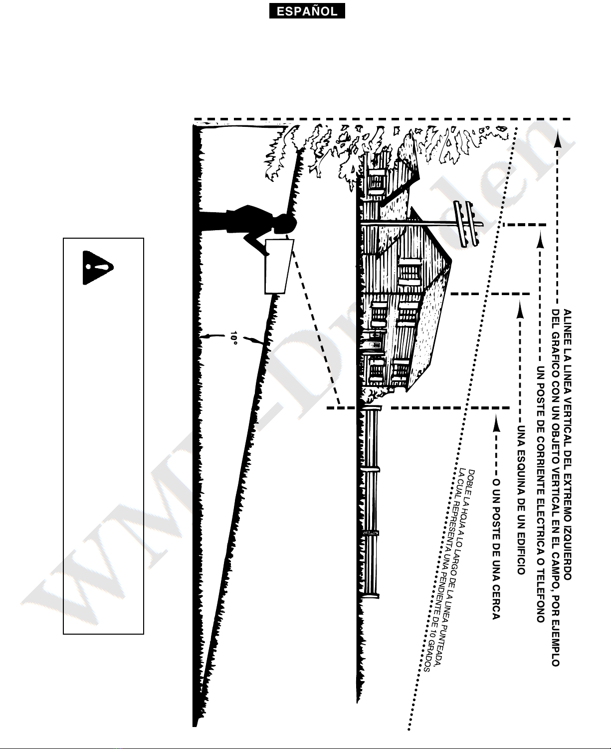
GUIA DE PENDIENTES
(Mantenga esta guía en un lugar seguro para referencia futura.)
Use esta guía para determinar si la operación de tractor y carrito es segura en una pendiente.
Consulte también las instrucciones en el Manual del Usuario de su vehículo.
PRECAUCION: NO OPERE EL TRACTOR REMOLCANDO EL
CARRO EN UNA PENDIENTE DE MAS DE 10°. VERIFIQUE LA
CAPACIDAD DE SU TRACTOR PARA REMOLCAR Y FRENAR
ADECUADAMENTE ANTES DE OPERAR EN UNA PENDIENTE.
EVITE GIROS O MANIOBRAS BRUSCAS CUANDO OPERA EN
UNA PENDIENTE.
UN POSTE DE CORRIENTE ELECTRICA O TELEFONO
UNA ESQUINA DE UN EDIFICIO
O UN POSTE DE UNA CERCA
DOBLE LA HOJA A LO LARGO DE LA LINEA PUNTEADA,
LA CUAL REPRESENTA UNA PENDIENTE DE 10 GRADOS
ALINEE LA LINEA VERTICAL DEL EXTREMO IZQUIERDO
DEL GRAFICO CON UN OBJETO VERTICAL EN EL CAMPO, POR EJEMPLO
ESPAÑOL
18
5. S pport de so tien d'attelage
6. S pport de consolidation d hayon
7. Hayon
8. Pannea avant
9. S pport de ro e
10. Essie
11. Barre de traction d'attelage
12. Carrosserie de remorq e (2)
13. Ro es (2)
1. G ides d hayon (2)
2. Barrettes en chapea d'angle (2)
3. Levier loq et de verro illage
4. S pport d'attelage
LISTE DU CONTENU DU CARTON (Pièces en v e éclatée)
135
4
2
10
13
12
9
11
8
7
6
SÉCURITÉ
To t appareil mécaniq e tilisé incorrectement pe t être la ca se de bless res. L’ tilisate r doit bien en maîtriser le fonctionnement.
Observez en to t temps la pl s grande pr dence lorsq e vo s tilisez n appareil mécaniq e.
ATTENTION: LA STABILITÉ ET LA
CAPACITÉ DE FREINAGE D’UN VÉHICULE
PEUT ÊTRE DIMINUÉE PAR L’AJOUT D’UN
ACCESSOIRE. SOYEZ VIGILANT DANS
LES PENTES.
1. Lisez attentivement ce man el avant d’assembler et d’ tiliser la remorq e.
2. Lisez le man el d’ tilisation d tracte r afin d’en bien maîtriser le fonctionnement avant d’y attacher la remorq e.
3. Ne jamais transporter de passagers dans la charrette p isq ’elle n’a pas été conç e à cet effet.
4. Les enfants ne devraient jamais être a torisés à tiliser le tracte r et la remorq e.
5. Les ad ltes q i n’ont pas reç d’instr ctions précises préalablement ne devraient pas tiliser ces appareils.
6. Démarrez to jo rs l’appareil à la pl s basse vitesse, p is a gmentez grad ellement si les conditions de terrain le permettent.
7. Tirez la charrette à vitesse réd ite en terrains accidentés o à flanc de cotea , près des fossés et des co rs d’ea , afin d’éviter de
basc ler o de perdre le contrôle. Évitez de cond ire près des fossés et des co rs d’ea .
8. Le freinage et la stabilité d véhic le pe vent être affectés par l’attache de cette charrette. Ne pas remplir la remorq e à capacité
maximale sans vérifier la tolérance d véhic le remorq e r à tirer et à s’arrêter avec cet accessoire.
9. Avant d’ tiliser le véhic le, référez-vo s a x règles de séc rité de votre man el de l’ tilisate r, partic lièrement en ce q i a trait à
la cond ite en pentes. Cons ltez également le g ide de ce man el à la page 25. Évitez les pentes abruptes!
10. Ne pas tiliser cette remorq e s r la voie p bliq e.
11. La vitesse maximale permise avec cet accessoire est de 16 km/he re.
12. S ivez les instr ctions d’entretien et de l brification de ce man el.
CE SYMBOLE ATTIRE L’ATTENTION SUR
DES MESURES DE SÉCURITÉ
IMPORTANTES. IL SIGNIFIE: «ATTENTION,
DEMEUREZ VIGILANT, VOTRE SÉCURITÉ
EN DÉPEND.»
FRANÇAIS
19
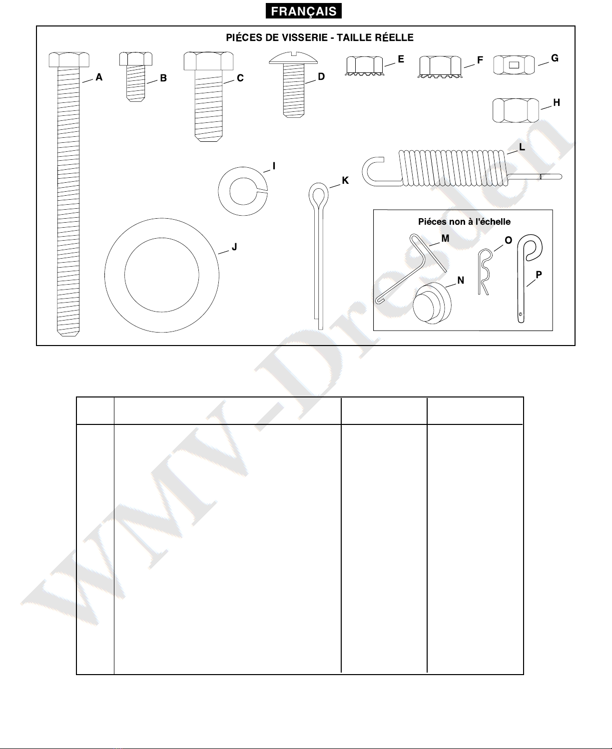
FIGURE 1 - VISSERIE ET PIÈCES DE QUINCAILLERIE
Réf. Description 45-02401 45-01841
190-425A
A Bo lon Hex , 5/16-18 x 3-3/4" 1 1
B Bo lon Hex , 1/4" x 1/2" 23 24
C Bo lon Hex , 3/8" x 1" 1 1
D Bo lon Tête bombée 5/16" x 3/4" 12 12
E Écro Hex, 1/4" 23 24
F Écro Hex, 5/16" 14 14
G Contre-écro , 5/16" 1 1
H Écro Hex., 3/8" 1 1
I Rondelle éventail, 3/8" 1 1
J Rondelle plate, 1" 4 4
K Go pille, 1/8" x 1-1/2" Lg. 2 2
L Ressort 1 1
M Extracte r de ressort 1 1
N Chapea de moye 2 2
O Go pille épingle, 1/8" 1 1
P Go pille d'attelage 1 1
B C D
E
I
J
K
L
N
A
MO
H
FG
P
PICES DE VISSERIE - TAILLE RELLE
Pices non l'chelle
FRANÇAIS
20
INSTRUCTIONS DE MONTAGE
FIGURE 2
ATTENTION
OUTILS REQUIS POUR LE MONTAGE
(1) To rnevis
(1) Pinces
(2) Clés 7/16"
(2) Clés 1/2"
(2) Clés 9/16"
NE LAISSEZ PAS LA REMORQUE SANS SURVEIL-
LANCE EN POSITION VERTICALE PENDANT
L'ASSEMBLAGE CAR ELLE RISQUE DE TOMBER ET
DE BLESSER QUELQU'UN. FAITES ATTENTION ÀLA
STABILITÉDE LA REMORQUE PENDANT QU'ELLE
DEMEURE EN POSITION VERTICALE. POUR PLUS DE
STABILITÉ, ASEMBLEZ LES PIÈCES SUR UNE SUR-
FACE LISSE ET ÀNIVEAU.
1. Enlevez hors d carton le sac de visserie et to tes les
pièces détachées. Ass rez-vo s q e le carton est vide
avant de vo s en débarrasser.
2. Etalez to tes les pièces comme indiq é dans la liste d
conten d carton.
3. Positionnez les éléments de moitié de carrosserie s r
ne s rface lisse et de nivea comme par exemple s r
le sol d' n garage o ne allée carrelée. Voir fig re 2.
4. Assemblez les moitiés l' ne à l'a tre en tilisant trois
bo lons hex. 1/4” x 1/2” et des écro s hex. 1/4” comme
montré dans la fig re 2. Ne serrez pas pour l'instant.
Note: La remorq e 45-01841 et modèle 190-425A tilise
q atre bo lons et écro s.
BOULON HEX. 1/4" x 1/2"
CROU HEX. 1/4"
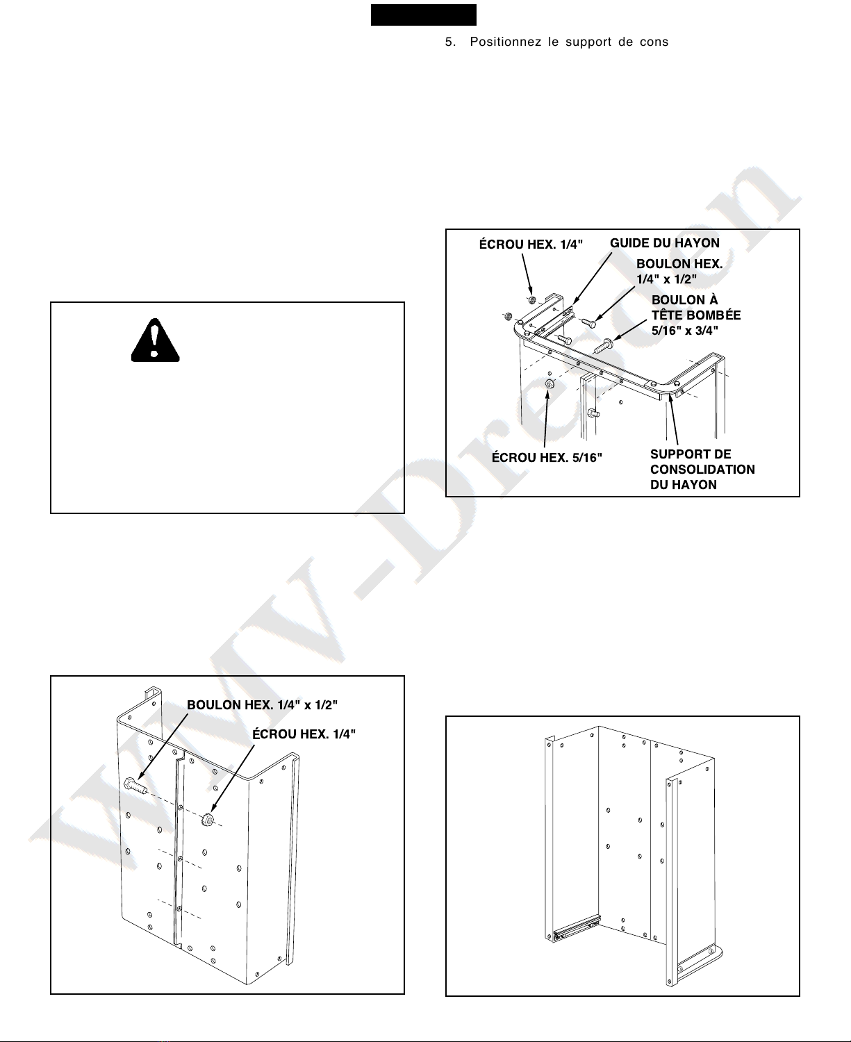
5. Positionnez le s pport de consolidation d hayon à
l'extérie r de la remorq e comme montré dans la fig re
3. Assemblez-le avec la partie basse de la carrosserie
en tilisant q atre bo lons à tête bombée de 5/16” x
3/4” et des écro s hex. de 5/16”. Ne serrez pas pour
l'instant. Voir fig re 3.
6. Positionnez les g ides de hayon à l'intérie r des
éléments de carrosserie avec les glissières de g ide
vers l'avant comme montré dans la fig re 3. Assemblez
en tilisant q atre bo lons hex. 1/4” x 1/2” et des
écro s hexagona x de 1/4”. Ne serrez pas pour
l'instant. Voir fig re 3.
FIGURE 3
FIGURE 4
7. A ce stade, ayant les éléments de moitié de carrosserie
liés l' n à l'a tre, serrez les q atre bo lons à tête
bombée assemblés lors de l'étape 5 et ens ite, les
q atre bo lons hex. assemblés lors de l'étape 6. Laissez
à part po r le moment les bo lons ayant été assemblés
lors de l'étape 4.
8. Renversez avec préca tion la position de la charrette
de telle sorte q 'elle repose s r la partie arrière, s r le
s pport de consolidation de hayon q i vient j ste d'être
assemblé, comme montré dans la fig re 4. Procédez
ens ite a x étapes de montage q i s ivent.
FRANÇAIS
BOULON HEX.
1/4" x 1/2"
BOULON Ë
TæTE BOMBE
5/16" x 3/4"
CROU HEX. 5/16"
CROU HEX. 1/4"
SUPPORT DE
CONSOLIDATION
DU HAYON
GUIDE DU HAYON
This manual suits for next models
2
Table of contents
Languages:
Popular Outdoor Cart manuals by other brands


Crest Audio
Crest Audio Versarray VR Specifications and Instructions

Premier Mounts
Premier Mounts UPD Series Specifications

YTL
YTL YTL-010-757 Instructions & assembly

Simply Tidy
Simply Tidy ORDONNEZ 10591998 manual

Ziegler & Brown
Ziegler & Brown ZG3GCARTC Assembly instructions

Great Little Trading
Great Little Trading Time for Tea Trolley quick start guide


