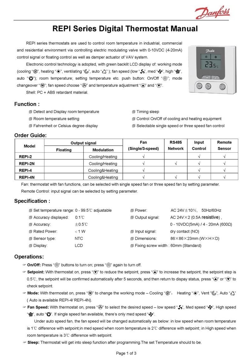
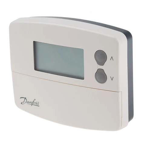
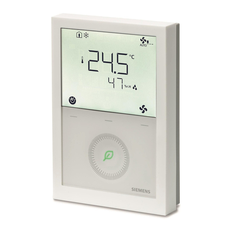
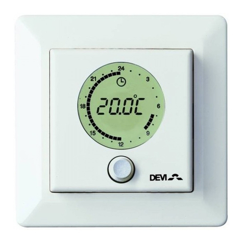
Speedheat SH-SmartStat User manual

!IMPORTANT!
READ THE INSTRUCTIONS
BEFORE INSTALLATION.
!
This thermostat has been designed to provide you with years of trouble free
service. Proper understanding of any product is the key to using it
successfully. By spending only a few minutes reading through this manual,
you will become acquainted with the many features built into this
thermostat. Following the procedures listed within this manual will minimise
the risk of damaging the thermostat or any of the equipment it controls.
Please take special notice of all as these contain important
information and safety tips.
NOTES
1. CONTENTS
SPECIFICATIONS .................................. 2
POSITIONING THE THERMOSTAT........ 3
OPENING THE THERMOSTAT.............. 4
TOOLS REQUIRED................................ 5
PREPARATION & WALL MOUNT........... 6
WIRING DIAGRAMS............................... 7
FEATURES.............................................. 8
FLOOR TEMPERATURE SENSOR....... 9
SELECTION OF OPERATION MODE... 10
2. SPECIFICATIONS
PHYSICAL DIMENSIONS:
L 125mm X W 90mm X D 34mm
MAX. SWITCHING CAPACITY:
230Vac / 8 Amp (1.8 kW) Resistive.
POWER SUPPLY: 230Vac 50 Hz
TEMPERATURE DISPLAY: Celsius
TIME DISPLAY: 24 hour
TEMPERATURE DIFFERENTIAL
0.5-1.0°C (Fact. = 0.5°C)
SET-POINT ADJUSTMENT: 1.0
TEMPERATURE DISPLAY RANGE:
-10 to 45°C
TEMPERATURE CONTROL RANGE:
5 to 32°C
PROGRAMMING PERIODS:
Monday - Friday : 6 periods / Day
Saturday - Sunday : 4 periods / Day
OPTIONAL ACCESSORY:
Floor sensor cable for max. floor
temperature limitation.
°C
1. The thermostat should be fitted on an inside wall of the room where the
heating is installed, approx. 1.5 m (5 ft.) above the floor.
2. Avoid areas which have unusual heating or cooling conditions, such as
direct sunlight, near a fireplace, stove, door, window or stairway.
3. Be aware of furnishings which may block airflow or alter the temperature
such as: sofas, chairs, bookcases, track lighting, lamps, stereo equipment,
television sets etc.
4. Note that hot water pipes in the wall, a stove, refrigerator or fireplace on
the other side of the wall may also affect the operation and accuracy of
your thermostat.
5. Positioning the thermostat in a damp area will cause corrosion and shorten
the life of the thermostat.
6. Do not install the unit where air circulation is poor (e.g. in a corner, alcove,
or behind a door).
7. All construction work and painting must be completed before installation.
N.B. This thermostat does not require levelling.
!
3. THERMOSTAT POSITIONING
Proper positioning of the thermostat is very important to
ensure accurate room temperature measurement.
Observe the following general rules for best results.
!
To avoid electrical shock and to prevent damage
to the floor heating and thermostat, disconnect
the power supply before proceeding with the
installation.
To refit the thermostat body to the base plate, hook the body onto the
bottom of the base plate (see photograph). Press both parts together until
the unit snaps shut.
5. TOOLS REQUIRED:
#1 Philips Screw driver (small)
Drill with 4.5 mm (3/16”) bit (if using anchors)
Wire strippers or utility knife, masking tape & pen (for labelling wires).
Attach wires to terminal screws
using the appropriate wiring
diagram (see 7). When finished,
refit the terminal cover.
NB. If you are unfamiliar with
electrical wiring, contact an
electrician for assistance.
When mounting the thermostat on a
soft surface, like plasterboard, where
the screws might not hold securely,
you will need to make mounting holes.
Remove the terminal cover.
Using the base as a
guide, mark the screw
locations on the wall.
Drill a 5 mm (3/16”)
hole at each of the
screw locations, and
insert plastic anchors.
4
12356
Hold thermostat base against the wall,
with the electric wires coming through
wherever it is convenient for wiring.
Route the wires above the terminal
strip and attach the base to the wall
with the screws provided.
1
Connect the electric
wiring as shown
in the diagram on the
inside of the base
plate.
4. OPENING THE THERMOSTAT
Before you connect the wiring you must check your system's wiring
diagram or consult with a professional electrician.
7. WIRING DIAGRAMS
6. PREPARATION AND WALL MOUNT
SETTING THE CLOCK.................. 11
PROGRAMMING.......................... 12
SET SWITCHING DIFFERENTIAL.. 13
MANUAL OPERATION MODE........ 14
TEMPORARY OVERRIDE............. 15
COMFORT OVERRIDE................. 16
BATTERY LOW INDICATOR...........17
FUSE
220V - 240V
50-60 Hz
L
N
4 5 6
Thermostat
HEATER
Note that the maximum load should be limited to 8 Amps (1800
Watt @ 230 Vac). For bigger loads, use a slave contactor.
Blue or
Gn+Yw
Brown or
Bk+Rd
Live supply
Heater(s)
Be careful not to drop the body or to disturb any electronic parts.
Leave the flap closed and separate the body from the base plate.
!
While holding the thermostat
face in the palm of your hand,
press the release button with
your thumb.
Hold on firmly to the baseplate with your other hand by placing your fingers
on both sides of the thermostat. Whilst keeping the release button pressed,
swing the thermostat away from it’s base.
8A (2A)
4
12356
8A (2A)
PROGRAMMABLE THERMOSTAT
Model:
SH-SmartStat

PRESET
TEMPERATURE
indicator
Vacation hold & comfortable
hour indicator / current PROG
indicator
Set Mode indicator
Current PROG
INDICATOR
Current system mode
Current mode
indicator
Day of the week
Time display
FAN control option
Room temperature display
24H FORMAT
DAY
COMF.
HOLD
HEAT
COOL
TEMP SET
This particular thermostat is a programmable model. It has a built-in clock
and can change its temperature settings automatically throughout the day.
This has the advantage of ensuring that the temperature in your home is set
to optimum efficiency at all times.
For example, during the winter months you may wish to set your heating
system to warm up the room to 21°C. This is a comfortable temperature in
the house when you are at home. However, it would waste a lot of electricity
to maintain that temperature all day when you are out.
With a programmable thermostat you can set the temperature back, e.g. to
16 C while you are out, and to 18 C at night while you are asleep and still
maintain a comfortable temperature level during the times that you are
relaxing at home.
An efficient heating system should "kick in", or cycle, four to six times per
hour while maintaining one set temperature. However, if the temperature has
been set back to a lower level, the heating system will have to run longer to
recover to the comfort level.
° °
The question here is: how many degrees can you set the temperature back
to keep the heating from cycling when you don't need it, and still be able to
bring the temperature back up to your comfort level without the heating
system having to run excessively?
Many factors will affect this balance: How big is the difference between
outside and inside temperatures? How large is your house? How powerful is
your heating system? How well is your house / your floor insulated? How
long and at what times are you away from home? How many hours do you
sleep and at what times?
The pre-programmed times and temperatures within your thermostat can
be adjusted to suit your needs. Please read the section on the next few
pages for more information on how to achieve this.
2) Mode which sets individual programmes for each day of the week.
Once the power is connected the LCD SCREEN will show all symbols for 5
seconds. Thereafter, the LCD SCREEN will display "5:2d" (default). You
can now press the "NEXT" button to select "7d”.
Pressing the “NEXT” button toggles between "5:2d" and "7d".
"7d"
Pre-programmed Times & Temperatures
FACTORY PRESET TIME/TEMPERATURE PROGRAMME
MON, TUE, WED, THU, FRI
SATURDAY
SUNDAY
P1
P1
P1
P2
P2
P2
P3
P3
P3
P4
P4
P4
P5
P6
TIME
TIME
TIME
06:00
07:00
07:00
08:30
08:30
08:30
12:00
16:30
16:30
14:00
22:30
22:30
16:30
22:30
TEMPERATURE
TEMPERATURE
TEMPERATURE
21°C
21°C
21°C
16°C
21°C
21°C
21°C
21°C
21°C
16°C
18°C
16°C
21°C
18°C
After selecting the 5:2d or 7d mode, press the
key or wait for 10 seconds, the thermostat will
then set the day and time to SUNDAY (Day 7),
0:00 and display the room temperature.
9. FLOOR TEMPERATURE SENSOR (OPTIONAL).
10. MODE OF OPERATION SELECTION
The floor sensor should be installed exactly in between two runs of the
heating element and taped / glued down. The sensor is necessary to
prevent overheating of sensitive flooring (wood, vinyl). The maximum
temperature of the floor surface is determined by the floor covering
manufacturer (typically 27°C).
The floor sensor cable must be connected to terminals 1 and 2. The sensor
cable may be shortened. In case of the thin probe, the green and yellow
wires as well as red and black wires must be crimped together in the
ferrules (supplied with the thin probe) and connected resp. to the terminals
1 & 2. (See 7. WIRING DIAGRAMS).
When installation is complete, fit the thermostat to the base, then reset the
thermostat by pressing the "RESET" button. The thermostat will thereafter
automatically check if the floor sensor is installed and display the room
temperature.
If the floor sensor cable is not installed, the floor temperature detecting
function cannot be used. Whenever the floor sensor cable is installed, reset
the thermostat by pressing the "RESET” button.
In this mode, the thermostat will ignore the floor sensor. The temperature of
the room will determine whether the heating system is on or off.
In this mode, the thermostat will continuously compare the floor and room
temperatures to the preset temperature settings.
Important!
Two modes of operation may be selected:
1. Room temperature controller:
2. Room temperature controller with max. floor temperature limitation:
2
At the initial setting of this thermostat, one of two modes may be selected:
1) Mode which sets weekdays and weekends (Saturday & Sunday)."5:2d"
Cooling system
active indicator
Heating system
active indicator
8. FEATURES
HEAT-OFF switch
Saves programmes in
memory and returns to
normal display Sets the temperature
Adjusts time and day
of the week
Changes the
programme
Temperature &
vacation HOLD
Set Maximum
FLOOR Temperature
Manual MODE and
comfortable Hours SET
Reset button for
system reset
Easy to read digital
LCD display
HEAT
OFF
NEXT
RESET
COMF.
CLOCK
SET
PROG.
SET
HOLD
FLOOR
SET
Info: Display
programmes

1. Mode Selecting:
Press and hold the "NEXT" button for 5 seconds. The LCD
will display the current operation control mode: Room
Temperature mode or Floor Temperature limitation mode.
Then press or to select a different mode.
When you have selected your setting, press the
button to return to normal operation.
p q
Room temp mode
Floor temperature
limitation mode.
(This happens automatically if no button is pressed
for 10 seconds.)
3. If the "Floor temp. limitation mode" is disabled:
When the thermostat is operating under "Room
temperature mode ( )", pressing the FLOOR
SET button will cause the LCD to display the
current floor temperature. However, the maximum
floor temperature cannot be set.
FL:O
3
µ
µ
CLOCK
SET
µ
µ
To set the clock, press the button.
The day of the week will start flashing.
etc. Use and to choose the current
day of the week. Press “NEXT” to set the hour.
The display will flash the hour digits.
1=MON,
2=TUE p q
Use and to select the current hour. To
continue, press ”NEXT” to set the minutes. The
minutes in the display will start flashing.
p q
Use and to select the current minute.
“NEXT” will continue cycling through the options.
To return to normal operation press . The
display will stop flashing.
p q
µ
µ
11. SETTING THE CLOCK
Maximum floor temperature setting:
Set the thermostat to "Floor temperature limitation mode" (FL:A).
Press the “FLOOR SET” button. The LCD will display the actual floor
temperature in the centre of the display.
Press the or button to set the maximum floor temperature (Left top).
The “TEMP SET” at the upper left-hand corner of
The LCD will vary from 26°C (factory default) to
Your selected setting.
The diagram below shows temperature set at 36°C
p q
-
-
-
-
2.
TO CHANGE a programme memory, press then press
for the specific programme you wish to enter. The display should
change to the 1st Period (P1) with the SET TEMPERATURE
flashing.
PROG.
SET
PROG.
SET
7D
5:2D
µ
µ
7D
5:2D
µ
µ
Switching differential is the term given to the amount the thermostat will
allow the temperature to vary from the Set Temperature. This feature allows
you to decide how closely the thermostat will control the temperature in the
room. A smaller switching differential will switch the system on & off more
frequently.
Your thermostat is factory preset to allow the room temperature to rise
0.25°C above the Set Temperature, and then it will let it drop 0.25°C below
the Set Temperature (0.5 C differential). This differential can be changed
from 0.5 C to 1.0 C, in which case the thermostat will switch less
frequently.
Example: it's cold outside and the heating unit is running. It has raised the
room temperature to 21°C. Your thermostat has been set to 21°C and the
preset switching differential to 1.0 C. The heating unit will continue running
until the room temperature reaches 21.5°C before shutting off. The
temperature will then begin to drop until it reaches 20.5°C. At this point
the thermostat will switch the heating back on again.
°
° °
°
13. SET SWITCHING DIFFERENTIAL
Use the ”NEXT” button to select 0.5°C or
1.0°C differential
µ
12. PROGRAMMING
The setting of the differential does not affect the electricity consumption of
the heating system. The higher differential causes the thermostat to switch
on and off less frequently, which increases the lifetime of the switch
contacts.
In most cases the factory setting of 0.5°C is suitable.
When either of these temperatures are reached the
thermostat will switch the heating system off.
Note!
Do not set the thermostat to “Floor temperature limitation mode” if no floor
sensor cable is installed. Pressing the FLOOR SET button will not display the
floor temperature!
Use the button to set the time forward. Use the button to set
the time back. Once you have selected the correct Start Time press
“NEXT” again to move to the set temperature of the 2nd period (P2).
p q
Use the and buttons to adjust the temperature. Once the Set
Temperature is correct press the “NEXT” button again to move to
the Start Time set for this period.
p q
µ
µ
PROG.
SET
Use q pand to make adjustments where necessary.
Continue cycling through each period. Set Temperature and
then Start Time by pressing “NEXT”. Once selection is
complete press the to the NEXT DAY PROGRAMME
BLOCK, or press to return to normal operation.
To change the differential, press and
hold . Then press qbutton for more
than 3 seconds. The display should
change and show the current differential
setting.
Press to return to normal operation.
(This happens automatically if no button
is pressed for 10 seconds).
Ensure that the OFF/HEAT switch is in the HEAT position,
otherwise the following operations will not work!

µ
µ
14. MANUAL MODE OF OPERATION.
By simply pressing the button you can
place your new thermostat into a Manual
operating mode, where temperature is
controlled at the selected setting.The Hold
indicator will show on the display confirming
that you have entered the Hold mode.
The and buttons are used to adjust the
temperature. If no button is pressed for 10
seconds the thermostat will go into
and display the current temperature. At any time
you can return to the Programme controlled mode
by pressing or .
If this Manual mode is preferable for most of the time, you may opt for a
conventional (non-programmable) thermostat.
If you have experimented with the different programmed times and
temperatures and yet have not achieved optimal savings or comfort, this may
be due to the poor insulation of your home, or a heating system that may
have too slow a recovery rate to allow for setting the temperature back or
forward.
Your lifestyle or job may be such that you spend a lot of time in your home.
Varying the settings of your thermostat may therefore be impractical as this
will not maintain the level of comfort achieved by a constant temperature. In
this case, a small set-back at night is optimal.
HOLD
HOLD MODE
HOLD
p q
4
MANUAL MODE / VACATION HOLD
You can use MANUAL MODE / VACATION HOLD to set a fixed temperature
whilst you are not at home for a number of consecutive days. The energy
consumption of your heating system can be drastically reduced by using this
function.
µ
µ
2. Press” NEXT” to set the number of vacation days.
3. Use the button to increase or the button to decrease the number of
vacation days; if no key is pressed for 10 seconds the thermostat will run the
VACATION HOLD MODE and display the current temperature.
p q
µ
µ
4. At any time you can return to the programme controlled mode by pressing
again or .HOLD
A Temporary Override has been provided to allow you
to temporarily change the temperature without altering
the thermostat's programme. The thermostat will use
the new temperature setting during the duration of this
programme period. At the start of the next programme
period, the override will be cancelled and the
thermostat will return to programme mode.
15. TEMPORARY OVERRIDE
To activate the override all you simply need to do is
adjust the temperature using the and buttons.
p q
The Override indicator will display in the top right-
hand corner. After approx. 10 seconds the
thermostat will start running in Temporary Override
mode. The Rotary Time Display will show the
selected time under Temporary Override mode.
(The present time block will start flashing.)
If the time remaining until the next programme period is not practical for your
needs (e.g. you have visitors and the house is getting too warm), you can
lower the temperature by using the override option. The display shows that
the override will only last for an hour and two minutes. If your visitors are
staying longer than an hour or two, using Comfort Override would be
preferable. (see the next section). As indicated above, you may return to the
programme mode at any time by pressing .
Comfort Override allows you to change the
temperature for a specific number of hours (from
one to nine) without altering the thermostat's
programme. The thermostat will use the new
temperature setting for the specified amount of
time, then the thermostat will return to the
temperatures stored within the programme.
To activate Comfort Override press COMF. Simply
adjust the set temperature (Setpoint) using the
and buttons.
Press “NEXT” . The COMF indicator will show as it
does for comfort hours.
p
q
µ
µ
16. COMFORT OVERRIDE
You now have approx. 10 seconds to enter the
desired length of time by pressing once for each
hour the new Temp Setting should be in effect. The
display COMF indicator will show Comfort Hours
and the Rotary Time Display shows the time period
that it will be in effect.
After about 10 seconds the override mode will be
activated for the number of hours you have set.
You may cancel override mode and return to
normal programme mode at any time by pressing
COMF again or .
p
µ
As the batteries of your thermostat begin to weaken, the LCD display will
become faint. The thermostat will however continue to function normally.
The time, programs and all settings are saved by the batteries. When the
batteries become very weak, the thermostat will display "Lo" in place of the
room temperature. When this happens, replace the batteries as soon as
possible.
Switch the heater(s) off and remove the body from the
base plate to gain access to the battery holder. (For help
see page 1 under 4: Opening the thermostat).
Important: From the moment you remove the batteries,
you have only approximately 45 seconds to install new
batteries without losing the settings!.
17. BATTERY LOW INDICATOR
FOR MORE INFORMATION VISIT OUR WEB SITE ON :
www.speedheat.co.za
Other Speedheat Thermostat manuals
