Speedsignal Elw-Tec B-360DB03 User manual

B-360DB03_R1 20.02.2023 Seite 1 von 20
10R – 058209 für 3540008
EINBAUANLEITUNG
INSTALLATION GUIDE
B-360DB03 Mercedes 10,25”
LARDIS:ONE DS
1920
720
Nur für Fahrzeuge mit SPV-Eingang
Only for vehicles with SPV input

B-360DB03_R1 20.02.2023 Seite 2 von 20
Fahrzeuge Vehicles
Mercedes
Infotainmentsystem
MBUX NTG 6 Der DisplaySwitch funktioniert nur für
Fahrzeuge, die das genannte
Infotainmentsystem haben.
The DisplaySwitch works only for vehicles
that have the mentioned infotainment
system.
Display
Auflösung Resolution
1920*720
Diagonale Diagonal
10,25“ = 26 cm
Achtung Attention
Der DisplaySwitch funktioniert nur
für Fahrzeuge, die den
markierten SPV-Eingang an der
Headunit besitzen!
The DisplaySwitch only works for vehi-
cles that have the marked SPV input on
the headunit!
A W177 (2018-)
B W247 (12/2018-)
CLA Baureihe 118 (2019-)
GLA H247 (2020-)
GLB X247 (2019-)
GLE V167 (2018-)
Sprinter III W907, W910 (2018-)

B-360DB03_R1 20.02.2023 Seite 3 von 20
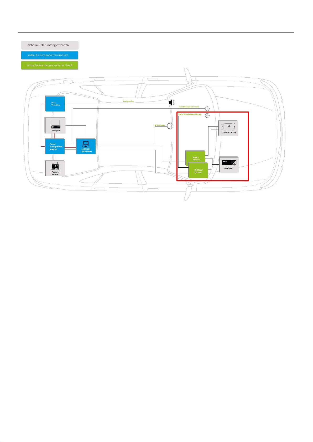
Lieferumfang Scope of delivery
DisplaySwitch Set Mercedes 10,25“
DisplaySwitch Set Mercedes 10,25“
Powermanagement Set Mercedes
Powermanagement Set Mercedes
Mono-Verstärker Set
Mono Amplifier Set
Bordrechner Set Mercedes 10,25”
On-board computer set Mercedes 10,25”
3540008
3676314
C-3540008
3630098
356ASRGN1911
369DB01-02
Ohne Artikelnummer
Without article number
C-3670079
3630108
C-3674727-USB27
356ASRGN1909
3670033
C-3670033
3910030-02
3911137
Ohne Artikelnummer
Without article number
3630104
3630105
3630107
B-360DB03_R1 20.02.2023 Seite 4 von 20
Einbau Part 1: DisplaySwitch Installation part 1: DisplaySwitch
1. Ausbau Headunit (Fundort fahrzeugabhängig)
2. Plug&Play Anschluss der Kabelsätze
3. Anschluss der Interfaces an Kabelsatz
4. Installation des Tasters
5. 5m USB-Verlängerungskabel und 5m DVI auf HDMI Kabel in den Kofferraum verlegen
1. removal of headunit (location depends on vehicle)
2. plug&play connection of the cable sets
3. connection of the interfaces to the cable set
4. installation of the button
5. Install 5m USB extension cable and 5m DVI to HDMI cable in the trunk
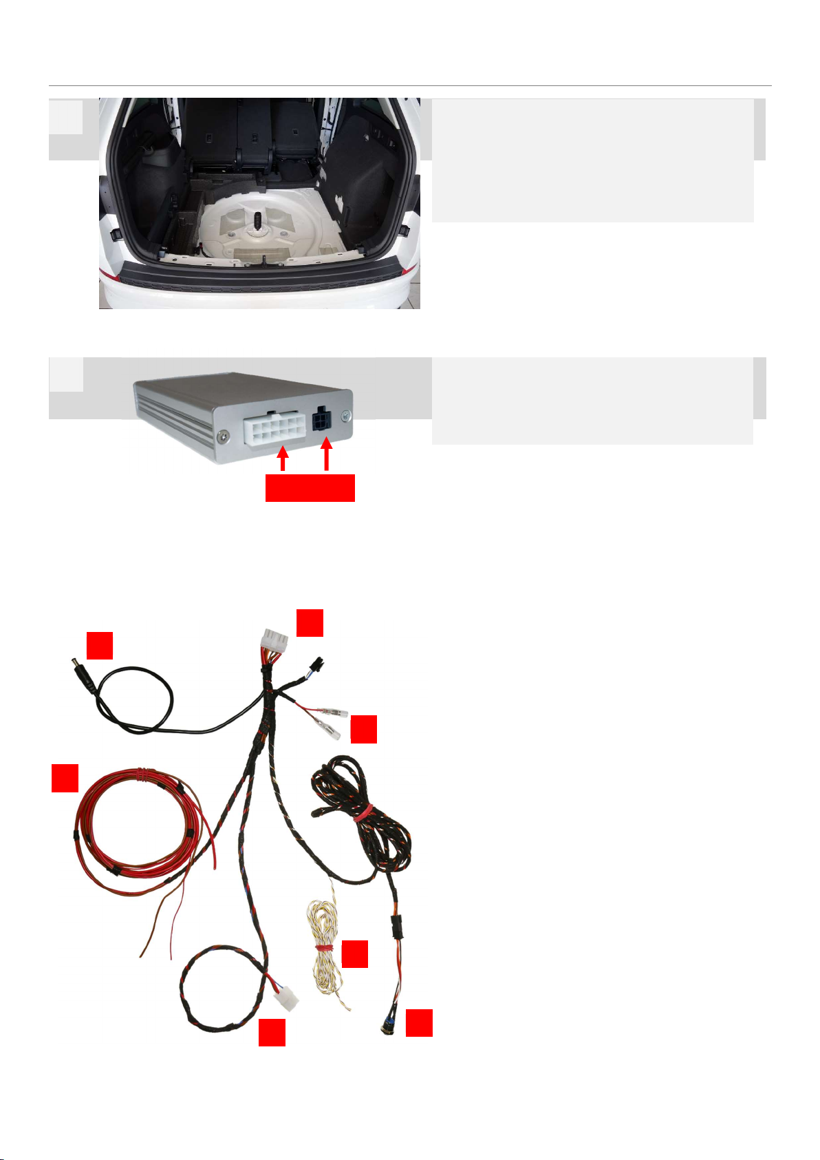
B-360DB03_R1 20.02.2023 Seite 5 von 20
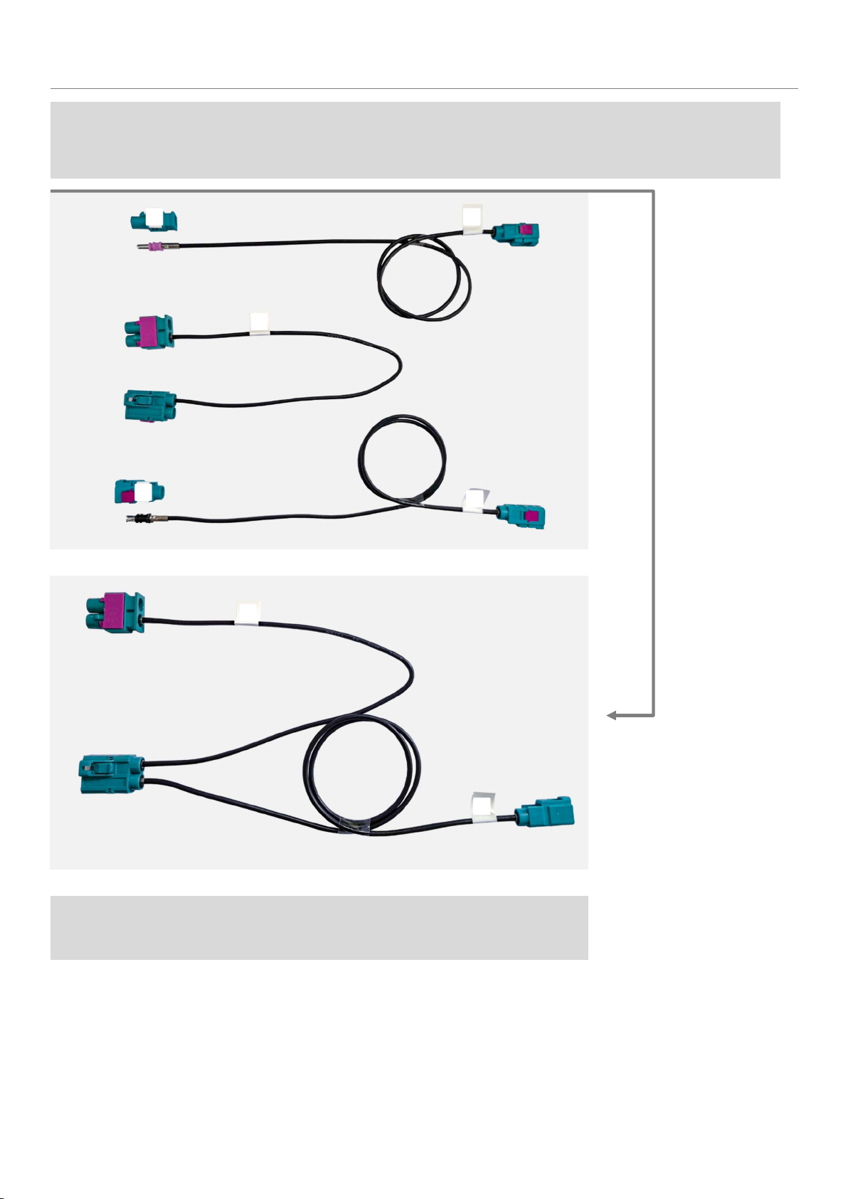
Im Lieferumfang ist ein Fakra-Kabelset enthalten, welches vor Beginn des Einbaus entsprechend zusammengesteckt werden muss.
Im Folgenden wird dies gezeigt.
The scope of delivery includes a Fakra cable set, which must be plugged together accordingly before starting the installation. This is shown below.
Fakra-Kabel 3630098 Fakra cable 3630098
D
B
C
A
E
C
A
Die übrig gebliebenen Kabel bzw. Stecker sind für den weiteren Einbau irrelevant.
The remaining cables or connectors are irrelevant for further installation.

B-360DB03_R1 20.02.2023 Seite 6 von 20
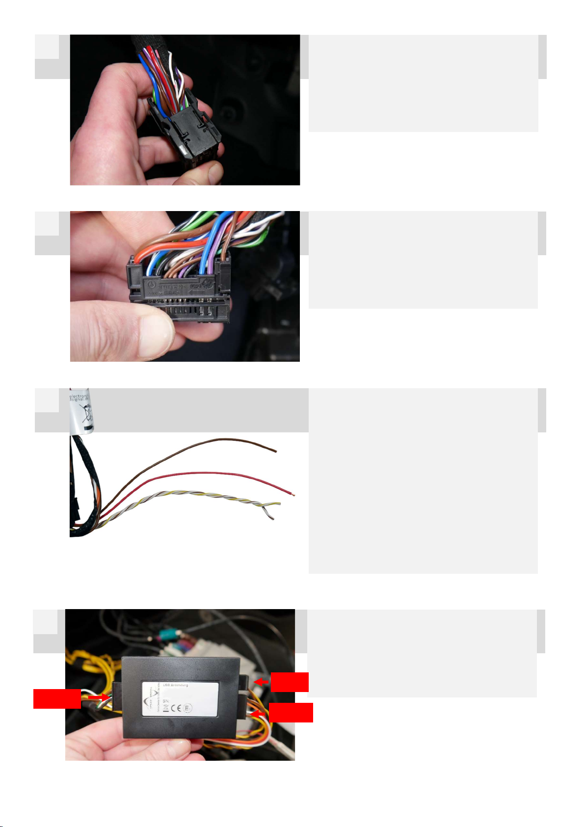
Nun muss sowohl der grüne Stecker des SPV-Eingangs (1),
als auch der markierte, schwarze Stecker (2) abgesteckt
werden.
Now both the green plug of the SPV input (1) and the marked
black plug (2) must be disconnected.
Einbau DisplaySwitch Installation DisplaySwitch
Die Headunit befindet sich an markierter Stelle im
Fahrerfußraum.
The headunit is located at the marked position in the driver's
footwell.
1
2
1 2
Nun muss der Kabelsatz angesteckt werden. Blau markier-
ter Stecker (1) am Steckplatz des SPV-Eingangs anstecken.
Grün markierter Stecker (3) am fahrzeugseitigen, zuvor ab-
gesteckten SPV-Stecker anstecken.
Now the cable set must be plugged in. Plug the blue-marked con-
nector (1) into the SPV input slot. Plug the plug (3) marked green
into the SPV plug on the vehicle side that was previously un-
plugged.
Nun den orange markierten Stecker (4) am Display-Inter-
face 3676314 anstecken.
Den 4-polige Microfit-Stecker vom Kabelsatz C-3540008
ebenfalls an das Interface anstecken.
Now connect the orange marked plug (4) to the display interface
3676314.
Connect the 4-pin microfit connector of the cable set C-3540008
to the interface as well.
3
4
1
3
4
4-pin Microfit
B-360DB03_R1 20.02.2023 Seite 7 von 20
12-poligen, 10-poligen und 6-poligen Microfit
Stecker vom Hauptkabelsatz C-3540008 an das Interface
3540008 anstecken.
Connect the 12-pin, 10-pin and 6-pin Microfit
plug from the main cable set C-3540008 to the
interface 3540008.
6
-
pin
10
-
pin
12
-
pin
6
CAN High: Pin 7, lila-weiß violet-white
CAN Low: Pin 20, lila violet
+12V: Pin 14, rot-grau red-grey
Masse Ground: Pin 1, braun brown
Hier zu sehen: schwarzer Stecker von Headunit abgesteckt
(siehe Schritt 2). An diesem Stecker können CAN-Bus,
Masse und +12V abgegriffen werden. Dafür muss die
Gehäusekappe entfernt werden.
Here you can see: black plug disconnected from headunit (see
step 2). CAN bus, ground and +12V can be tapped at this connector.
The housing cap must be removed for this.
5
6
Abgebildete Leitungen des Kabelsatzes C-3540008 tech-
nisch einwandfrei mit zuvor beschriebenen Fahrzeugleitun-
gen verbinden.
10-poligen und 12-poligen Microfit-Stecker vom Kabel
C-3540008 an das Interface 3540008 anschließen.
Connect the illustrated cables of cable set C-3540008 with the
vehicle cables described above in a technically correct manner.
10-pin and 12-pin Microfit connector from cable
C-3540008 to the interface 3540008.
CAN High: weiß gelb white-yellow
CAN Low: weiß-braun white-brown
+12V: rot red
Masse: braun brown
7
B-360DB03_R1 20.02.2023 Seite 8 von 20
6
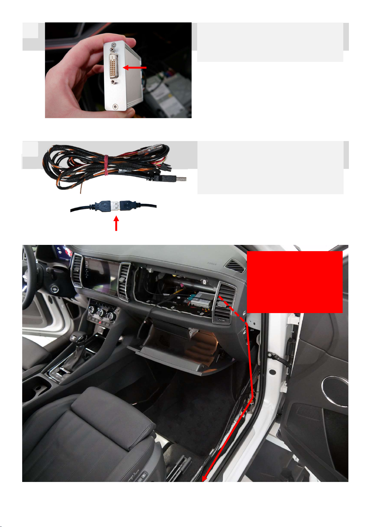
Am Interface 3676314 das 5m HDMI auf DVI Kabel anschlie-
ßen und in den Kofferraum verlegen.
Connect the 5m HDMI to DVI cable to interface 3676314 and install
it in the trunk.
7
Am Kabelsatz das 5m USB-Verlängerungskabel
anschließen und in den Kofferraum verlegen.
Die Verbindung sollte mit Klebeband fixiert werden.
Connect the 5m USB extension cable to the cable set and install it
in the trunk.
The connection should be fixed with tape.
8
Beide 5m Kabel
hinter den
Verkleidungen in den Koffer-
raum verlegen.
Install both 5 m cables behind
the trims in the trunk.

B-360DB03_R1 20.02.2023 Seite 9 von 20
Einbau Part 2: PMA Installation part 2: PMA
1. Anschluss Stromversorgung (+ Sicherungen)
2. Anschluss CAN-Bus (fahrzeugabhängig)
3. Taster (Funk-Hauptschalter) in der Front verbauen
1. power supply connection (+ fuses)
2. connection CAN bus (depending on vehicle)
3. install the push-button (radio main switch) in the front
B-360DB03_R1 20.02.2023 Seite 10 von 20
Einbau PMA Installation PMA
Der Powermanagementadapter wird, wie alle folgenden
Komponenten; im Kofferraum verbaut.
Üblicherweise wird hierfür die Reserverad-Mulde genutzt.
The powermanagementadapter, like all the following components,
is installed in the trunk.
The spare wheel compartment is usually used for this purpose.
1
Hauptkabelsatz C-3670079 an Powermanagementadapter
369DB01-02 anschließen.
Connect main cable harness C-3670079 to
powermanagementadapter 369DB01-02.
2
C
-
3
670079
1. Anschluss an PMA
2. Stromversorgung an Mono Verstärker
3. Anschluss Taster (hinter Verkleidung ins Cockpit verlegen)
4. Anschluss CAN-Bus (fahrzeugspezifisch)
5. Stromversorgung Funkgerät
6. Anschluss Stromversorgung an Fahrzeugbatterie
7. Stromversorgung Bordcomputer
1. connection to PMA
2. power supply to mono amplifier
3. connection to push-button (install behind trim in cockpit)
4. CAN-bus connection (vehicle-specific)
5. radio power supply
6. power supply connection to vehicle battery
7. power supply to on-board computer
7
6
5
4
3
2
1

B-360DB03_R1 20.02.2023 Seite 11 von 20
Der Anschluss des CAN-Bus ermöglicht es dem Bordrechner beim Anlassen der Zündung oder wahlweise beim Aufsperren des Fahr-
zeugs hochzufahren. Des Weiteren wird hierdurch auch die Tag- / Nacht-Umschaltung ermöglicht
The connection of the CAN bus enables the on-board computer to start up when the ignition is started or optionally when the vehicle is unlocked.
Furthermore, this also enables the day/night switchover.
3. Anschluss CAN-Bus CAN bus connection
Die abgebildeten CAN-Leitungen müssen mit dem CAN-Bus des Fahrzeugs (verdrilltes Adern-Paar)
verbunden werden. Wichtig ist, dass die abgebildeten CAN-Leitungen relativ nah am PMA ange-
schlossen werden. Überschüssiges Kabel kürzen!
- CAN High: weiß-gelb
- CAN Low: weiß-braun
Es empfiehlt sich den CAN-Bus im Kofferraum abzugreifen, wichtig ist, dass der gewählte CAN-
Bus folgende Signale bereit stellt:
- Zündung (Klemme 15)
- Hell-Dunkel-Erkennung (Tag- / Nacht-Umschaltung)
The CAN wires shown must be connected to the vehicle's CAN bus (twisted pair of wires). It is important that
the CAN wires shown are connected relatively close to the PMA. Shorten excess cable!
- CAN High: white-yellow
- CAN Low: white-brown
It is recommended to tap the CAN bus in the trunk. It is important that the selected CAN bus provides the
following signals:
- Ignition (terminal 15)
- Light/dark detection (day/night changeover)
Gängige CAN-Bus Farben: Common CAN bus colours:
MQB Plattform: VW / SEAT / Skoda + T6.1
- CAN High: grün (oder orange-grün) green (or orange-green)
- CAN Low: orange-braun orange-brown
MQB evo Plattform: VW / SEAT / Skoda + T6.1
- CAN High: grün green
- CAN Low: orange-braun orange-brown
MLB evo Plattform:
- CAN High: lila violet
- CAN Low: orange-braun orange-brown
MEB Plattform:
- CAN High: grün green
- CAN Low: orange-braun orange-brown
Audi:
- CAN High: grün green
- CAN Low: orange-braun orange-brown
Volvo:
- CAN High: weiß-grün white-green
- CAN Low: grün-gelb green-yellow
Ford:
- CAN High: grün (oder blau-grün) green (or blue-green)
- CAN Low: weiß (oder weiß-grün) white (or white-green)
Mercedes
- CAN High: braun-rot brown-red
- CAN Low: braun brown

B-360DB03_R1 20.02.2023 Seite 12 von 20
6. Anschluss Stromversorgung Power supply connection
1. Anschluss an Fahrzeug-Batterie
2. Kleiner Sicherungskasten
3. Quetschverbinder für rote Leitungen
4. Sicherungen für Hauptstromversorgung
1. connection to vehicle battery
2. small fuse box
3. crimp connector for red wires
4. fuses for main power supply
1
2
3
4
rote Leitung mit größerem Querschnitt: 10A Sicherung
rote Leitung mit kleinerem Querschnitt: 3A Sicherung
Red wire with larger cross-section: 10A fuse
Red wire with smaller cross-section: 3A fuse
B-360DB03_R1 20.02.2023 Seite 13 von 20
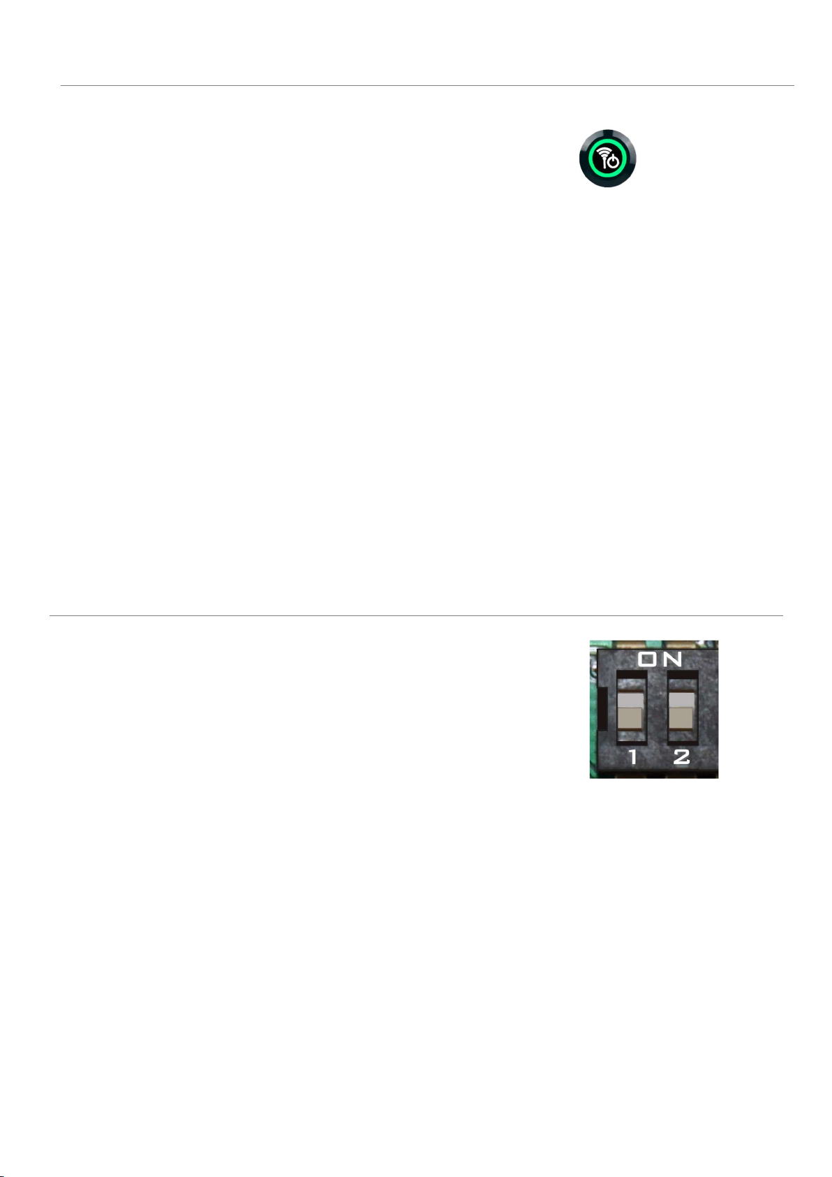
PMA Features PMA features
Spannungsüberwachung:
- Konstante Ausgabe von 12V
- LED des Funkhauptschalters blinkt bei drohender Unterspannung (Spannung < 11,8V)
- LED des Funkhauptschalters leuchtet bei Unterspannung (Spannung < 10,8V)
Voltage monitoring:
- Constant output of 12V
- LED of the radio main switch flashes in case of impending undervoltage (voltage < 11.8V)
- LED of the radio main switch lights up in case of undervoltage (voltage < 10.8V)
Geregeltes Hoch- und Runterfahren:
- Der Powermanagementadapter ermöglicht ein geregeltes Hoch- und Runterfahren des angeschlossenen PC`s und Funkgeräts
- Ausgelöst wird dies entweder durch Betätigung des Funkhauptschalters, oder durch den CAN-Bus (Zündplus)
- Wie das geregelte Hoch- und Runterfahren erfolgt, ist durch die Dip-Schalter frei einstellbar
Controlled start-up and shutdown:
- The power management adapter enables a controlled start-up and shut-down of the connected PC and radio unit.
- This is triggered either by actuating the radio main switch or by the CAN bus (ignition plus).
- The way in which the controlled start-up and shut-down takes place can be freely adjusted by means of the dip switches.
DIP-Schalter DIP switches
Dip-Konfiguration:
Dip 1: ON Funkhauptschalter = Taster
Dip 1: OFF Funkhauptschalter = Schalter
Dip 2: ON An- und Ausschalten des Funkgeräts via Funkhauptschalter
Dip 2: OFF An- und Ausschalten des Funkgeräts via CAN gesteuert
(wenn PC hochfährt, fährt Funkgerät hoch)
Dip configuration:
Dip 1: ON Radio main switch = push button
Dip 1: OFF Radio main switch = switch
Dip 2: ON Switching the radio on and off via radio main switch
Dip 2: OFF Switching the radio on and off controlled via CAN
(when PC starts up, radio starts up)
B-360DB03_R1 20.02.2023 Seite 14 von 20
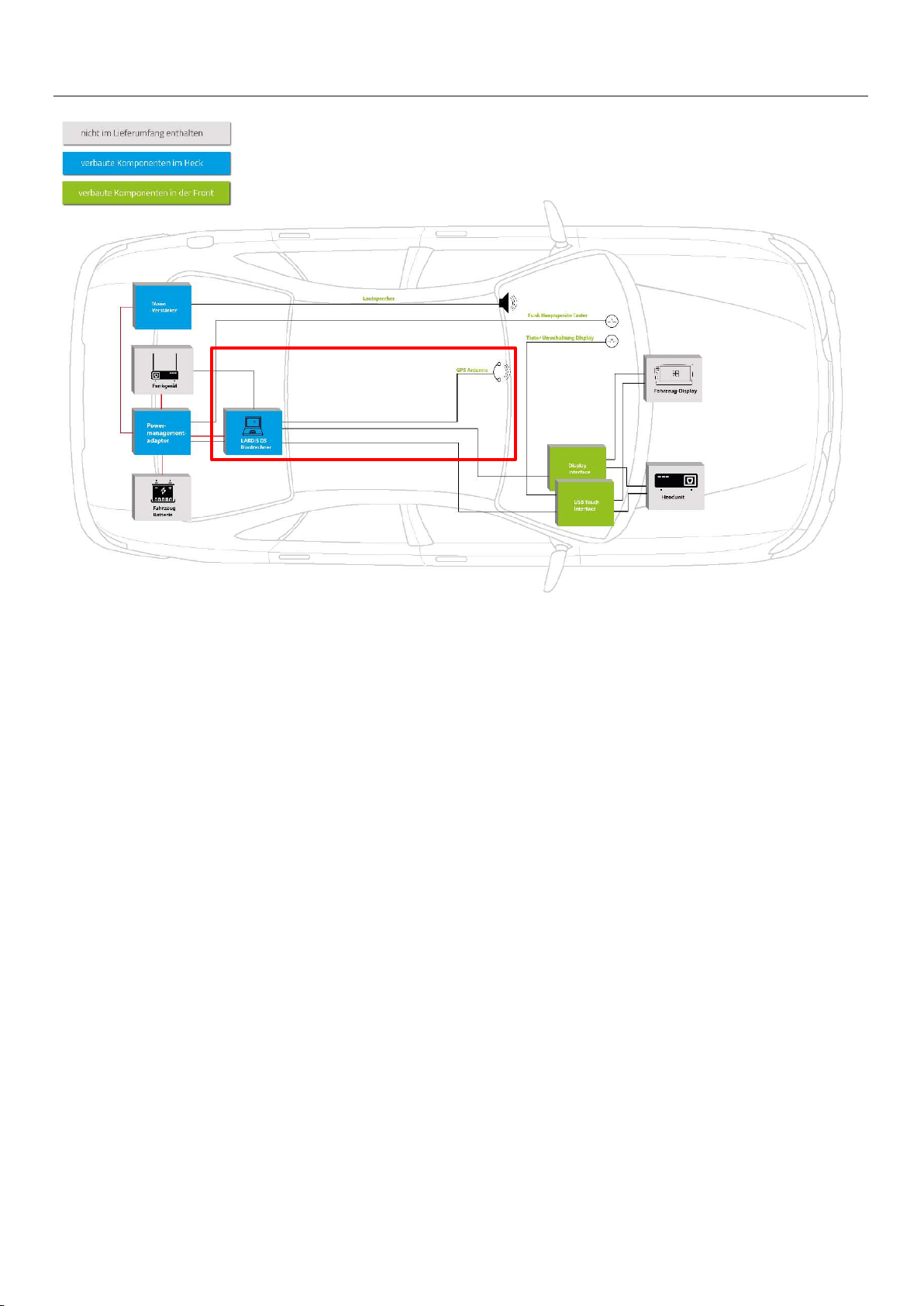
Einbau Part 3: Bordrechner Installation part 3: On-board computer
1. Bordrechner im Kofferraum verbauen
2. GPS-Antenne in der Front verbauen
3. Anschluss der aufgeführten Kabel an Bordrechner
1. install the on-board computer in the trunk
2. install the GPS antenna in the front
4. connect the listed cables to the on-board computer

B-360DB03_R1 20.02.2023 Seite 15 von 20
Einbau Bordrechner Installation on-board computer
Der Bordrechner wird ebenfalls im Kofferraum verbaut.
Die beigelegte GPS-Antenne wird im Cockpit angebracht.
The on-board computer is also installed in the trunk.
The enclosed GPS antenna is mounted in the cockpit.
1
Anschluss HDMI-Kabel
Verbindung zum USB-Touch-Interface
Connection HDMI cable
Connection to USB touch interface
Anschluss USB-Kabel Verbindung zum Funkgerät
Connection USB cable Connection to the radio
Anschluss USB-Kabel Verbindung zum Powermanagementadapter
Connection USB cable Connection to the powermanagementadapter
Anschluss Strom Verbindung zum Powermanagementadapter
Power connection Connection to the powermanagementadapter
Anschluss USB-Kabel Verbindung zum Video-Interface
Connection USB cable Connection to the video interface
Anschluss GPS Antenne
GPS antenna connection Anschluss Mono Verstärker
Connection mono amplifier
Kabelbinder zur Befestigung Zugentlastung
Cable ties for fastening Strain relief
Weißer Schalter rechts (bootet mit LARDIS Software)
Weißer Schalter links (bootet mit Odroid Software)
White switch right (boots with LARDIS software)
White switch left (boots with Odroid software)

B-360DB03_R1 20.02.2023 Seite 16 von 20
Einbau Part 4: Mono Verstärker Installation part 4: Mono amplifier
1. Kabelsatz mit Bordcomputer und Hauptkabelsatz C-3670079 verbinden
2. Lautsprecher anschließen (Plug&Play) und in der Front installieren
3. Interface und restlichen Kabelsatz im Kofferraum verbauen
1. connect cable harness with on-board computer and main cable harness C-3670079
2. connect the speaker (plug & play) and install it in the front
3. install the interface and the rest of the cable harness in the trunk

B-360DB03_R1 20.02.2023 Seite 17 von 20
Einbau Mono Verstärker Installation mono amplifier
Interface und Kabelsatz des Mono Verstärkers werden im
Kofferraum verbaut. Der Lautsprecher wird im Cockpit
angebracht.
Der Lautsprecher gibt die Signaltöne des PC’s aus.
Interface and cable set of the mono amplifier are installed in the
trunk. The loudspeaker is mounted in the cockpit.
The loudspeaker emits the signal tones of the PC.
1
Lautsprecher (Verbau in der Front) zur Ausgabe der PC-Systemtöne
Speaker (installed in the front) for the output of the PC system sounds
Klinkenstecker zum Anschluss an LARDIS DS Bordrechner
Jack plug for connection to LARDIS DS on-board computer
Versorgungsleitungen (Anschluss an Powermanagementadapter)
Supply wires (connection to power management adapter)
Verstärker Interface
Amplifier interface
Einstellungs-Rädchen:
Volume: (Grundstellung des Poti: Mitte)
Sensitivity: (Grundstellung des Poti: Mitte)
Wenn kein Ton: Volume auf voll, Tonausgabe und Sensitivity so lange
nach rechts drehen bis Ton kommt
Adjustment wheel:
Volume: (basic position of the potentiometer: centre)
Sensitivity: (basic position of the potentiometer: centre)
If no sound: set volume to full, turn sound output and sensitivity to the right
until sound is heard.

B-360DB03_R1 20.02.2023 Seite 18 von 20
Umschalten von originaler Quelle
zur PC-Ansicht
Switch from original source to PC view
Umschalten Switching
- Taster
- Num-Lock („Automatische-Umschaltung“)
- In der Mercedes-Oberfläche (Sonderfahrzeug)
- Ansteuerung durch MPM/PSM (wenn Sonderfahrzeugsteu-
ergerät verbaut ist)
- Button
- Num-Lock ("Automatic switchover")
- In the Mercedes interface (special vehicle)
- Control by MPM/PSM (if special vehicle control unit is installed)
Bullet-Stecker vom Kabel C-3540008 Bullet connector from cable C-3540008
GELB: +12V Dauerplus, max. 1A
ROT: Schaltsignal für rauf- und runterfahren eines angeschlos-
senen PC-Systems. Ausgabe von +12V, wenn Display aktiv
(Nicht nur Klemme 15!), max. 0,2A
BRAUN: Masse
YELLOW: Output, +12V continuous positive, max. 1A
RED: Output, signal for boot up and boot down of a connected PC sys-
tem.
Output of +12V, if display is active (Not only terminal 15!), max.
0,2A
BROWN: Output, ground
Besonderheiten Special features
Unsere DisplaySwitch ermöglicht das
Überblenden der PC-Anzeige mit fahrzeugeigenen
Informationen wie:
Our DisplaySwitch allows you to crossfade the
PC display with in-vehicle information such as:
- Klimaanzeige Climate display
- PDC
- Rückfahrkamera Rear view camera
- Augmented Reality

B-360DB03_R1 20.02.2023 Seite 19 von 20
Vorgang codieren:
- Zündung AN
- Tastendruck > 30sec
> bis Display „Diagnose“ anzeigt
- codiert 1920x720
Coding procedure:
- Ignition ON
- Press key > 30sec
> until display shows "Diagnostics
- encoded 1920x720
Codieren Coding
Originalzustand
Original condition
1
2
Automatischer Neustart des Systems. Sonderfahrzeug-But-
ton nun in Favoriten verfügbar.
Automatic restart of the system. Special vehicle button now
available in favorites.
3
Zum Deaktivieren der Sonderfahrzeugfunktion:
- Zündung AN
- Tastendruck > 30sec
-> bis Display „Diagnose“ anzeigt
- System startet automatisch neu
- Button Sonderfahrzeug ist verschwunden
To deactivate the special vehicle function:
- Ignition ON
- Press key > 30sec
-> until display shows "Diagnostics”
- System restarts automatically
- Special vehicle button has disappeared

B-360DB03_R1 20.02.2023 Seite 20 von 20
Die speedsignal GmbH gewährleistet innerhalb der gesetzlichen Frist von 2 Jahren ab Datum des Erstkaufes, dass dieses Produkt frei von Materialfehlern und Verarbeitungsfehlern ist, sofern dieses
Produkt unseren Vorgaben entsprechend verbaut wurde.
Sollten Reparaturen durch Verarbeitungsfehler oder Fehlfunktionen des Produktes innerhalb der Gewährleistungsfrist nötig sein, wird die speedsignal GmbH das Produkt reparieren oder durch ein
fehlerfreies Produkt ersetzen. Um die Gewährleistung beanspruchen zu können, benötigen Sie einen Kaufbeleg.
Der Garantieanspruch erlischt durch:
unbefugte Änderungen am Gerät oder Zubehör
selbst ausgeführte Reparaturen am Gerät
unsachgemäße Nutzung bzw. Betrieb
Gewalteinwirkung auf das Gerät (Herabfallen, mutwillige Zerstörung, Unfall, etc.)
Beachten Sie beim Einbau alle sicherheitsrelevanten und gesetzmäßigen Bestimmungen.
Bitte beachten Sie generell beim Einbau von elektronischen Baugruppen in Fahrzeugen die Einbaurichtlinien und Garantiebestimmungen des Fahrzeugherstellers.
Sie müssen auf jeden Fall den Auftraggeber (Fahrzeughalter) auf den Einbau eines Interfaces aufmerksam machen und über die Risiken aufklären.
Es empfiehlt sich, mit dem Fahrzeughersteller oder einer seiner Vertragswerkstätten Kontakt aufzunehmen, um Risiken auszuschließen.
speedsignal GmbH guarantees within the legal deadline of 2 years from the original date of purchase that this product is free from defects in material and workmanship as long as this product was
installed similar to our installation guide.
If repairs of processing errors or malfunctions of this product are necessary within the warranty period, speedsignal will repair the product or replace it with a flawless product. To be able to assert
the benefit of these provisions, you need the proof of purchase.
Warranty claim and operating license lapses:
unauthorised changes on the device or accessory
self-initiated repairs at the device
improper use or operation
violent impacts to the device (fall down, wanton destruction, accident, etc.)
For installation, please notice all safety and legal regulations.
When installing electronic assemblies into vehicles please note the installation guidelines and warranty conditions of the vehicle manufacturer.
In any case, you have to inform the principal (vehicle owner) about the installation of this interface and about all risks.
It is therefore recommended to get in contact with the vehicle manufacturer or with an authorized workshop to exclude any risks.
Der Einbau dieses Artikels darf nur von geschultem Fachpersonal vorgenommen werden und nur nach der in dieser Anleitung beschriebenen Vorgehensweise.
Die speedsignal GmbH übernimmt keinerlei Haftung für Personen- oder Sachschäden, die mit dem Missbrauch unserer Produkte im Zusammenhang stehen.
Vor der Montage bitte die Batterie abklemmen. Beim Einbau müssen alle zusätzlichen Versorgungsleitungen entsprechend ihres Querschnittes und ihrer Kabellänge abgesichert werden. (DIN VDE
0298-4)
The installation of this product should only be carried out by trained specialist personnel and in accordance with this manual.
speedsignal GmbH cannot accept any liability for injury to persons or damage to property from errors or mistakes in this operating manual.
Please disconnect the battery before you start with the installation. During montage all additional supply lines must be secured pursuant to their cross section and cable length. (DIN VDE 0298-4)
Garantiebestimmungen Warranty Conditions
Sicherheitshinweise Safety Instructions
Hersteller und Inverkehrbringer: speedsignal GmbH
Carl-von-Ossietzky-Straße 3 + 7
83043 Bad Aibling
Vertrieb und Support: elw-tec
Technischer Support: [email protected]
Telefon: +49 871 962 15 - 640
Table of contents
Other Speedsignal Car Video System manuals


Popular Car Video System manuals by other brands


AVA Enterprises
AVA Enterprises Universal Headrest user manual

Audiovox
Audiovox 1187001PL installation instructions

Blaupunkt
Blaupunkt San Pedro 950 operating instructions

Tview
Tview T91SV user manual

CarVision
CarVision UCONNECT installation instructions

Boss Audio Systems
Boss Audio Systems Vision BVT5.6 user manual